wipers PONTIAC FIERO 1988 Service Repair Manual
[x] Cancel search | Manufacturer: PONTIAC, Model Year: 1988, Model line: FIERO, Model: PONTIAC FIERO 1988Pages: 1825, PDF Size: 99.44 MB
Page 152 of 1825
STEERING WHEELS AND COLUMNS 385.1
SECTION 3B5
STEER NG WHEELS AND COLUMNS
NOTICE: All steering wheel and column fasteners are important attaching parts in that they could affect
the performance of vital parts and systems, and/or could result in major repair expense. They
must be replaced
with one of the same part number or with an equivalent part if
replacement becomes necessary. Do not use a
replacement part of lesser quality or substitute design. 'Torque values must be used as specified during reassembly
to assure proper retention of all parts. There is to be no welding as
it may result in extensive damage and weakening
of the metal.
For prevailing torque
nut(s) and bolts(s), refer to the "Reuse of Prevailing Torque Nut(<) and Bolt(s) " chart
in Section OA.
CONTENTS
..................... ................................................................... GENERAL DESCRIPTION .. 3B5-1 ............................................. ........................ MAINTENANCE AND ADJUSTMENTS .. 3B5-1 ON-CAR SERVICE ........................................................................................................ 3B5-2
Steering Column ............................................................................................................ 3B5-2 ......................................................................................................... Intermediateshaft 3B5-3
Park Lock Cable .................................................................... 3B54 ......................................................................................... Checking For Accident Damage 3B5-5 ............................................................................ Unit Repair Intermediate Shaft Assembly 3B5-6
..................................................................................... Standard Column @lanual Trans) 3B5-7 ......................................................... ....................... Standard Column (Auto Trans) .. 3B5-13 Tilt Column (Manual Trans) ............................................................................................. 3B5-19
Tilt Column (Auto Trans). ................................................................................................ 3B5-27
................ .................... TORQUE SPECIFICATIONS .. .. 3B5-35
SPECIAL TOOLS .......................................................................................................... 3B5-35
GENERAL DESCRIPTION
STEERING COLUMN
The function locking energy absorbing steering
column includes three important features in addition
to the steering function:
1. 'The column is energy absorbing, designed to
compress in a front-end collision to minimize the
possibility of an injury to the driver of the car.
2. The ignition switch and lock are mounted
conveniently on this column.
3. With the column mounted lock, the ignition and
steering operations can be locked to inhibit theft
of the car.
The turn signal lever provides for control of
headlight beams, windshield washer and wipers.
The column may be easily
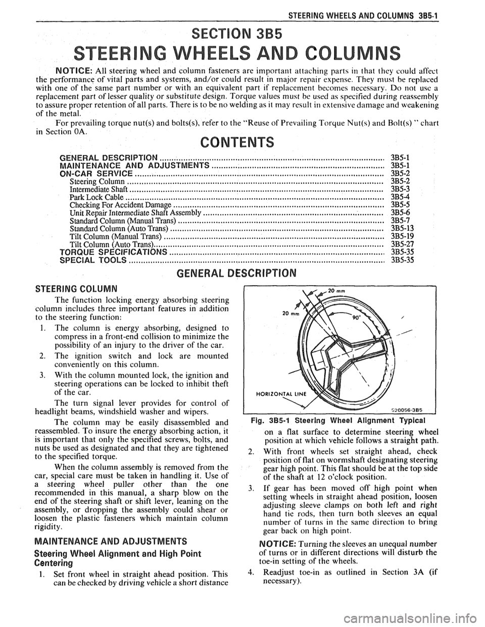
disassembled and Fig. 385-1 Steering Wheel Alignment ~ypical
reassembled. To insure the energy absorbing action, it
on a flat surface to determine steering wheel
is important that only the specified screws, bolts, and
position at which vehicle follows a straight path.
nuts be used as designated and that they are tightened
2. With front wheels set straight ahead, check to the specified torque.
position of flat on wormshaft designating steering
When the column assembly is removed from the
gear high point. This flat should be at the top side
car, special care must be taken in handling it. Use of
of the shaft at 12 o'clock position.
a steering puller other than the One 3, if gear has been moved off high when recommended in this manual, a sharp blow on the
setting wheels in straight ahead position, loosen
end of the steering shaft or shift lever, leaning on the
assembly, or dropping the assembly could shear or adjusting
sleeve clamps on both left and right
hand tie rods, then turn both sleeves an equal
loosen the plastic fasteners which maintain column
rigidity. number
of turns in the same direction
to bring
gear back
on high point.
MAINTENANCE AND ADJUSTMENTS NOTICE: Turning the sleeves an unequal number
Steering Wheel Alignment and High Point of turns or in different directions will disturb the
Centering toe-in setting of the wheels.
1. Set front wheel in straight ahead position, This 3. Readjust toe-in as outlined in Section 3A (if
can be checked by driving vehicle
a short distance necessary).
Page 1440 of 1825
TROUBLESHOOTING HINTS
0 Try the following checks before doing the
System Check.
1. Check the WIPER Fuse by visual
inspection.
2. Check that the three Wiper Motor mount-
ing bolts are clean and tight.
3. Check that the Wiper/Washer Switch con-
nector C240 is correctly mated.
4. If the Washer does not operate, check that:
- Washer reservoir is filled.
- Hoses are not pinched or kinked.
- Hoses are correctly attached.
- Nozzles are not clogged.
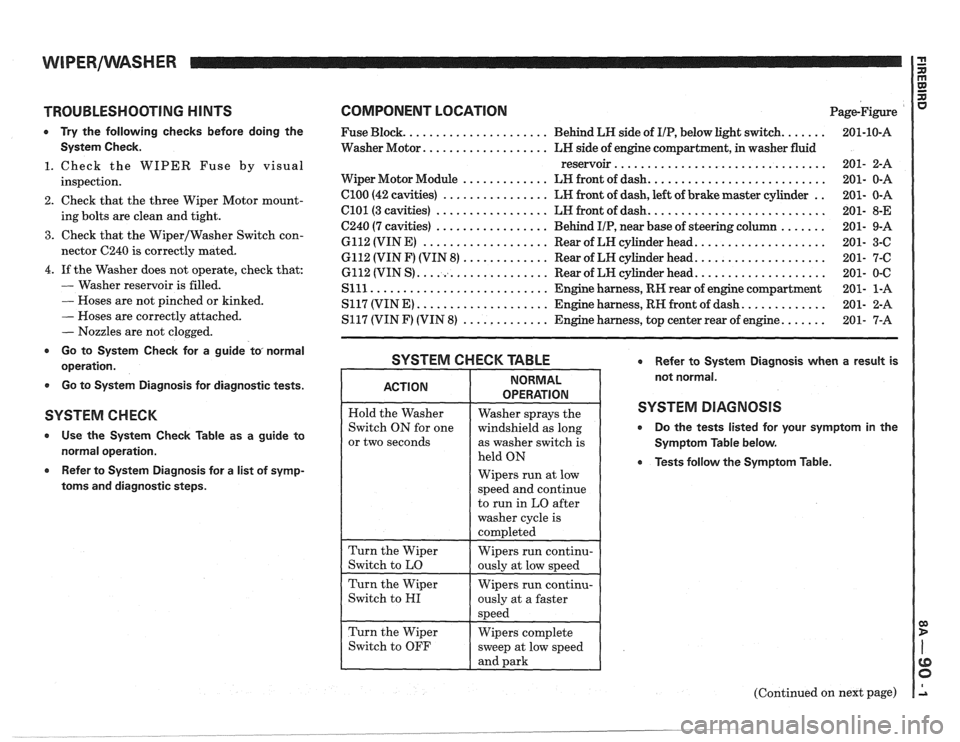
r Go to System Check for a guide to, normal
operation.
0 Go to System Diagnosis for diagnostic tests.
SYSTEM C H EGK
Use the System Check Table as a guide to
normal operation.
Refer to System Diagnosis for a list of symp-
toms and diagnostic steps.
COMPONENT LOCATION Page-Figure
...... ..................... Fuse Block. Behind LH side of IIP, below light switch.
Washer Motor.
.................. LH side of engine compartment, in washer fluid
reservoir
................................
.......................... Wiper Motor Module ............. LH front of dash.
.. Cl00 (42 cavities) ................ LH front of dash, left of brake master cylinder
.......................... C101 (3 cavities) ................. LH front of dash.
....... C240 (7 cavities) ................. Behind IIP, near base of steering column
................... 6112 (VIN E) ................... Rear of LH cylinder head.
................... 6112 (VIN F) (VIN 8) ............. Rear of LH cylinder head.
................... 6112 (VIN S) .................... Rear of LW cylinder head.
Slll ........................... Engine harness, RH rear of engine compartment
............ S117 (VIN E) .................... Engine harness, RH front of dash.
...... S117 (VIN F) (VIN 8) ............. Engine harness, top center rear of engine.
SYSTEM CHECK TABLE Refer to System Diagnosis when a result is
not normal.
SYSTEM DIAGNOSIS
0 Do the tests listed for your symptom in the
Symptom Table below.
0 Tests follow the Symptom Table.
or two seconds
Wipers run at low
(Continued on next page)
. __- ______ --___ -..- .
Page 1442 of 1825
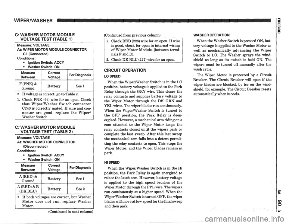
C: WASHER MOTOR MODULE
VOLTAGE TEST (TABLE
1 ) -
Measure: VOLTAGE
At: WIPER MOTOR MODULE CONNECTOR
Cl (Connected)
Conditions:
Ignition Switch: ACCY
Washer Switch: ON
Measure Correct For Diagnosis
Between Voltage
I (PNK'& I Battery I See 1 I Ground
If voltage is correct, go to Table 2.
1. Check PNK (94) wire for an open. Check
that WiperlWasher Switch connector
6240 is correctly mated. If wire and con-
nector are good, replace the Wiper1
Washer Switch.
CfWASHER MOTOR MODULE
VOLTAGE TEST (TABLE
2)
Measure: VOLTAGE
At:
VVASHER MOTOR CONNECTOR
(Disconnected)
Conditions:
Ignition Switch: ACCY
0 Washer Switch: ON
Measure
Between
I ::::ii 1 For Diagnosis I
I A(RED'& I Battery I See 1 I Ground
A (RED' & Battery
(DK BLU) See 2
If both voltages are correct, but Washer
Motor does not run, replace Washer
Motor.
(Continued in next column) (Continued
from previous column)
of Wiper Motor Module. (between
terrni-
nals F and D).
CIRCUIT OPERATION
LO SPEED
When the WiperlWasher Switch is in the LO
position, battery voltage is applied to the Park
Relay through the GRY wire. This closes the
relay contacts and supplies battery voltage to
the Wiper Motor through the DK GRN and
YEL wires. The wiper blades run continuously.
When the WiperIWasher Switch is turned to
the OFF position, the Park Relay is
deen-
ergized. However, a mechanical arm riding on a
cam attached to the Wiper Motor keeps the
relay contacts closed until the wipers park or
complete the last sweep. After this last sweep
the mechanical arm falls into a detent
perrnit-
ting the relay contacts to open. This stops the
Wiper Motor, and the Wiper blades remain in
park.
HI SPEED
When the WiperIWasher Switch is in the Hi
position, the Park Relay is again energized to
relase the latch arm. However, battery voltage
is applied to the high speed brushes of the
Wiper Motor through the PPL wire. The wipers
run continuously at a higher speed. When the
WiperlWasher Switch is turned OFF, the wiper
blades
will move at low speed for the final sweep
and then park.
VVASHER OPERATION
When the Washer Switch is pressed ON, bat-
tery voltage is applied to the Washer Motor
as
well as mechanically advancing the Wiper
Switch to LO. The Washer sprays the wind-
shield as long as its switch is held ON. The
wipers must be turned off manually after the
wash cycle.
The Wiper Motor is protected by a Circuit
Breaker. The Circuit Breaker
will open if the
wiper blades are blocked, by ice on the wind-
shield, for example. The Circuit Breaker resets
automatically when it cools.
Page 1444 of 1825
WIPERIWASHER: PULSE, CD4 I G n
TROUBLESHOOTING HINTS
Try the following checks before doing the
System Diagnosis.
1. Check the Wiper Fuse by visual inspection.
2. Check that the three
VViper Motor mounting
bolts are clean and tight.
3. Check that Wipermasher Switch connector
C240 and WiperIWasher Motor Module Con-
nectors are mated correctly.
4. If the Washer does not operate, check that:
- The Washer reservoir is filled.
- The hoses are not pinched or kinked.
- The hoses are correctly attached.
- The nozzles are not clogged.
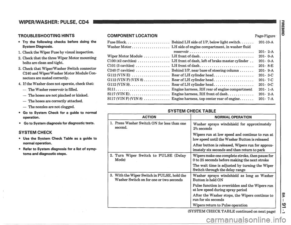
Go to System Check for a guide to normal
operation.
Go to System diagnosis for diagnostic tests.
SYSTEM CHECK
Use the System Check Table as a guide to
normal operation.
e Refer to System diagnosis for a list of symp-
toms and diagnostic steps.
COMPONENT LOCATION Page-Figure
...... ..................... Fuse Block. Behind LR side of IIP, below light switch.
.................. Washer Motor. LH side of engine compartment, in washer fluid
reservoir
................................
.......................... ............. Wiper Motor Module LN front of dash.
.. C100 (42 cavities) ................ LR front of dash, left of brake master cylinder
.......................... C101(3 cavities) ................. LH front of dash.
....... C240 (7 cavities) ................. Behind IIP, near base of steering column
................... 6112 (VIN E) ................... Rear of LN cylinder head.
................... 6112 (VIN F) (VIN 8) ............. Rear of LN cylinder head.
................... 6112 (VIN S) .................... Rear of LH cylinder head.
S111 ........................... Engine harness, RN rear of engine compartment
............ S117 (VINE) .................... Engine harness, RN front of dash.
...... S117 (VIN F) (VIN 8) ............. Engine harness, top center rear of engine.
SYSTEM CHECK TABLE
Wipers run at low speed and continue to run at
low speed until the Washer Button is released
Pulse function is overridden and the Wipers
run
After the Washer stops, the Wipers continue to
run for six seconds
I Wipers return to Pulse operation
(SYSTEM
CHECK TABLE continued on next page)
Page 1445 of 1825
WIPERIWASHER: PULSE, CD4 1 g
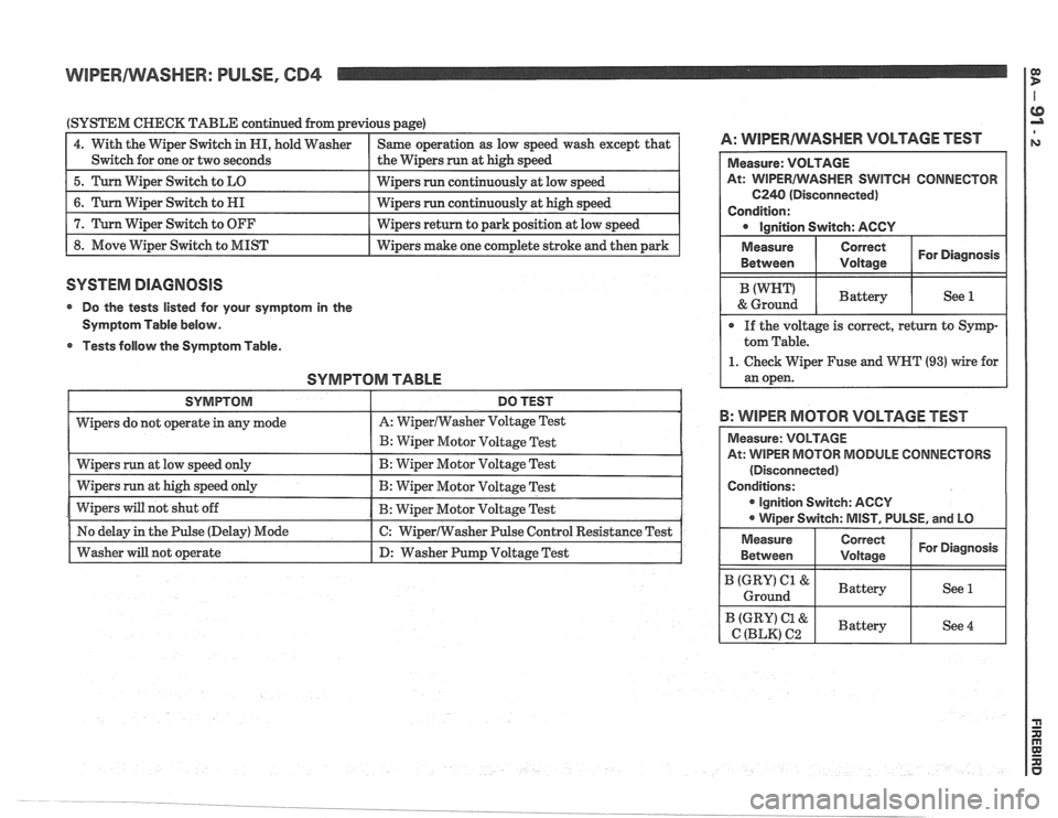
(SYSTEM CHECK TABLE continued from previous page)
1 4. With the Wiper Switch in HI, hold Washer I Same operation as low speed wash except that I A: WlPERAlVASHER VOLTAGE TEST
I Switch for one or two seconds I the Wipers run at high speed I
1 5. Turn Wiper Switch to LO I wipers run continuously at low speed I
1 8. Move Wiper Switch to MIST I Wipers make one complete stroke and then park I
6. Turn Wiper Switch to HI
7. Turn Wiper Switch to OFF
SYSTEM DIAGNOSIS
Wipers run continuously at high speed
Wipers return to park position at low speed
@ Do the tests listed for your symptom in the
Symptom Table below.
Tests
dollovv the Symptom Table.
SYMPTOM TABLE
SWITCH CONNECTOR
B: WIPER MOTOR VOLTAGE TEST
ODULE CONNECTORS
(Disconnected)
r ignition Switch: AGCY
Page 1447 of 1825
WIPERIWASHER: PULSE, CB4
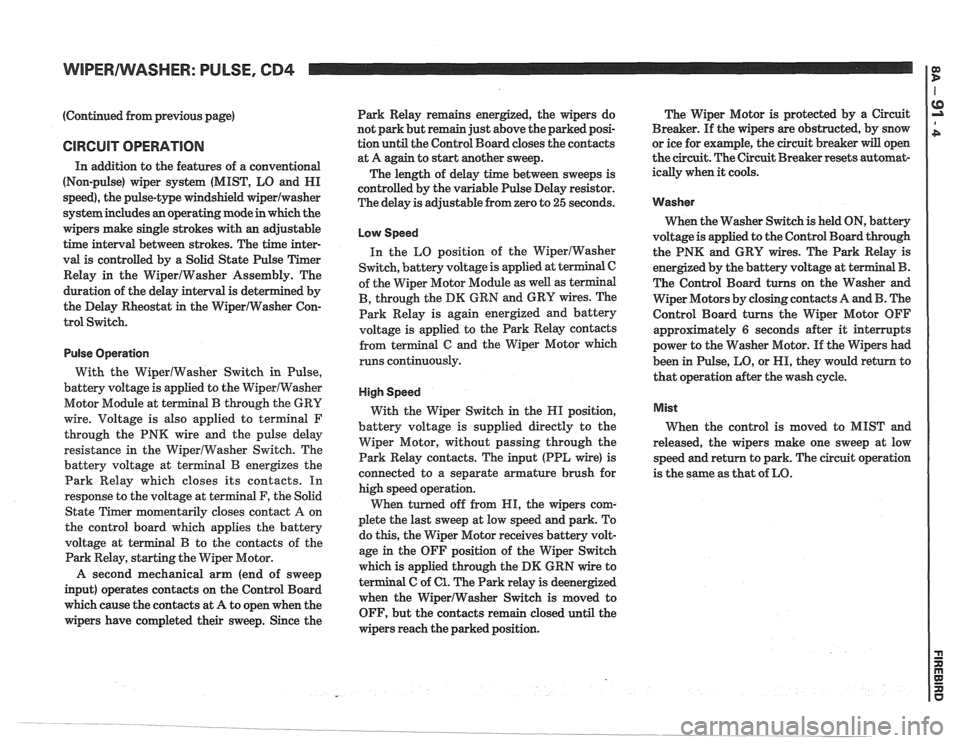
(Continued from previous page)
CIRCUIT OPERATION
In addition to the features of a conventional
(Non-pulse) wiper system (MIST, LO and HI
speed), the pulse-type windshield
wiperlwasher
system includes an operating mode in which the
wipers make single strokes with an adjustable
time interval between strokes. The time inter-
val is controlled by a Solid State Pulse Timer
Relay in the WiperIWasher Assembly. The
duration of the delay interval is determined by
the Delay Rheostat
in the WiperIWasher Con-
trol Switch.
Pulse Operation
With the WiperlWasher Switch in Pulse,
battery voltage is applied to the WiperlWasher
Motor Module at terminal
B through the GRY
wire. Voltage is also applied to
terminal F
through the PNK wire and the pulse delay
resistance in the WiperlWasher Switch. The
battery voltage at terminal
B energizes the
Park Relay which closes its contacts. In
response to the voltage at terminal F, the Solid
State Timer momentarily closes contact
A on
the control board which applies the battery
voltage at terminal
B to the contacts of the
Park Relay, starting the Wiper Motor.
A second mechanical arm (end of sweep
input) operates contacts on the Control Board
which cause the contacts at A to open when the
wipers have completed their sweep. Since the Park
Relay remains energized, the wipers do
not park but remain just above the parked posi-
tion until the Control Board closes the contacts
at A again to start
another sweep.
The length of delay time between sweeps is
controlled by the variable Pulse Delay resistor.
The delay is adjustable from zero to
25 seconds.
Low Speed
In the LO position of the WiperIWasher
Switch, battery voltage is applied at terminal C
of the Wiper Motor Module as well as terminal
B, through the DK GRN and GRY wires. The
Park Relay is again energized and battery
voltage is applied to the Park Relay contacts
from terminal
G and the Wiper Motor which
runs continuously.
High Speed
With the Wiper Switch in the HI position,
battery voltage is supplied directly to the
Wiper Motor, without passing through the
Park Relay contacts. The input (PPL wire) is
connected to a separate armature brush for
high speed operation.
When turned off from HI, the wipers com-
plete the last sweep at low speed and park. To
do this, the Wiper Motor receives battery volt-
age
in the OFF position of the Wiper Switch
which is applied through the
DM GRN wire to
terminal C of
61. The Park relay is deenergized
when the WiperlWasher Switch
is moved to
OFF, but the contacts remain closed until the
wipers reach the parked position. The
Wiper Motor is protected by a Circuit
Breaker. If the wipers are obstructed, by snow
or ice for example, the circuit breaker
will open
the circuit. The Circuit Breaker resets automat-
ically when
it cools.
Washer
When the Washer Switch is held ON, battery
voltage is applied to the Control Board through
the PNK and GRY wires. The Park Relay is
energized by the battery voltage at ter
The Control Board turns on the Washer and
Wiper Motors by closing contacts A and
B. The
Control Board turns the Wiper Motor OFF
approximately
6 seconds after it interrupts
power to the Washer Motor. If the Wipers had
been in Pulse, LO, or HI, they would return to
that operation after the wash cycle.
Mist
When the control is moved to MIST and
released, the wipers make one sweep at low
speed and return to park. The circuit operation
is the same as that of LO.
Page 1600 of 1825
LIGHTING SYSTEMS AND HORNS 8B-I
SECTION 8B
NG SYSTEMS AND HORNS
CONTENTS
........................... GENERAL DESCRIPTION 8B-1
Exterior Lights
....................... ................... Back-up Lights .. 8B- 1
Center High-Mounted Stoplight .................... 8B-1
Exterior Light Monitor .................................. 8B-1
............................ .................... Fog Lights .. 8B-1
Front Parking/Turn Signal Lights ................ 8B-2
............................... Hazard Flashers .. ........ 8B-2 .................................................... Headlights 8B-2
License Plate Lights ..................................... 8B-2
Light Switch ............................................... 8B-2
............... Rear Tail/Stop/Turn Signal Lights 8B-2
Sidemarker Lights ........................................ 8B-2
Turn Signals .......................................... 8B-2
......................... Underhood Light ... ........ 8B-2
Horns .......................................................... 8B-3
....................................... ON-CAR SERVICE 8B-3
Exterior Lights
............................................. Back-up Lights 8B-3
Center High-Mounted Stoplight .................... 8B-3
Fog Lights .................................................... 8B-4
Front Parking/Turn Signal Lights ................ 8B-4
Hazard Flasher .............................................. 8B-5
....................................................... Headlights 8B-5
License Plate Lights ..................................... 8B-7
............... Rear Tail/Stop/Turn Signal Lights 8B-8
.......................................... Sidemarker Lights 8B-8
................... ............... Turn Signal Flasher .. 8B-9
......................................... Underhood Light 8B-9
Horns ................................................................. 8B-9
REPLACEMENT BULB
.................................... SPECIFICATIONS 8B- 10
The following information, previously shown in this section,
has been moved to the sections shown.
Back-up Lights Switch
............................. ... ............................................................................ 7
................................................................................................................................. Fuse Block 8A
Ignition Switch ........................................................................................................................... 3B
Interior Lights
................................................................................................................... 8A, 8C
Neutral Start Switch ..................................................................................................................... 7
Parking Brake Warning Switch
......................... ... .................................................................... 5
........................................................................ Seat Belt, Key and Headlight Warning Alarm 8A
Stoplight Switch .......................... .. ............................................................................................... 5
Windshield
Wipers/Washers .................................................................................................... 8E
GENERAL DESCRIPTION
The exterior lighting system includes the
headlights (and headlight motors to raise or lower the
headlights), front
parkinghurn signal lights, front
cornering lights, fog lights, rear
tail/stop/turn signal
lights, back-up lights, license plate lights, center
high-mounted stoplight, and the underhood light; it
also includes all associated wiring, controls and related
hardware for these lights.
BACK-UP LIGHTS - The back-up lights are
next to the rear license plate. They will come on when
the transmission is shifted to Reverse. On cars with an
automatic transmission, the back-up lights are
activated by the neutral start switch. On cars with a
manual transmission, they are activated by a separate
back-up light switch on the transmission. For more
information, see Section 7.
CENTER HIGH-MOUNTED STOPLIGHT-
The center high-mounted stoplight, in the center of the
rear spoiler, will come on whenever the brake pedal is
pushed down. The light is powered separately from the rear
tail/stop/turn signal
lights through a separate
circuit in the stoplight switch (see Section
8A).
EXTERIOR LIGHT MONITOR - The Driver
Information Center, on cars so equipped, also monitors
certain front and rear lights. When a bulb burns out,
the message
"FRONT LAMP" or "REAR LAMP"
will appear in the DIC display, and a light will come
on to indicate which bulb has burned out. For more
information, see Section
8A.
FOG LIGHTS -The fog light switches are to the
left of the steering column on the edge of the
instrument panel. To use the fog lights, first turn on the
headlights or parking lights. Then, push the middle
switch (with the fog light symbol) to turn on the fog
lights. Push the left
("OFF") switch to turn off the fog
lights.
The fog lights should not be used as a substitute
for the headlights.
Switching to high-beam headlights will turn off
the fog lights; switching back to low-beams will turn
the fog lights on again.
Page 1628 of 1825
WINDSI4IELD WIPER SYSTEMS - F CARLINE 8E -1
SECTION 8E
F CARL
ELD W PER-WASHER SYSTEM
PULSE & STANDARD
CONTENTS
General Description ....................... 8E -1 Park Switch Replacement ............... .8E -3
Wiper and Washer Operation
............ 8E -1
Wiper Motor Replacement .............. 8E -1 1
Pulse Windshield Wiper System
........... 8E -1
Wiper Transmission .................... 8E -1 1
Diagnosis Wiper Arm
........................... 8E -12
Diagnostic Procedures
................... 8E -2 Wiper Blade ........................... 8E -13
Wiper Motor
........................... 8E -2 Wiper Blade Insert ..................... 8E -14
Washer Pump
.......................... 8E -2 Windshield Washer ..................... 8E -15
........................ Diagnostic Chart 8E -3 Unit Repair
On-Car Service Gear Replacement
..................... 8E - 15
Washer Pump Replacement .............. 8E -3 Wiper-Washer Nozzle and Container
Wiper Cover Replacement
............... 8E -3 Mounting ........................... 8E -1 8
GENERAL DESCRIPTION
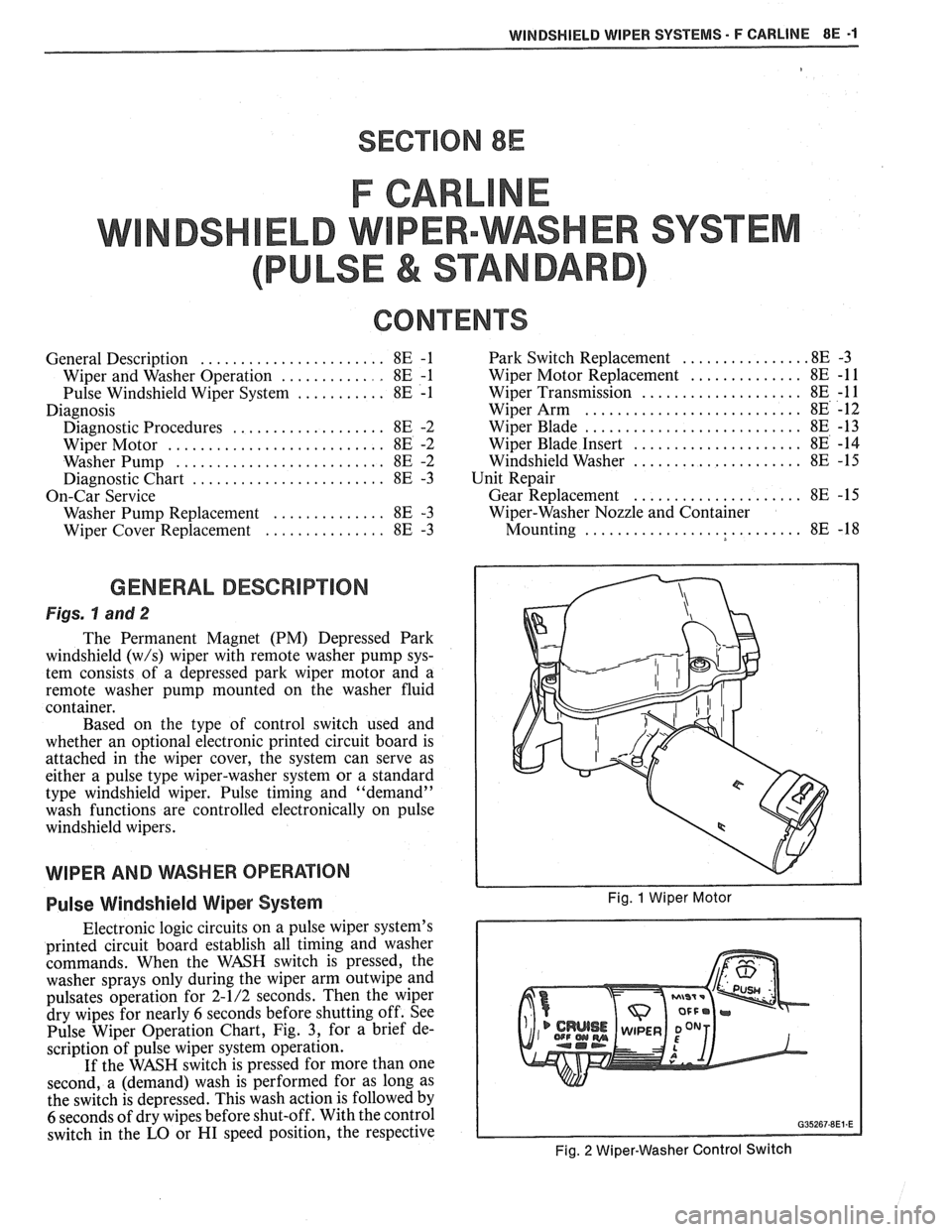
Figs. hand 2
The Permanent Magnet (PM) Depressed Park
windshield
(w/s) wiper with remote washer pump sys-
tem consists of a depressed park wiper motor and a
remote washer pump mounted on the washer fluid
container.
Based on the type of control switch used and
whether an optional electronic printed circuit board is
attached in the wiper cover, the system can serve as
either a pulse type wiper-washer system or a standard
type windshield wiper. Pulse timing and "demand"
wash functions are controlled electronically on pulse
windshield wipers.
WIPER AND WSHER OPERAflON
Pulse Windshield Wiper System Fig. 1 Wiper Motor
Electronic logic circuits on a pulse wiper system's
printed circuit board establish all timing and washer
commands. When the WASH switch is pressed, the
washer sprays only during the wiper arm
outwipe and
pulsates operation for 2-1/2 seconds. Then the wiper
dry wipes for nearly
6 seconds before shutting off. See
Pulse Wiper Operation Chart, Fig.
3, for a brief de-
scription of pulse wiper system operation.
If the WASH switch is pressed for more than one
second, a (demand) wash is performed for as long as
the switch is depressed. This wash action is followed by
6 seconds of dry wipes before shut-off. With the control
switch in the
LO or HI speed position, the respective
Fig. 2 Wiper-Washer Control Switch
Page 1639 of 1825
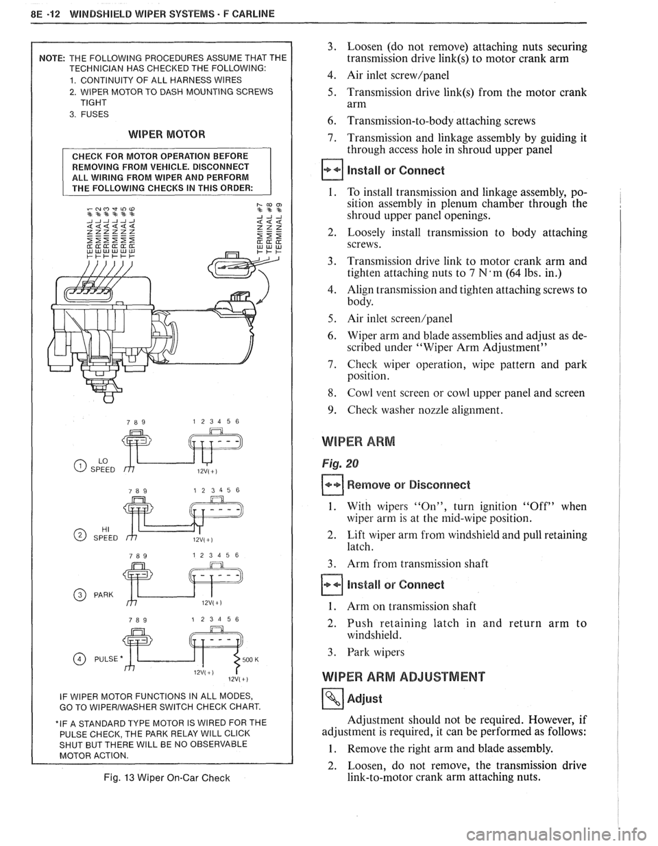
8E -12 WINDSHIELD WIPER SYSTEMS. F CAWLINE
2. WIPER MOTOR TO DASH MOUNTING SCREWS
WIPER MOTOR
REMOVING FROM VEHICLE. DISCONNECT
ALL WIRING FROM WIPER AND PERFORM
GO TO WlPERlWASHER SWITCH CHECK CHART.
E PARK RELAY
WlLL CLICK WlLL BE NO OBSERVABLE
Fig. 13 Wiper On-Gar Check
3. Loosen (do not remove) attaching nuts securing
transmission drive
link(s) to motor crank arm
4. Air inlet screw/panel
5. Transmission drive link(s) from the motor crank
arm
6. Transmission-to-body attaching screws
7. Transmission and linkage assembly by guiding it
through access hole in shroud upper panel
install or Connect
1. To install transmission and linkage assembly, po-
sition assembly in plenum chamber through the
shroud upper panel openings.
2. Loosely install transmission to body attaching
screws.
3. Transmission drive link to motor crank arm and
tighten attaching nuts to
7 N'm (64 lbs. in.)
4. Align transmission and tighten attaching screws to
body.
5. Air inlet screen/panel
6. Wiper arm and blade assemblies and adjust as de-
scribed under "Wiper Arm Adjustment"
7. Check wiper operation, wipe pattern and park
position.
8. Cowl vent screen or cowl upper panel and screen
9. Check washer nozzle alignment.
WIPER ARM
Fig. 20
Remove or Disconnect
1. With wipers "On", turn ignition "Off" when
wiper arm is at the mid-wipe position.
2. Lift wiper arm from windshield and pull retaining
latch.
3. Arm from transmission shaft
Install or Connect
1. Arm on transmission shaft
2. Push retaining latch in and return arm to
windshield.
3. Park wipers
WIPER ARM ADJUSTMENT
Adjust
Adjustment should not be required. However, if
adjustment is required, it can be performed as follows:
1. Remove the right arm and blade assembly.
2. Loosen, do not remove, the transmission drive
link-to-motor crank arm attaching nuts.
Page 1640 of 1825
WINDSHIELD WIPER SYSTEMS - F CARLINE 8E -13
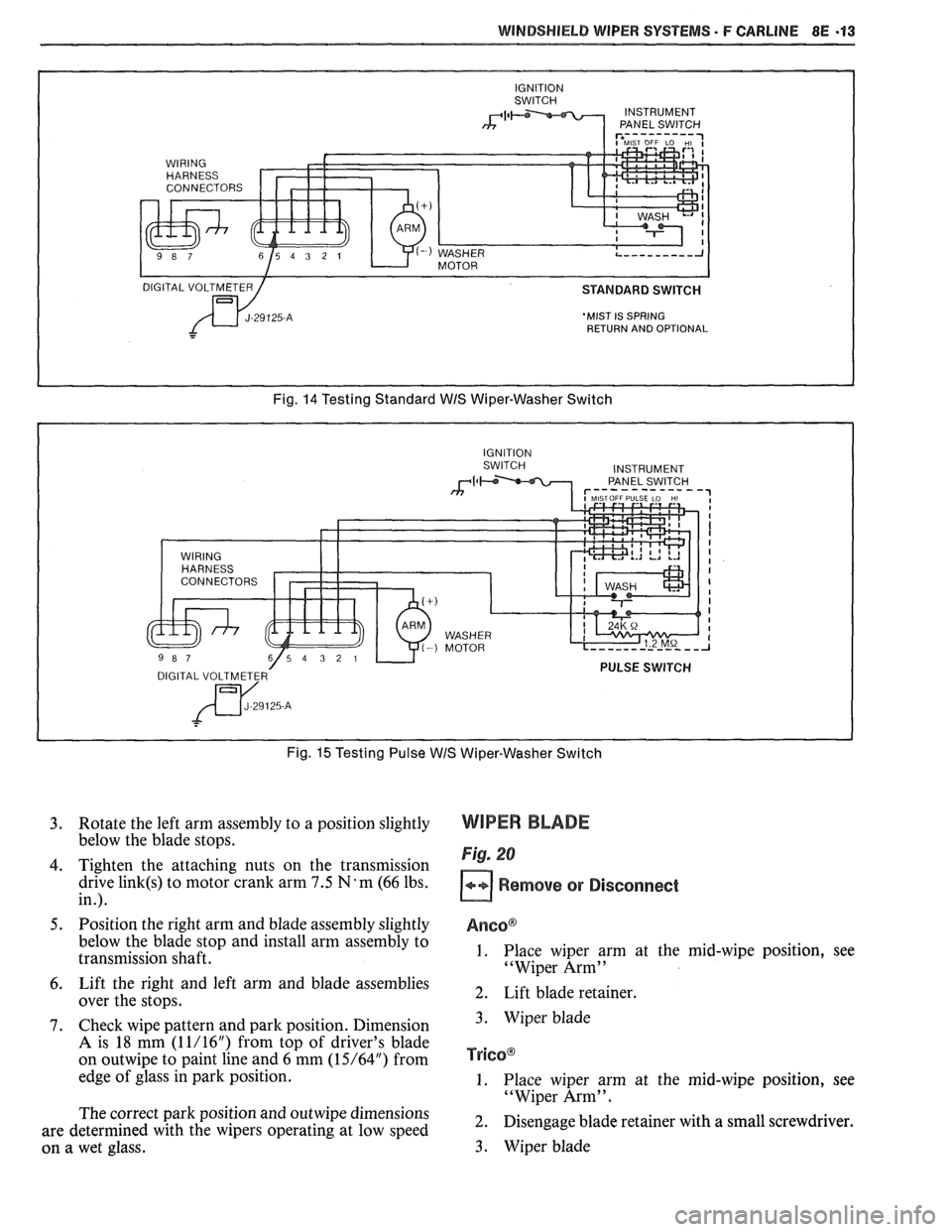
'MIST IS SPRING
RETURN AND OPTIONAL
Fig. 14 Testing Standard WIS Wiper-Washer Switch
Fig.
15 Testing Pulse WIS Wiper-Washer Switch
3. Rotate the left arm assembly to a position slightly
below the blade stops.
4. Tighten the attaching nuts on the transmission
drive
link(s) to motor crank arm 7.5 N'm (66 lbs.
in.).
5. Position the right arm and blade assembly slightly
below the blade stop and install arm assembly to
transmission shaft.
6. Lift the right and left arm and blade assemblies
over the stops.
7. Check wipe pattern and park position. Dimension
A is 18 mm (1 1/16") from top of driver's blade
on
outwipe to paint line and 6 mm (15/64") from
edge of glass in park position.
The correct park position and
outwipe dimensions
are determined with the wipers operating at low speed
on a wet glass.
WIPER BLADE
Fig. 20
Remove or Disconnect
Anso@
1. Place wiper arm at the mid-wipe position, see
"Wiper Arm"
2. Lift blade retainer.
3. Wiper blade
TY~GO@
1. Place wiper arm at the mid-wipe position, see
"Wiper Arm".
2. Disengage blade retainer with a small screwdriver.
3. Wiper blade