headlamp PONTIAC G5 2010 Owner's Manual
[x] Cancel search | Manufacturer: PONTIAC, Model Year: 2010, Model line: G5, Model: PONTIAC G5 2010Pages: 422, PDF Size: 2.22 MB
Page 266 of 422

Buying New Tires........................................ .6-64
Different Size Tires and Wheels ......................6-66
Uniform Tire Quality Grading ..........................6-67
Wheel Alignment and Tire Balance ..................6-68
Wheel Replacement ..................................... .6-68
Tire Chains ................................................. .6-70
If a Tire Goes Flat ....................................... .6-70
Tire Sealant and Compressor Kit ....................6-72
Tire Sealant and Compressor Kit Storage .........6-79
Changing a Flat Tire .................................... .6-80
Removing the Spare Tire and Tools ................6-81
Removing the Flat Tire and Installing the Spare Tire ............................................... .6-86
Storing a Flat or Spare Tire and Tools ............6-90
Compact Spare Tire ..................................... .6-93
Appearance Care ........................................... .6-94
Interior Cleaning .......................................... .6-94
Fabric/Carpet .............................................. .6-95
Leather ...................................................... .6-96
Instrument Panel, Vinyl, and Other Plastic Surfaces ................................................. .6-96
Care of Safety Belts ..................................... .6-96
Weatherstrips .............................................. .6-97Washing Your Vehicle
.................................. .6-97
Cleaning Exterior Lamps/Lenses .....................6-97
Finish Care ................................................. .6-98
Windshield and Wiper Blades .........................6-98
Aluminum or Chrome-Plated Wheels and Trim ................................................. .6-99
Tires ........................................................ .6-100
Sheet Metal Damage .................................. .6-100
Finish Damage .......................................... .6-100
Underbody Maintenance ...............................6-100
Chemical Paint Spotting ...............................6-100
Vehicle Identi�cation .................................... .6-101
Vehicle Identification Number (VIN) ................6-101
Service
Parts Identification Label ...................6-101
Electrical System ......................................... .6-102
Add-On Electrical Equipment .........................6-102
Headlamp Wiring ....................................... .6-102
Windshield Wiper Fuses ...............................6-102
Power Windows and Other Power Options ......6-102
Fuses and Circuit Breakers ..........................6-103
Floor Console Fuse Block ............................6-103
Engine Compartment Fuse Block ...................6-105
Capacities and Speci�cations ........................6-109
Section 6 Service and Appearance Care
6-2
Page 302 of 422

Notice:If the jumper cables are connected or
removed in the wrong order, electrical shorting may
occur and damage the vehicle. The repairs would
not be covered by the vehicle warranty. Always
connect and remove the jumper cables in the correct
order, making sure that the cables do not touch
each other or other metal.
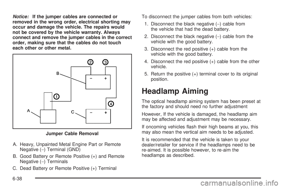
A. Heavy, Unpainted Metal Engine Part or Remote Negative (−) Terminal (GND)
B. Good Battery or Remote Positive (+) and Remote Negative (−) Terminals
C. Dead Battery or Remote Positive (+) Terminal To disconnect the jumper cables from both vehicles:
1. Disconnect the black negative ( −) cable from
the vehicle that had the dead battery.
2. Disconnect the black negative ( −) cable from the
vehicle with the good battery.
3. Disconnect the red positive (+) cable from the vehicle with the good battery.
4. Disconnect the red positive (+) cable from the other vehicle.
5. Return the positive (+) terminal cover to its original position.
Headlamp Aiming
The optical headlamp aiming system has been preset at
the factory and should need no further adjustment
However, If the vehicle is damaged, the headlamp aim
may be affected and adjustment may be necessary.
If oncoming vehicles flash their high beams at you, this
may also mean the vertical aim needs to be adjusted.
It is recommended that the vehicle is taken to your
dealer/retailer for service if the headlamps need to be
re-aimed. It is possible however, to re-aim the
headlamps as described.
Jumper Cable Removal
6-38
Page 303 of 422

The vehicle should be:
•Placed so the headlamps are 25 ft. (7.6 m) from a
light colored wall.
•On a perfectly level surface which is level all the
way to the wall.
•Placed so it is at a right angle to the wall.
•Clear of any snow, ice, or mud on it.
•Fully assembled, with the tires properly inflated, and
all other work stopped while headlamp aiming is
being done.
•Normally loaded with a full tank of fuel, with the
spare tire in the proper location, and one person
or 160 lbs (75 kg) on the driver seat.Headlamp aiming is done with the vehicle’s low-beam
headlamps. The high-beam headlamps will be correctly
aimed if the low-beam headlamps are aimed properly.
To adjust the vertical aim on the headlamps:
1. Open the hood. See Hood Release on page 6-11 .
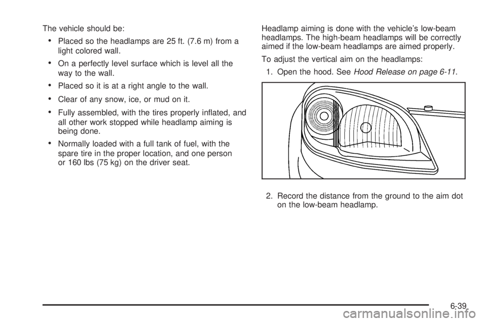
2. Record the distance from the ground to the aim dot on the low-beam headlamp.
6-39
Page 304 of 422

3. At the wall, measure from the ground upward (A) tothe recorded distance from Step 2 and mark it.
4. Draw or tape a horizontal line (B) on the wall the width of the vehicle at the height of the mark in
Step 3.
Notice: Do not cover a headlamp to improve beam
cut-off when aiming. Covering a headlamp may
cause excessive heat build-up which may cause
damage to the headlamp.
5. Turn on the low-beam headlamps and place a piece of cardboard in front of the headlamp not
being adjusted. Do not place it directly on the
headlamp. This allows only the beam of light from
the headlamp being adjusted to be seen on the
flat surface. 6. Locate the vertical headlamp aiming screws, which
are under the hood near each headlamp assembly.
The adjustment screw can be turned with a 6 mm
socket wrench.
7. Turn the vertical aiming screw until the headlamp beam is aimed to the horizontal tape line. Turn it
clockwise or counterclockwise to raise or lower the
angle of the beam.
6-40
Page 305 of 422

8. Make sure that the light from the headlamp ispositioned at the bottom edge of the horizontal tape
line. The lamp on the left (A) shows the correct
headlamp aim. The lamp on the right (B) shows the
incorrect headlamp aim.
9. Repeat Steps 6 through 8 for the opposite headlamp.
Bulb Replacement
For the proper type of replacement bulbs, see
Replacement Bulbs on page 6-47 .
For any bulb changing procedure not listed in this
section, contact your dealer/retailer.
Halogen Bulbs
{WARNING:
Halogen bulbs have pressurized gas inside and
can burst if you drop or scratch the bulb. You or
others could be injured. Be sure to read and follow
the instructions on the bulb package.
6-41
Page 306 of 422

Headlamps, Front Turn Signal,
Sidemarker, and Parking Lamps
A. Front Turn Signal/Parking Lamp
B. Sidemarker
C. Headlamp To replace one of these bulbs:
1. Open the hood. See Hood Release on page 6-11 .
2. Remove the two bolts from the headlamp assembly.
3. Remove the two fasteners from the fascia. Assistance may be needed for Steps 4 and 5.
4. Pull the front fascia back.
6-42
Page 307 of 422

5. Pull the headlamp assembly up at an angle andtowards the radiator to remove it.
6. Disconnect the bulb base from the wiring harness by lifting the locking tab.
7. Disconnect the wiring harness from the bulb socket.
8. Remove the retainer by turning it counterclockwise.
9. Turn the bulb socket for the headlamp, front turn signal, or parking lamp counterclockwise.
For the sidemarker bulb, use a tool to assist
in turning the bulb socket.
10. Pull the old bulb out of the socket.
11. Install a new bulb.
12. Reinstall the bulb assembly by reversing Steps 1 through 9.
When reinstalling the headlamp assembly, first
make sure that the wiring harness is in its original
position. If not, the headlamp assembly will not
fit correctly.
Align the two tabs on the bottom of the assembly
that fit into two slots in the headlamp assembly
bracket.Center High-Mounted Stoplamp
(CHMSL)
To replace a CHMSL bulb: 1. Open the trunk.
2. Press the tabs to release the bulb assembly.
3. Pull the bulb assembly down to access the bulbs.
4. Pull the old bulb straight out.
6-43
Page 311 of 422

6. Push and turn the license plate lamp away fromyou through the opening.
7. Reinstall the two screws holding the license plate lamp.
Replacement Bulbs
Exterior Lamps Bulb Number
Back-Up Lamps 921
Center High-Mounted
Stoplamp (CHMSL) 912
Front Parking/Turn Signal Lamps 3157KX
Halogen Headlamps,
High/Low-Beam 9007 LL
License Plate Lamp and
Sidemarker 194
Stoplamp, Taillamp and Turn
Signal Lamps 3057KX
For replacement bulbs not listed here, contact your
dealer/retailer.
Windshield Wiper Blade
Replacement
Windshield wiper blades should be inspected for wear
or cracking. See Scheduled Maintenance on page 7-3
for more information on wiper blade inspection. Replacement blades come in different types and are
removed in different ways. For proper type and length,
see
Maintenance Replacement Parts on page 7-12 .
Here is how to remove the wiper blades:
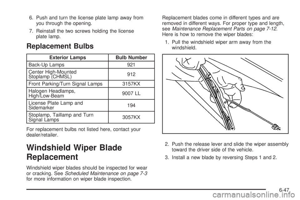
1. Pull the windshield wiper arm away from the windshield.
2. Push the release lever and slide the wiper assembly toward the driver side of the vehicle.
3. Install a new blade by reversing Steps 1 and 2.
6-47
Page 333 of 422

Each new wheel should have the same load-carrying
capacity, diameter, width, offset, and be mounted
the same way as the one it replaces.
If you need to replace any of your wheels, wheel bolts,
wheel nuts, or Tire Pressure Monitor System (TPMS)
sensors, replace them only with new GM original
equipment parts. This way, you will be sure to have the
right wheel, wheel bolts, wheel nuts, and TPMS
sensors for your vehicle.
{WARNING:
Using the wrong replacement wheels, wheel bolts,
or wheel nuts on your vehicle can be dangerous. It
could affect the braking and handling of your
vehicle, make your tires lose air and make you
lose control. You could have a collision in which
you or others could be injured. Always use the
correct wheel, wheel bolts, and wheel nuts for
replacement.Notice:
The wrong wheel can also cause problems
with bearing life, brake cooling, speedometer or
odometer calibration, headlamp aim, bumper height,
vehicle ground clearance, and tire or tire chain
clearance to the body and chassis.
See Changing a Flat Tire on page 6-80 for more
information.
Used Replacement Wheels
{WARNING:
Putting a used wheel on the vehicle is dangerous.
You cannot know how it has been used or how far
it has been driven. It could fail suddenly and
cause a crash. If you have to replace a wheel, use
a new GM original equipment wheel.
6-69
Page 366 of 422

Electrical System
Add-On Electrical Equipment
Notice:Do not add anything electrical to the
vehicle unless you check with your dealer/retailer
�rst. Some electrical equipment can damage
the vehicle and the damage would not be covered
by the vehicle’s warranty. Some add-on electrical
equipment can keep other components from
working as they should.
Add-on equipment can drain the vehicle battery, even if
the vehicle is not operating.
The vehicle has an airbag system. Before attempting to
add anything electrical to the vehicle, see Servicing
Your Airbag-Equipped Vehicle on page 2-69 andAdding
Equipment to Your Airbag-Equipped Vehicle on
page 2-70.
Headlamp Wiring
The headlamp wiring is protected by fuses. Should the
headlamps fail to function, have the headlamp system
checked right away.
Windshield Wiper Fuses
The windshield wiper motor is protected by a circuit
breaker and a fuse. If the motor overheats due to heavy
snow, etc., the wiper will stop until the motor cools. If
the overload is caused by some electrical problem, have
it fixed.
Power Windows and Other Power
Options
Fuses in the fuse block protect the power windows.
When the current load is too heavy, the fuse opens
protecting the circuit until the problem is fixed.
6-102