PORSCHE 911 CARRERA 2005 5.G Manual PDF
Manufacturer: PORSCHE, Model Year: 2005, Model line: 911 CARRERA, Model: PORSCHE 911 CARRERA 2005 5.GPages: 282, PDF Size: 4.34 MB
Page 71 of 282
Controls, Instruments
71
Page 72 of 282
72
Controls, Instruments
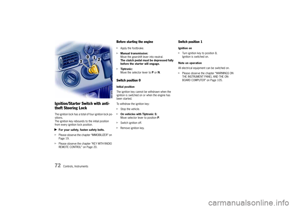
Ignition/Starter Switch with anti-
theft Steering LockThe ignition lock has a total of four ignition lock po-
sitions.
The ignition key rebounds to the initial position
from every ignition lock position.
fFor your safety, fasten safety belts.
fPlease observe the chapter “IMMOBILIZER” on
Page 19.
fPlease observe the chapter “KEY WITH RADIO
REMOTE CONTROL” on Page 20.
Before starting the enginefApply the footbrake.
fManual transmission:
Move the gearshift lever into neutral.
The clutch pedal must be depressed fully
before the starter will engage.
fTiptronic:
Move the selector lever to P or N.Switch position 0 Initial position
The ignition key cannot be withdrawn when the
ignition is switched on or when the engine has
been started.
To withdraw the ignition key:
fStop the vehicle.
fOn vehicles with Tiptronic S:
Move selector lever to position P.
fSwitch ignition off.
fRemove ignition key.
Switch position 1 Ignition on
fTurn ignition key to position 1.
Ignition is switched on.
Note on operation
All electrical equipment can be switched on.
fPlease observe the chapter “WARNINGS ON
THE INSTRUMENT PANEL AND THE ON-
BOARD COMPUTER” on Page 105.
Page 73 of 282

Controls, Instruments
73
Switch position 2Start engine
fTurn ignition key to ignition lock position 2.
fPlease observe the chapter “STARTING PRO-
CEDURES” on Page 74.Switch position 3Ignition off
fTurn ignition key to ignition lock position 3.
Locking the steering columnAutomatic locking
The steering column is automatically locked when
the ignition key is withdrawn from the ignition lock.
Warning!
Risk of an accident.
The steering wheel will lock and will cause
loss of steering.
fNever remove key from the ignition lock or turn
the key off while the vehicle is moving.
fAlways withdraw the ignition key when leav-ing the vehicle.Automatic unlocking
The steering column is automatically unlocked
when the ignition key is inserted into the ignition
lock.
Note
fTo avoid battery run-down, always remove the
ignition key from the ignition lock.
Please observe the chapter “BATTERY” on
Page 236.
Gong If you leave the key in the ignition/steering lock, a
gong will sound when the driver’s door is opened.
This is a reminder to remove the key.
Page 74 of 282

74
Controls, Instruments
Starting Procedures fPlease observe the chapter “IMMOBILIZER” on
Page 19.
fPlease observe the chapter “EMISSION CONT-
ROL SYSTEM” on Page 191.
Warning!
Serious injury may result if you are involved
in a collision without having fastened the
safety belts.
fFasten safety belts before driving away. Before starting the engine fApply the footbrake.
fManual transmission:
Move the gearshift lever into neutral.
The clutch pedal must be depressed fully
before the starter will engage.
fTiptronic:
Move the selector lever to P or N.
Temperature sensors on the engine automatically
provide the correct fuel/air mixture required for
starting.
Therefore, it is not necessary to depress the
accelerator pedal while starting a cold or a
warm engine.
Starting the enginefTurn ignition key to ignition lock position 2.
fAs soon as the engine starts, release the igni-
tion key.
The first operation of the starter is ended automat-
ically when the engine starts.
If the engine does not start, subsequent starter
operations will not be ended automatically.
If the engine fails to start after 10 or 15 seconds
of cranking:
fWait about 10 seconds before engaging the
starter again.
fWhen starting the engine, be ready to drive
immediately.
Drive vehicle at moderate speeds and avoid
engine speeds above 4,200 rpm during the
first 5 minutes.
fDo not let the engine idle to warm up.
Danger!
Engine exhaust fumes have many compo-
nents which you can smell. They also contain
carbon monoxide (CO), which is a colorless
and odorless gas.
Carbon monoxide can cause unconscious-
ness and even death if inhaled.
fNever start or let the engine run in an en-
closed, unventilated area.
It is not recommended to sit in your car for pro-
longed periods with the engine on and the car
not moving.
An unattended vehicle with a running engine
is potentially hazardous.
If warning lights should come on to indicate
improper operation, they would go unno-
ticed.
fNever leave the engine idling unattended.
Danger of fire.
fDo not park or operate the vehicle in areas
where the hot exhaust system may come in
contact with dry grass, brush, fuel spill or oth-
er flammable material.
fIf your car catches on fire for any reason, call
the fire department.
Do not endanger your life by attempting to put out the fire.
Page 75 of 282

Controls, Instruments
75
Stopping Engine fTurn key back to position 3.
fDo not stop engine immediately after hard or
extended driving.
Keep engine running at increased idle for
about two minutes to prevent excessive heat
build-up before turning off engine.
fTo avoid battery run-down, always remove the
ignition key from the ignition lock.
fMake sure that when you leave the car, even
briefly, you have withdrawn the ignition key.
fEngage the steering lock by moving the steer-
ing wheel to the left or right.
Turn the steering wheel to the locking position
before you switch off the engine so that you
don’t have to exert yourself when locking or
unlocking the steering.
Warning!
Danger of injury. Hot engine compartment
components can burn skin on contact.
fBefore working on any part in the engine com-
partment, turn the engine off and let it cool down sufficiently.
Engine-compartment blower,
radiator fan The radiator and radiator fans are in the front of
the car.
The engine-compartment blower is mounted on
the engine compartment lid.
Warning!
Risk of injury.
After the engine is switched off, the engine-
compartment temperature is monitored for
approx. 30 minutes.
During this period, and depending on tem-
perature, the engine-compartment blower
may continue to run or start to run.
fCarry out work in these areas only with the en-
gine off, the ignition off, and exercise extreme
caution.
Risk of injury. The radiator fans in the front
end of the car may be operating or
unexpectedly start operating when the
engine is switched on.
fCarry out work in these areas only with the en-gine switched off.
Automatic garage door The ignition system in your Porsche may interfere
with your electronically operated garage door.
fTo check this, drive your Porsche close to the
garage door. Make sure not to interfere with
the operating range of the door.
fRun the engine at different speeds.
If the garage door opens or closes without you op-
erating the garage door unit in your car, contact
the dealer who installed the automatic garage
door to have the frequency and/or coding of the
garage door signal changed or modified.
Page 76 of 282

76
Controls, Instruments
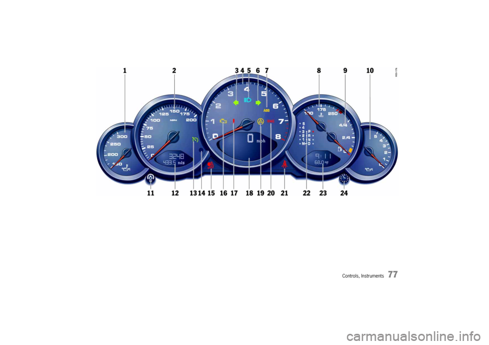
Instrument Panel USA Models Also refer to the corresponding chapters in
the Owner’s Manual.
1. Engine oil temperature gauge
2. Speedometer with analogue display
3. Turn signal indicator light, left
4. Tachometer
5. High beam indicator light
6. Turn signal indicator light, right
7. ABS warning light
8. Cooling system
Temperature gauge, warning light
9. Fuel
Level gauge, warning light
10.Engine oil pressure gauge
11.Adjustment button for instrument illumination
and trip counter
12.Odometer and daily trip mileage display
13.Automatic speed control indicator light14.Light sensor for instrument illumination
15.Airbag warning light
16.Emission control warning light
(Check Engine)
17.Central warning light
18.On-board computer display
19.Porsche Stability Management
Multifunctional PSM light
20.Brake warning light
21.Safety belt warning light
22.Tiptronic indicator
23.Clock and outside temperature display
24 Adjustment button for clockWhen the ignition is switched on, the warning
lights light up for a lamp check.
Note
Warnings that have been given are stored in the
appropriate control unit memory and can be read
out at an authorized Porsche dealer.
This information can help to warn you about situa-
tions which may be hazardous to you or your car.
Page 77 of 282
Controls, Instruments
77
Page 78 of 282

78
Controls, Instruments
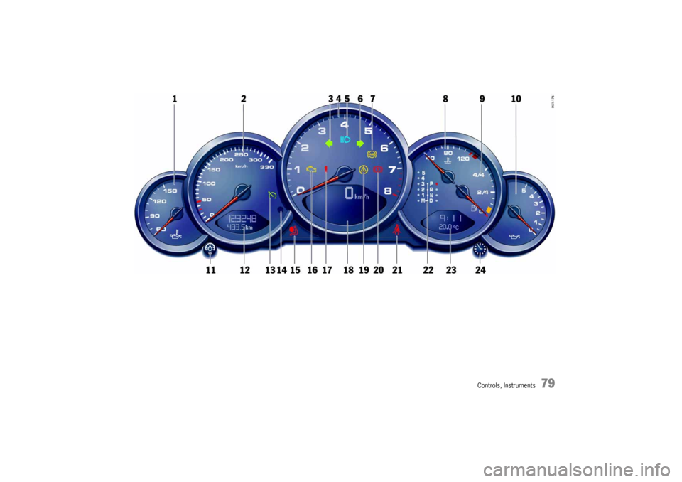
Instrument Panel Canada Models Also refer to the corresponding chapters in
the Owner’s Manual.
1. Engine oil temperature gauge
2. Speedometer with analogue display
3. Turn signal indicator light, left
4. Tachometer
5. High beam indicator light
6. Turn signal indicator light, right
7. ABS warning light
8. Cooling system
Temperature gauge, warning light
9. Fuel
Level gauge, warning light
10.Engine oil pressure gauge
11.Adjustment button for instrument illumination
and trip counter
12.Odometer and daily trip mileage display
13.Automatic speed control indicator light14.Light sensor for instrument illumination
15.Airbag warning light
16.Emission control warning light
(Check Engine)
17.Central warning light
18.On-board computer display
19.Porsche Stability Management
Multifunctional PSM light
20.Brake warning light
21.Safety belt warning light
22.Tiptronic indicator
23.Clock and outside temperature display
24 Adjustment button for clockWhen the ignition is switched on, the warning
lights light up for a lamp check.
Note
Warnings that have been given are stored in the
appropriate control unit memory and can be read
out at an authorized Porsche dealer.
This information can help to warn you about situa-
tions which may be hazardous to you or your car.
Page 79 of 282
Controls, Instruments
79
Page 80 of 282
80
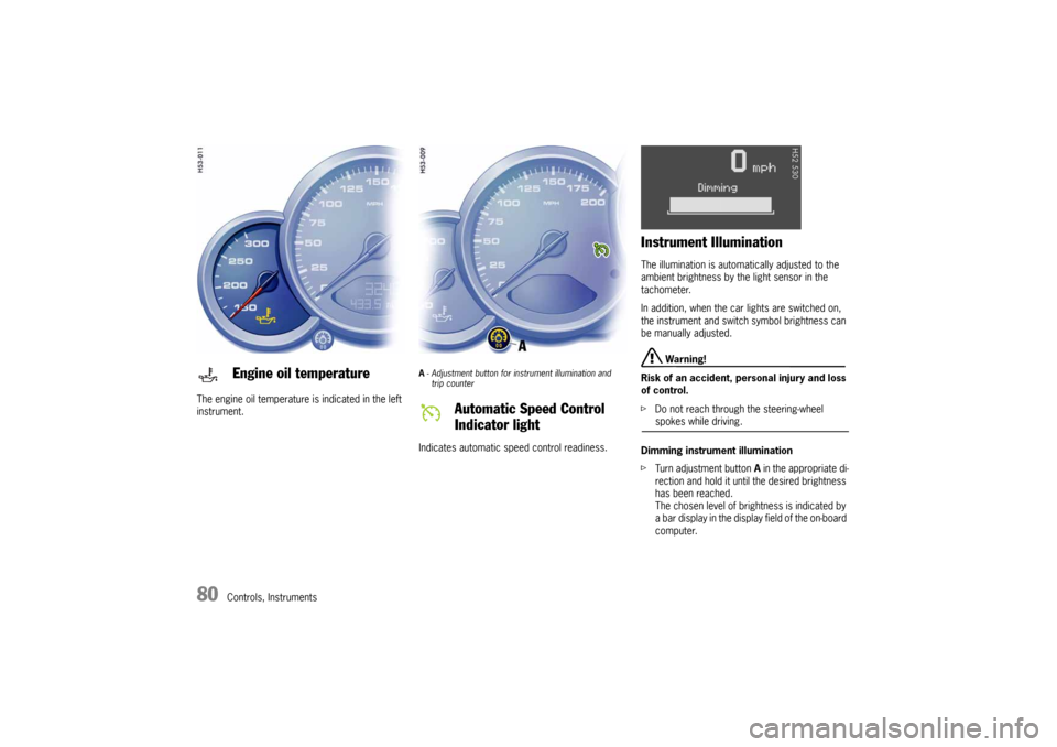
Controls, Instruments The engine oil temperature is indicated in the left
instrument.
A- Adjustment button for instrument illumination and
trip counter Indicates automatic speed control readiness.
Instrument Illumination The illumination is automatically adjusted to the
ambient brightness by the light sensor in the
tachometer.
In addition, when the car lights are switched on,
the instrument and switch symbol brightness can
be manually adjusted.
Warning!
Risk of an accident, personal injury and loss
of control.
fDo not reach through the steering-wheel spokes while driving.
Dimming instrument illumination
fTurn adjustment button A in the appropriate di-
rection and hold it until the desired brightness
has been reached.
The chosen level of brightness is indicated by
a bar display in the display field of the on-board
computer.
Engine oil temperature
Automatic Speed Control
Indicator light