lights Ram 1500 2013 Repair Manual
[x] Cancel search | Manufacturer: RAM, Model Year: 2013, Model line: 1500, Model: Ram 1500 2013Pages: 734, PDF Size: 5.47 MB
Page 555 of 734
CAUTION!
Connecting a trailer that is not compatible with the
ITBM system may result in reduced or complete loss
of trailer braking. There may be a increase in stop-
ping distance or trailer instability which could result
in damage to your vehicle, trailer, or other property.
WARNING!
Connecting a trailer that is not compatible with the
ITBM system may result in reduced or complete loss
of trailer braking. There may be a increase in stop-
ping distance or trailer instability which could result
in personal injury.NOTE:
•
An aftermarket controller may be available for use
with trailers with air or electric-over-hydraulic trailer
brake systems. To determine the type of brakes on
your trailer and the availability of controllers, check
with your trailer manufacturer or dealer.
• Removal of the ITBM will cause errors and it may
cause damage to the electrical system and electronic
modules of the vehicle. See your authorized dealer if
an aftermarket module is to be installed.
Towing Requirements – Trailer Lights And Wiring
Whenever you pull a trailer, regardless of the trailer size,
stoplights and turn signals on the trailer are required for
motoring safety.
5
STARTING AND OPERATING 553
Page 568 of 734
8. Release the brake pedal (and clutch pedal on manualtransmissions) for five seconds and ensure that there is
no vehicle movement.
9. Repeat steps 7 and 8 with automatic transmission in DRIVE or manual transmission in first gear.
10. Shift the transmission to NEUTRAL. Firmly apply the parking brake. Turn OFF the engine. For vehicles
with Keyless Enter-N-Go, press and hold the EN-
GINE START/STOP button until the engine shuts off.
11. Shift the transmission into PARK or place manual transmission in gear (NOT in Neutral). On 8-speed
transmissions the shifter will automatically select
PARK when the engine is turned off.
12. Turn the ignition switch to the OFF position, then cycle the key or the Keyless Enter-N-Go button to the
RUN position and back to the OFF position. Remove
the key fob from the ignition switch. 13. Attach the vehicle to the tow vehicle using a suitable
tow bar.
14. Release the parking brake.
NOTE: With electronic shift transfer case:
• Steps 2 through 4 are requirements that must be met
prior to pressing the NEUTRAL (N) button, and must
continue to be met until the shift has been completed.
If any of these requirements are not met prior to
pressing the NEUTRAL (N) button or are no longer
met during the shift, the NEUTRAL (N) indicator light
will flash continuously until all requirements are met
or until the NEUTRAL (N) button is released.
• The ignition switch must be in the ON/RUN position
for a shift to take place and for the position indicator
lights to be operable. If the ignition switch is not in the
ON/RUN position, the shift will not take place and no
position indicator lights will be on or flashing.
566 STARTING AND OPERATING
Page 570 of 734

5. Turn the engine OFF. Shift automatic transmission intoPARK. On 8-speed transmissions the shifter will auto-
matically select PARK when the engine is turned off.
6. Release the brake pedal (and clutch pedal on a manual transmission).
7. Disconnect vehicle from the tow vehicle.
8. Start the engine.
9. Press and hold the brake pedal.
10. Release the parking brake.
11. Shift the transmission into gear, release the brake pedal (and clutch pedal on manual transmissions),
and check that the vehicle operates normally. NOTE:
With electronic shift transfer case:
• Steps 3 and 4 are requirements that must be met prior
to pressing the button to shift out of NEUTRAL (N),
and must continue to be met until the shift has been
completed. If any of these requirements are not met
before pressing the button or are no longer met during
the shift, the NEUTRAL (N) indicator light will flash
continuously until all requirements are met or until the
button is released.
• The ignition switch must be in the ON/RUN position
for a shift to take place and for the position indicator
lights to be operable. If the ignition switch is not in the
ON/RUN position, the shift will not take place and no
position indicator lights will be on or flashing.
• A flashing NEUTRAL (N) position indicator light
indicates that shift requirements have not been met.
568 STARTING AND OPERATING
Page 667 of 734
Interior Care
Use MOPAR® Total Clean to clean fabric upholstery and
carpeting.
Use MOPAR® Total Clean to clean vinyl upholstery.
MOPAR® Total Clean is specifically recommended for
leather upholstery.
Your leather upholstery can be best preserved by regular
cleaning with a damp soft cloth. Small particles of dirt
can act as an abrasive and damage the leather upholstery
and should be removed promptly with a damp cloth.
Stubborn soils can be removed easily with a soft cloth
and MOPAR® Total Clean. Care should be taken to avoid
soaking your leather upholstery with any liquid. Please
do not use polishes, oils, cleaning fluids, solvents, deter-
gents, or ammonia-based cleaners to clean your leather
upholstery. Application of a leather conditioner is not
required to maintain the original condition.
WARNING!
Do not use volatile solvents for cleaning purposes.
Many are potentially flammable, and if used in
closed areas they may cause respiratory harm.
Cleaning Headlights
Your vehicle is equipped with plastic headlights and fog
lights (if equipped) that are lighter and less susceptible to
stone breakage than glass headlights.
Plastic is not as scratch resistant as glass and therefore
different lens cleaning procedures must be followed.
To minimize the possibility of scratching the lenses and
reducing light output, avoid wiping with a dry cloth. To
remove road dirt, wash with a mild soap solution fol-
lowed by rinsing.
Do not use abrasive cleaning components, solvents, steel
wool or other aggressive material to clean the lenses.
7
MAINTAINING YOUR VEHICLE 665
Page 672 of 734
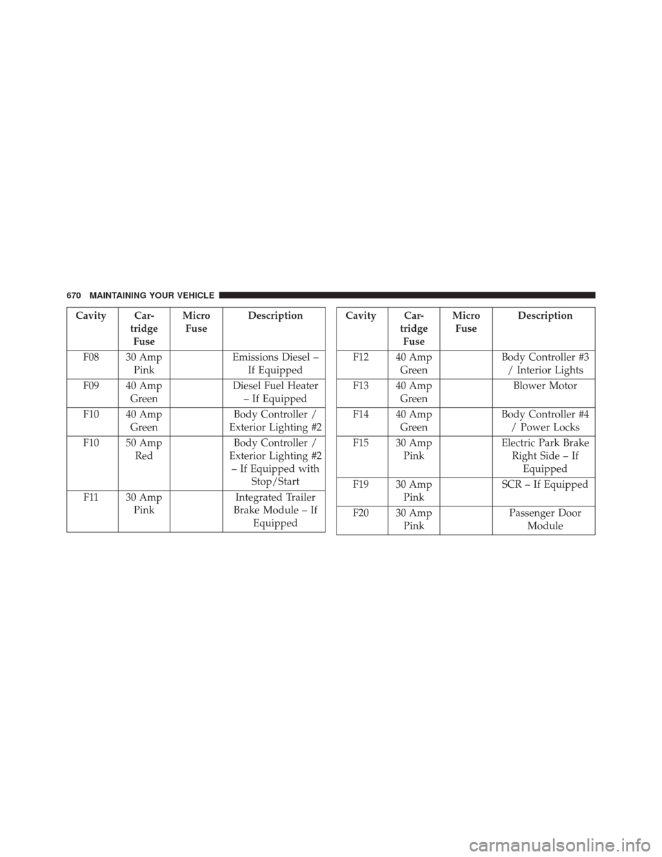
Cavity Car-tridgeFuse Micro
Fuse Description
F08 30 Amp Pink Emissions Diesel –
If Equipped
F09 40 Amp Green Diesel Fuel Heater
– If Equipped
F10 40 Amp Green Body Controller /
Exterior Lighting #2
F10 50 Amp Red Body Controller /
Exterior Lighting #2 – If Equipped with Stop/Start
F11 30 Amp Pink Integrated Trailer
Brake Module – If EquippedCavity Car- tridgeFuse Micro
Fuse Description
F12 40 Amp Green Body Controller #3
/ Interior Lights
F13 40 Amp Green Blower Motor
F14 40 Amp Green Body Controller #4
/ Power Locks
F15 30 Amp Pink Electric Park Brake
Right Side – If Equipped
F19 30 Amp Pink SCR – If Equipped
F20 30 Amp Pink Passenger Door
Module
670 MAINTAINING YOUR VEHICLE
Page 673 of 734
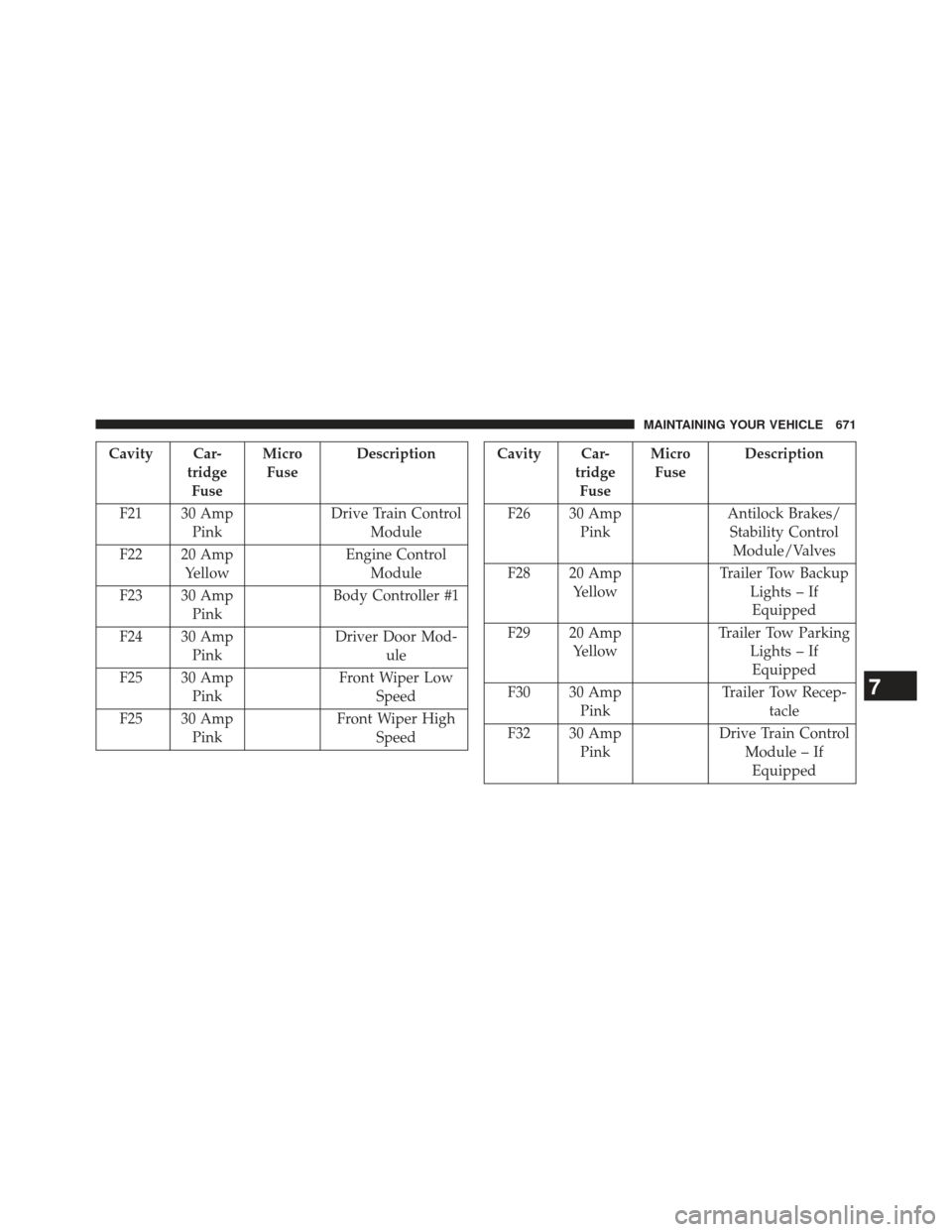
Cavity Car-tridgeFuse Micro
Fuse Description
F21 30 Amp Pink Drive Train Control
Module
F22 20 Amp Yellow Engine Control
Module
F23 30 Amp Pink Body Controller #1
F24 30 Amp Pink Driver Door Mod-
ule
F25 30 Amp Pink Front Wiper Low
Speed
F25 30 Amp Pink Front Wiper High
SpeedCavity Car- tridgeFuse Micro
Fuse Description
F26 30 Amp Pink Antilock Brakes/
Stability Control Module/Valves
F28 20 Amp Yellow Trailer Tow Backup
Lights – IfEquipped
F29 20 Amp Yellow Trailer Tow Parking
Lights – IfEquipped
F30 30 Amp Pink Trailer Tow Recep-
tacle
F32 30 Amp Pink Drive Train Control
Module – IfEquipped
7
MAINTAINING YOUR VEHICLE 671
Page 675 of 734
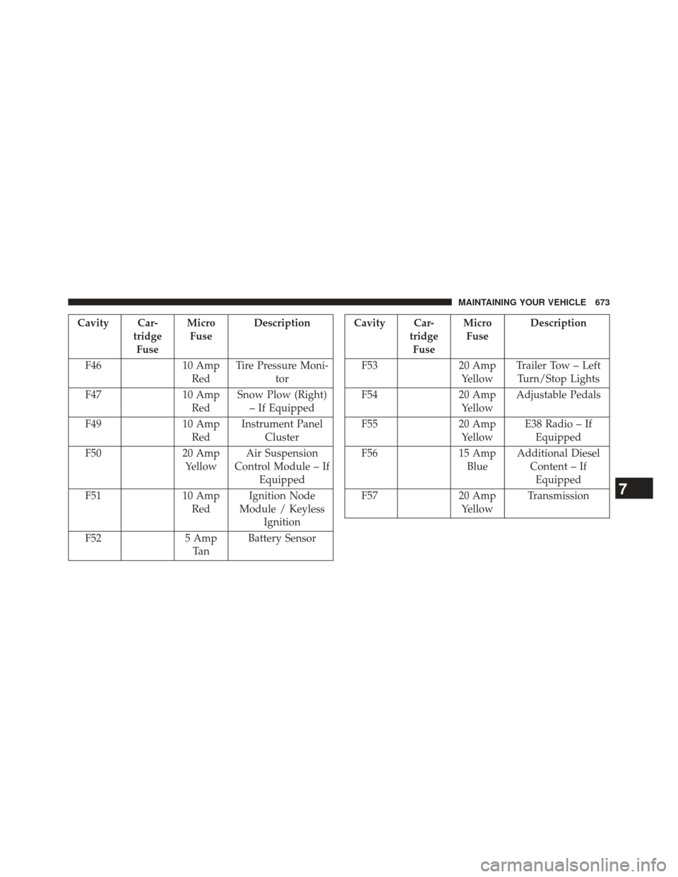
Cavity Car-tridgeFuse Micro
Fuse Description
F46 10 Amp
Red Tire Pressure Moni-
tor
F47 10 Amp
Red Snow Plow (Right)
– If Equipped
F49 10 Amp
Red Instrument Panel
Cluster
F50 20 Amp
Yellow Air Suspension
Control Module – If Equipped
F51 10 Amp
Red Ignition Node
Module / Keyless Ignition
F52 5 Amp
Ta n Battery SensorCavity Car-
tridgeFuse Micro
Fuse Description
F53 20 Amp
Yellow Trailer Tow – Left
Turn/Stop Lights
F54 20 Amp
Yellow Adjustable Pedals
F55 20 Amp
Yellow E38 Radio – If
Equipped
F56 15 Amp
Blue Additional Diesel
Content – IfEquipped
F57 20 Amp
Yellow Transmission
7
MAINTAINING YOUR VEHICLE 673
Page 678 of 734
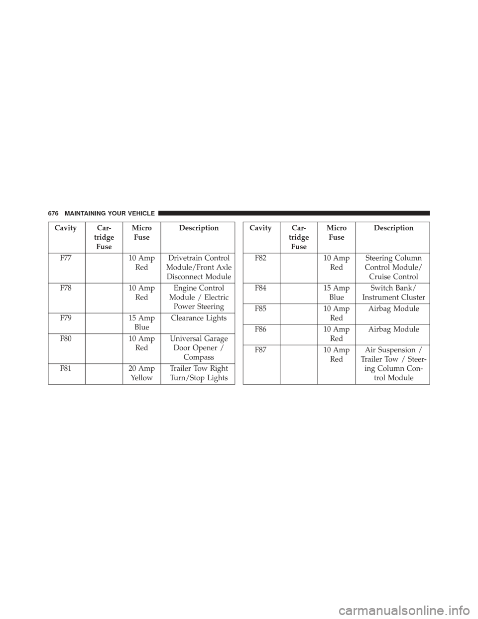
Cavity Car-tridgeFuse Micro
Fuse Description
F77 10 Amp
Red Drivetrain Control
Module/Front Axle Disconnect Module
F78 10 Amp
Red Engine Control
Module / Electric Power Steering
F79 15 Amp
Blue Clearance Lights
F80 10 Amp
Red Universal Garage
Door Opener / Compass
F81 20 Amp
Yellow Trailer Tow Right
Turn/Stop LightsCavity Car- tridgeFuse Micro
Fuse Description
F82 10 Amp
Red Steering Column
Control Module/ Cruise Control
F84 15 Amp
Blue Switch Bank/
Instrument Cluster
F85 10 Amp
Red Airbag Module
F86 10 Amp
Red Airbag Module
F87 10 Amp
Red Air Suspension /
Trailer Tow / Steer- ing Column Con- trol Module
676 MAINTAINING YOUR VEHICLE
Page 698 of 734
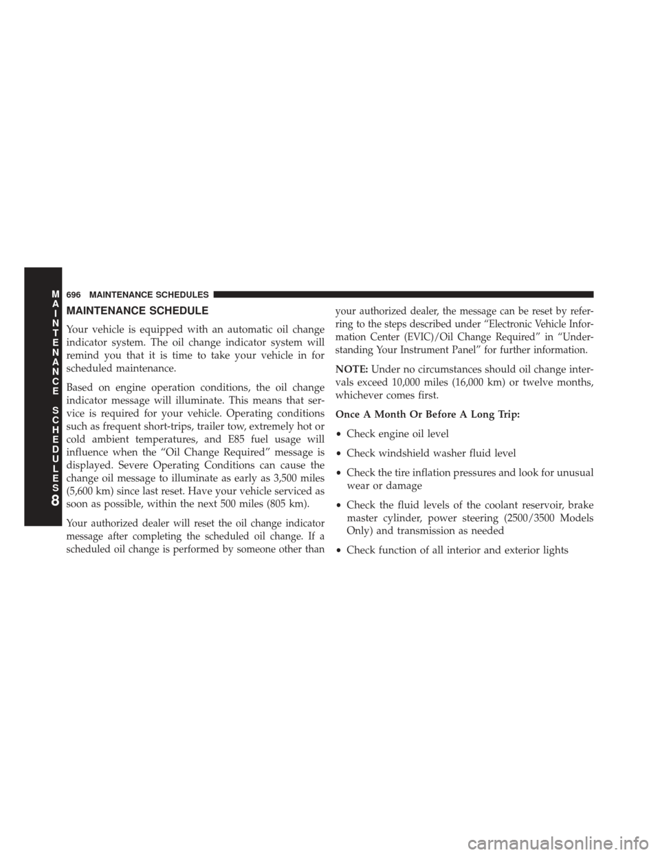
MAINTENANCE SCHEDULE
Your vehicle is equipped with an automatic oil change
indicator system. The oil change indicator system will
remind you that it is time to take your vehicle in for
scheduled maintenance.
Based on engine operation conditions, the oil change
indicator message will illuminate. This means that ser-
vice is required for your vehicle. Operating conditions
such as frequent short-trips, trailer tow, extremely hot or
cold ambient temperatures, and E85 fuel usage will
influence when the “Oil Change Required” message is
displayed. Severe Operating Conditions can cause the
change oil message to illuminate as early as 3,500 miles
(5,600 km) since last reset. Have your vehicle serviced as
soon as possible, within the next 500 miles (805 km).
Your authorized dealer will reset the oil change indicator
message after completing the scheduled oil change. If a
scheduled oil change is performed by someone other thanyour authorized dealer, the message can be reset by refer-
ring to the steps described under “Electronic Vehicle Infor-
mation Center (EVIC)/Oil Change Required” in “Under-
standing Your Instrument Panel” for further information.
NOTE:
Under no circumstances should oil change inter-
vals exceed 10,000 miles (16,000 km) or twelve months,
whichever comes first.
Once A Month Or Before A Long Trip:
• Check engine oil level
• Check windshield washer fluid level
• Check the tire inflation pressures and look for unusual
wear or damage
• Check the fluid levels of the coolant reservoir, brake
master cylinder, power steering (2500/3500 Models
Only) and transmission as needed
• Check function of all interior and exterior lights
8
M
A I
N T
E
N
A
N
C E
S
C
H E
D
U L
E
S696 MAINTENANCE SCHEDULES
Page 716 of 734
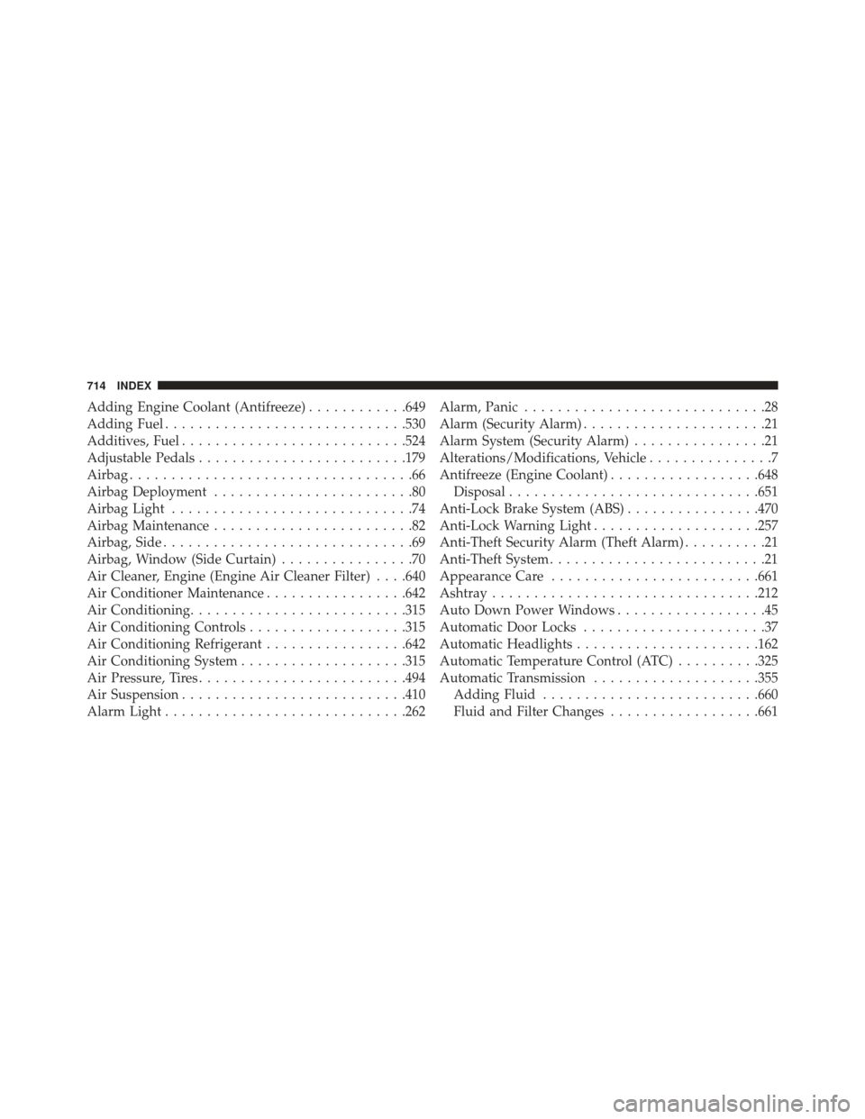
Adding Engine Coolant (Antifreeze)............649
Adding Fuel ............................ .530
Additives, Fuel .......................... .524
Adjustable Pedals ........................ .179
Airbag ..................................66
Airbag Deployment ........................80
Airbag Light .............................74
Airbag Maintenance ........................82
Airbag, Side ..............................69
Airbag, Window (Side Curtain) ................70
Air Cleaner, Engine (Engine Air Cleaner Filter) . . . .640
Air Conditioner Maintenance .................642
Air Conditioning ......................... .315
Air Conditioning Controls ...................315
Air Conditioning Refrigerant .................642
Air Conditioning System ....................315
Air Pressure, Tires ........................ .494
Air Suspension .......................... .410
Alarm Light ............................ .262Alarm, Panic
.............................28
Alarm (Security Alarm) ......................21
Alarm System (Security Alarm) ................21
Alterations/Modifications, Vehicle ...............7
Antifreeze (Engine Coolant) ..................648
Disposal ............................. .651
Anti-Lock Brake System (ABS) ................470
Anti-Lock Warning Light ....................257
Anti-Theft Security Alarm (Theft Alarm) ..........21
Anti-Theft System ..........................21
Appearance Care ........................ .661
Ashtray ............................... .212
Auto Down Power Windows ..................45
Automatic Door Locks ......................37
Automatic Headlights ..................... .162
Automatic Temperature Control (ATC) ..........325
Automatic Transmission ....................355
Adding Fluid ......................... .660
Fluid and Filter Changes ..................661
714 INDEX