PIN Ram 1500 2016 Repair Manual
[x] Cancel search | Manufacturer: RAM, Model Year: 2016, Model line: 1500, Model: Ram 1500 2016Pages: 916, PDF Size: 7.55 MB
Page 612 of 916
NOTE: How to spool under no load:Arrange the re-
mote control lead so it cannot be caught in the winch.
Arrange the wire rope so it will not kink or tangle when
spooled. Be sure any wire rope already on the spooling
drum is wound tightly and evenly layered. Tighten and
straighten the layer if necessary. Keep the wire rope
under light tension and spool the wire rope back and
onto the winch drum in even layers. Stop frequently to
tighten and straighten the layers as necessary. Repeat this
process until the winch hook is the same distance as the
full length of the remote control from the winch. Pinch
the hook between your thumb and forefinger and attach
the hook strap. Hold the hook strap between the thumb
and forefinger to keep tension on the wire rope. Walk the
wire rope towards the fairlead, carefully spooling in the
remaining wire rope. By pulsing the remote control
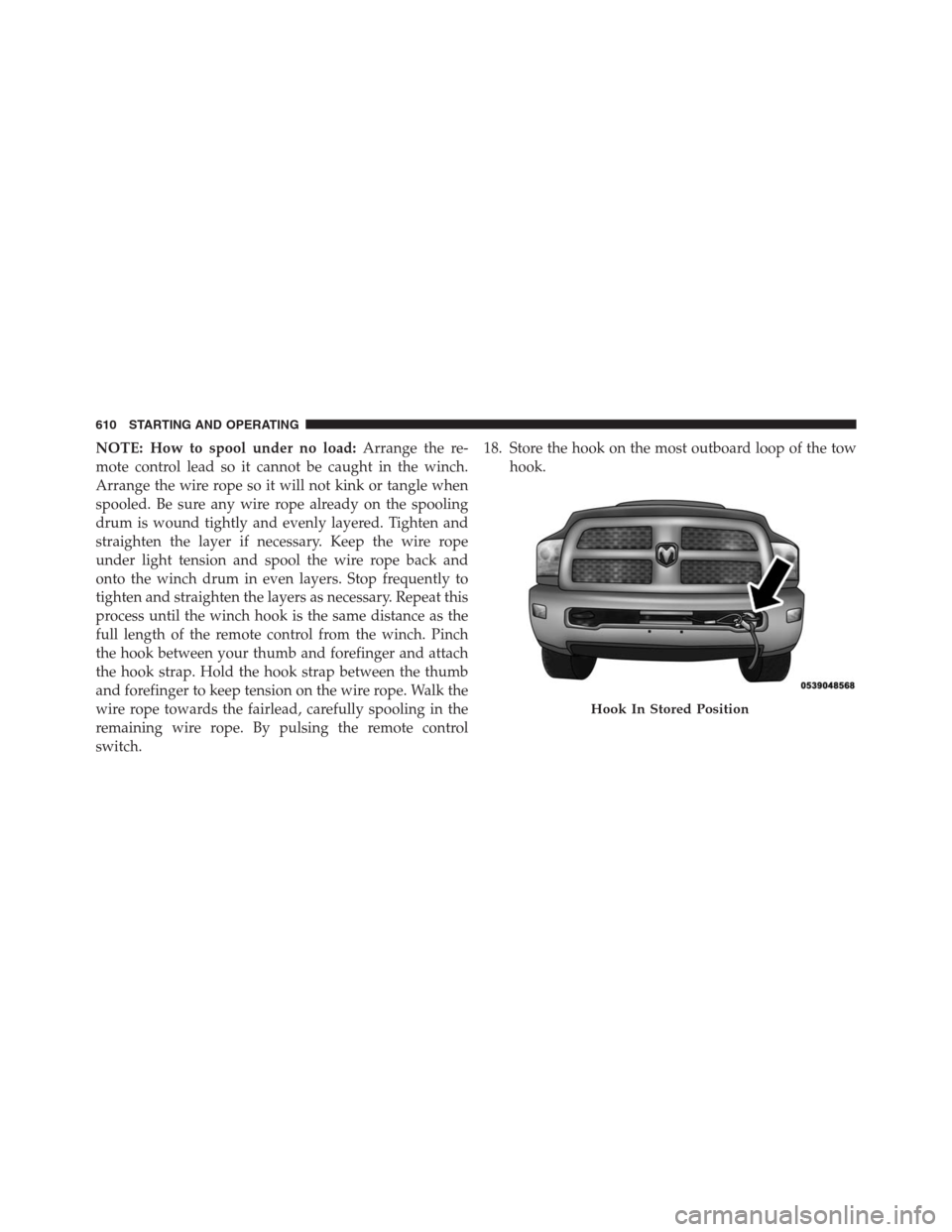
switch.18. Store the hook on the most outboard loop of the tow
hook.
Hook In Stored Position
610 STARTING AND OPERATING
Page 623 of 916
WARNING!(Continued)
can cause possible loss of anti-lock braking capa-
bility. Installation of such equipment should be
performed by qualified professionals.
•Pumping of the Anti-Lock Brakes will diminish
their effectiveness and may lead to a collision.
Pumping makes the stopping distance longer. Just
press firmly on your brake pedal when you need to
slow down or stop.
•The ABS cannot prevent the natural laws of phys-
ics from acting on the vehicle, nor can it increase
braking or steering efficiency beyond that afforded
by the condition of the vehicle brakes and tires or
the traction afforded.
•The ABS cannot prevent collisions, including those
resulting from excessive speed in turns, following
another vehicle too closely, or hydroplaning.
(Continued)
WARNING!(Continued)
•The capabilities of an ABS equipped vehicle must
never be exploited in a reckless or dangerous
manner that could jeopardize the user ’s safety or
the safety of others.
ABS is designed to function with the OEM tires. Modifi-
cation may result in degraded ABS performance.
Anti-Lock Brake Warning Light
The amber “Anti-Lock Brake Warning Light” will turn on
when the ignition switch is turned to the ON position
and may stay on for as long as four seconds.
If the “Anti-Lock Brake Warning Light” remains on or
comes on while driving, it indicates that the anti-lock
portion of the brake system is not functioning and that
service is required. However, the conventional brake
system will continue to operate normally if the “Brake
System Warning Light” is not on.
5
STARTING AND OPERATING 621
Page 624 of 916
If the “Anti-Lock Brake Warning Light” is on, the brake
system should be serviced as soon as possible to restore
the benefits of anti-lock brakes. If the “Anti-Lock Brake
Warning Light” does not come on when the ignition
switch is turned to the ON position, have the light
repaired as soon as possible.
Brake Assist System (BAS)
The BAS is designed to optimize the vehicle’s braking
capability during emergency braking maneuvers. The
system detects an emergency braking situation by sens-
ing the rate and amount of brake application and then
applies optimum pressure to the brakes. This can help
reduce braking distances. The BAS complements the
anti-lock brake system (ABS). Applying the brakes very
quickly results in the best BAS assistance. To receive the
benefit of the system, you must apply continuous brak-
ing pressure during the stopping sequence, (do not
“pump” the brakes). Do not reduce brake pedal pressureunless braking is no longer desired. Once the brake pedal
is released, the BAS is deactivated.
WARNING!
The Brake Assist System (BAS) cannot prevent the
natural laws of physics from acting on the vehicle,
nor can it increase the traction afforded by prevailing
road conditions. BAS cannot prevent collisions, in-
cluding those resulting from excessive speed in
turns, driving on very slippery surfaces, or hydro-
planing. The capabilities of a BAS-equipped vehicle
must never be exploited in a reckless or dangerous
manner, which could jeopardize the user’s safety or
the safety of others.
Hill Start Assist (HSA)
The HSA system is designed to mitigate roll back from a
complete stop while on an incline. If the driver releases
622 STARTING AND OPERATING
Page 627 of 916
Center (EVIC)” or “Driver Information Display (DID)”
in “Understanding Your Instrument Panel” for further
information.
•If disabling HSA using Uconnect Settings, refer to
“Uconnect Settings” in “Understanding Your Instru-
ment Panel” for further information.
For vehicles not equipped with the EVIC/DID, perform
the following steps:
1. Center the steering wheel (front wheels pointing
straight forward).
2. Shift the transmission into PARK.
3. Apply the parking brake.
4. Start the engine.
5. Rotate the steering wheel slightly more than one-half
turn to the left.6. Push the “ESC Off” button located in the lower switch
bank below the climate control four times within
twenty seconds. The “ESC Off Indicator Light” should
turn on and turn off two times.
7. Rotate the steering wheel back to center and then an
additional slighty more than one-half turn to the right.
8. Turn the ignition switch to the OFF position and then
back to the ON position. If the sequence was com-
pleted properly, the “ESC Off Indicator Light” will
blink several times to confirm HSA is disabled.
9. Repeat these steps if you want to return this feature to
its previous setting.
Traction Control System (TCS)
This system monitors the amount of wheel spin of each of
the driven wheels. If wheel spin is detected, the TCS may
apply brake pressure to the spinning wheel(s) and/or
reduce engine power to provide enhanced acceleration
5
STARTING AND OPERATING 625
Page 628 of 916
and stability. A feature of the TCS, Brake Limited Differ-
ential (BLD), functions similar to a limited slip differen-
tial and controls the wheel spin across a driven axle. If
one wheel on a driven axle is spinning faster than the
other, the system will apply the brake of the spinning
wheel. This will allow more engine torque to be applied
to the wheel that is not spinning. BLD may remain
enabled even if TCS and ESC are in a reduced mode.
Electronic Stability Control (ESC)
This system enhances directional control and stability of
the vehicle under various driving conditions. ESC cor-
rects for oversteering or understeering of the vehicle by
applying the brake of the appropriate wheel(s) to assist in
counteracting the oversteer or understeer condition. En-
gine power may also be reduced to help the vehicle
maintain the desired path.
ESC uses sensors in the vehicle to determine the vehicle
path intended by the driver and compares it to the actualpath of the vehicle. When the actual path does not match
the intended path, ESC applies the brake of the appro-
priate wheel to assist in counteracting the oversteer or
understeer condition.
•Oversteer - when the vehicle is turning more than
appropriate for the steering wheel position.
•Understeer - when the vehicle is turning less than
appropriate for the steering wheel position.
The “ESC Activation/Malfunction Indicator Light” lo-
cated in the instrument cluster will start to flash as soon
as the ESC system becomes active. The “ESC Activation/
Malfunction Indicator Light” also flashes when the TCS
is active. If the “ESC Activation/Malfunction Indicator
Light” begins to flash during acceleration, ease up on the
accelerator and apply as little throttle as possible. Be sure
to adapt your speed and driving to the prevailing road
conditions.
626 STARTING AND OPERATING
Page 630 of 916
ESC Operating Modes
NOTE:Depending upon model and mode of operation,
the ESC system may have multiple operating modes.
ESC On
This is the normal operating mode for the ESC. When-
ever the vehicle is started, the ESC system will be in this
mode. This mode should be used for most driving
conditions. Alternate ESC modes should only be used for
specific reasons as noted in the following paragraphs.
Partial Off
The “Partial Off” mode is intended for times when a
more spirited driving experience is desired. This mode
may modify TCS and ESC thresholds for activation,
which allows for more wheel spin than normally al-
lowed. This mode may be useful if the vehicle becomes
stuck.To enter the “Partial Off” mode, momentarily push the
“ESC Off” switch and the “ESC Off Indicator Light” will
illuminate. To turn the ESC on again, momentarily push
the “ESC Off” switch and the “ESC Off Indicator Light”
will turn off.
NOTE:For vehicles with multiple partial ESC modes a
momentary button push will toggle the ESC mode.
Multiple momentary button pushed may be required to
return to ESC On.
NOTE:
•When in “Partial Off” mode, the TCS functionality of
ESC, (except for the limited slip feature described in
the TCS section), has been disabled and the “ESC Off
Indicator Light” will be illuminated. When in “Partial
Off” mode, the engine power reduction feature of TCS
is disabled, and the enhanced vehicle stability offered
by the ESC system is reduced.
628 STARTING AND OPERATING
Page 649 of 916
WARNING!
Overloading of your tires is dangerous. Overloading
can cause tire failure, affect vehicle handling, and
increase your stopping distance. Use tires of the
recommended load capacity for your vehicle. Never
overload them.
TIRES — GENERAL INFORMATION
Tire Pressure
Proper tire inflation pressure is essential to the safe and
satisfactory operation of your vehicle. Four primary areas
are affected by improper tire pressure:
•Safety and Vehicle Stability
•Economy
•Tread Wear
•Ride Comfort
Safety
WARNING!
•Improperly inflated tires are dangerous and can
cause collisions.
•Underinflation increases tire flexing and can result
in overheating and tire failure.
•Overinflation reduces a tire’s ability to cushion
shock. Objects on the road and chuckholes can
cause damage that result in tire failure.
•Overinflated or underinflated tires can affect ve-
hicle handling and can fail suddenly, resulting in
loss of vehicle control.
•Unequal tire pressures can cause steering prob-
lems. You could lose control of your vehicle.
(Continued)
5
STARTING AND OPERATING 647
Page 658 of 916
Tire Spinning
When stuck in mud, sand, snow, or ice conditions, do not
spin your vehicle’s wheels above 30 mph (48 km/h) or
for longer than 30 seconds continuously without stop-
ping.
Refer to “Freeing A Stuck Vehicle” in “What To Do In
Emergencies” for further information.
WARNING!
Fast spinning tires can be dangerous. Forces gener-
ated by excessive wheel speeds may cause tire dam-
age or failure. A tire could explode and injure some-
one. Do not spin your vehicle’s wheels faster than
30 mph (48 km/h) for more than 30 seconds continu-
ously when you are stuck, and do not let anyone near
a spinning wheel, no matter what the speed.
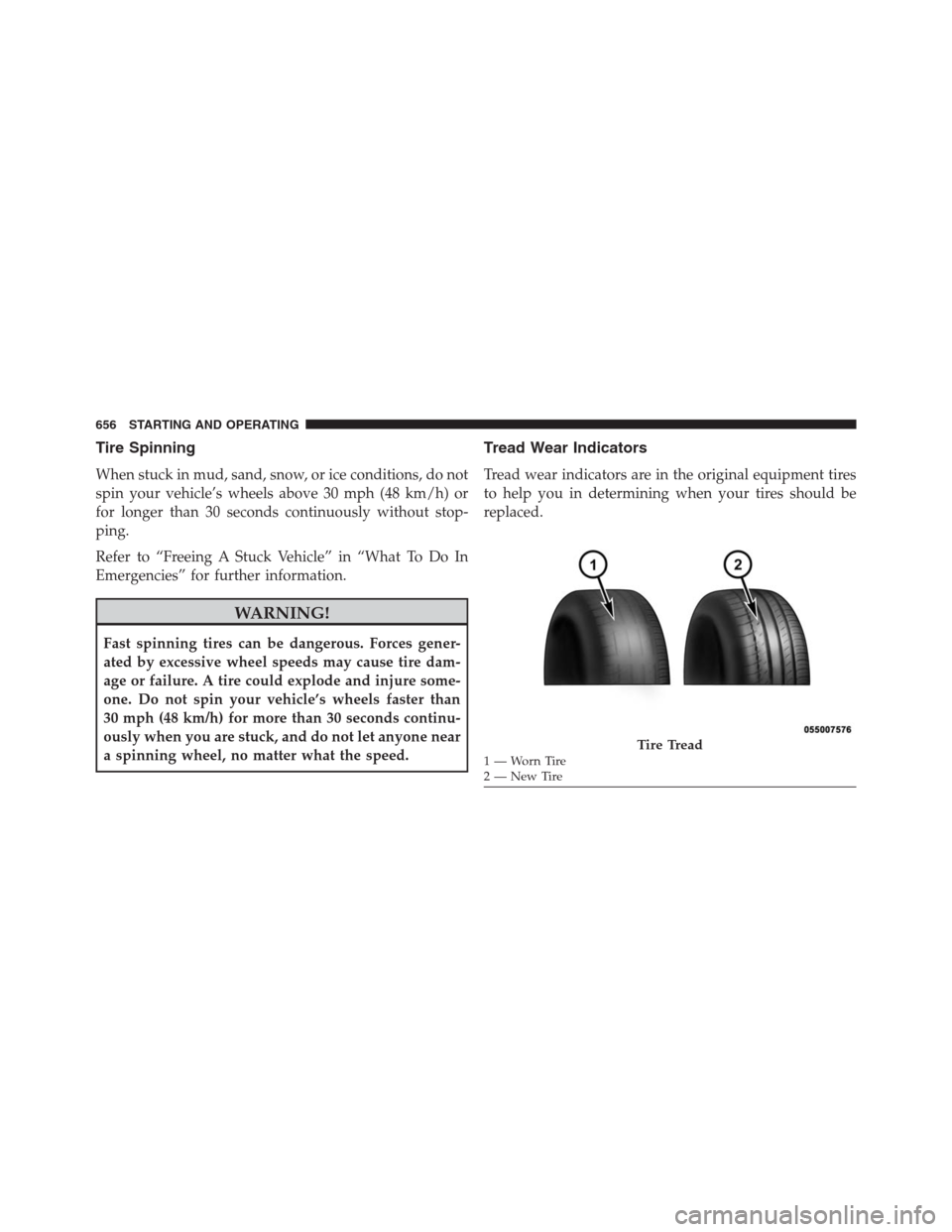
Tread Wear Indicators
Tread wear indicators are in the original equipment tires
to help you in determining when your tires should be
replaced.
Tire Tread1—WornTire
2—NewTire 656 STARTING AND OPERATING
Page 669 of 916
CAUTION!(Continued)
moisture and dirt from entering the valve stem,
which could damage the TPMS sensor.
NOTE:
•The TPMS is not intended to replace normal tire care
and maintenance or to provide warning of a tire failure
or condition.
•The TPMS should not be used as a tire pressure gauge
while adjusting your tire pressure.
•Driving on a significantly under-inflated tire causes
the tire to overheat and can lead to tire failure.
Under-inflation also reduces fuel efficiency and tire
tread life, and may affect the vehicle’s handling and
stopping ability.
•The TPMS is not a substitute for proper tire mainte-
nance, and it is the driver ’s responsibility to maintaincorrect tire pressure using an accurate tire pressure
gauge, even if under-inflation has not reached the level
to trigger illumination of the “Tire Pressure Monitor-
ing Telltale Light.”
•Seasonal temperature changes will affect tire pressure,
and the TPMS will monitor the actual tire pressure in
the tire.
Premium System
The Tire Pressure Monitor System (TPMS) uses wireless
technology with wheel rim mounted electronic sensors to
monitor tire pressure levels. Sensors mounted to each
wheel as part of the valve stem transmit tire pressure
readings to the receiver module.
NOTE:It is particularly important for you to check the
tire pressure in all of the tires on your vehicle monthly
and to maintain the proper pressure.
5
STARTING AND OPERATING 667
Page 692 of 916
WARNING!
It is important that you do not exceed the maximum
front or rear GAWR. A dangerous driving condition
can result if either rating is exceeded. You could lose
control of the vehicle and have an accident.
Tongue Weight (TW)
The tongue weight is the downward force exerted on the
hitch ball by the trailer. The recommended tongue weight
is 10% to 15% of the vehicle’s GTW for a conventional
hitch. You must consider this as part of the load on your
vehicle.
Frontal Area
The frontal area is the maximum height multiplied by the
maximum width of the front of a trailer.
Trailer Sway Control
The trailer sway control can be a mechanical telescoping
link that can be installed between the hitch receiver and
the trailer tongue that typically provides adjustable fric-
tion associated with the telescoping motion to dampen
any unwanted trailer swaying motions while traveling.
If equipped, the electronic Trailer Sway Control (TSC)
recognizes a swaying trailer and automatically applies
individual wheel brakes and/or reduces engine power to
attempt to eliminate the trailer sway.
Weight-Carrying Hitch
A weight-carrying hitch supports the trailer tongue
weight, just as if it were luggage located at a hitch ball or
some other connecting point of the vehicle. These kinds
of hitches are the most popular on the market today and
they are commonly used to tow small and medium sized
trailers.
690 STARTING AND OPERATING