PIN Ram 1500 2016 Manual PDF
[x] Cancel search | Manufacturer: RAM, Model Year: 2016, Model line: 1500, Model: Ram 1500 2016Pages: 916, PDF Size: 7.55 MB
Page 698 of 916

Fifth-Wheel Hitch
The fifth-wheel hitch is a special high platform with a
coupling that mounts over the rear axle of the tow vehicle
in the truck bed. It connects a vehicle and fifth-wheel
trailer with a coupling king pin.
Gooseneck Hitch
The gooseneck hitch employs a pivoted coupling arm
which attaches to a ball mounted in the bed of a pickup
truck. The coupling arm connects to the hitch mounted
over the rear axle in the truck bed.
Trailer Hitch Type and Maximum Trailer Weight
The following chart provides the maximum trailer
weight a given factory equipped trailer hitch type can
tow and should be used to assist you in selecting the
correct trailer hitch for your intended towing condition.
Trailer Hitch Type and Maximum Trailer Weight
Hitch Type Max. Trailer Weight / Max.
Tongue Weight
Class III Bumper
Hitch - 1500 Model5,000 lbs (2,268 kg) / 500 lbs
(226 kg)
Class IV - 1500
Model11,000 lbs (4,989 kg) / 1100
lbs (498 kg)
Class V - 2500/3500
Models18,000 lbs (8,164 kg) /
1800 lbs (816 kg)
Fifth Wheel - 2500
Model25,000 lbs (11,339 kg) /
5000 lbs (2,267 kg)
Gooseneck - 2500
Model20,000 lbs (9,071 kg) /
4000 lbs (1,814 kg)
696 STARTING AND OPERATING
Page 703 of 916

Towing Requirements — Trailer Brakes
WARNING!
•Do not connect trailer brakes to your vehicle’s
hydraulic brake lines. It can overload your brake
system and cause it to fail. You might not have
brakes when you need them and could have an
accident.
•Towing any trailer will increase your stopping
distance. When towing you should allow for addi-
tional space between your vehicle and the vehicle
in front of you. Failure to do so could result in an
accident.
CAUTION!
If the trailer weighs more than 1,000 lbs (454 kg)
loaded, it should have its own brakes and they
should be of adequate capacity. Failure to do this
could lead to accelerated brake lining wear, higher
brake pedal effort, and longer stopping distances.
•Donotinterconnect the hydraulic brake system or
vacuum system of your vehicle with that of the trailer.
This could cause inadequate braking and possible
personal injury.
•An electronically actuated trailer brake controller is
required when towing a trailer with electronically
actuated brakes. When towing a trailer equipped with
a hydraulic surge actuated brake system, an electronic
brake controller is not required.
5
STARTING AND OPERATING 701
Page 708 of 916
CAUTION!
Connecting a trailer that is not compatible with the
ITBM system may result in reduced or complete loss
of trailer braking. There may be a increase in stop-
ping distance or trailer instability which could result
in damage to your vehicle, trailer, or other property.
WARNING!
Connecting a trailer that is not compatible with the
ITBM system may result in reduced or complete loss
of trailer braking. There may be a increase in stop-
ping distance or trailer instability which could result
in personal injury.NOTE:
•An aftermarket controller may be available for use
with trailers with air or electric-over-hydraulic trailer
brake systems. To determine the type of brakes on
your trailer and the availability of controllers, check
with your trailer manufacturer or dealer.
•Removal of the ITBM will cause errors and it may
cause damage to the electrical system and electronic
modules of the vehicle. See your authorized dealer if
an aftermarket module is to be installed.
706 STARTING AND OPERATING
Page 709 of 916
Towing Requirements — Trailer Lights And Wiring
Whenever you pull a trailer, regardless of the trailer size,
stoplights and turn signals on the trailer are required for
motoring safety.
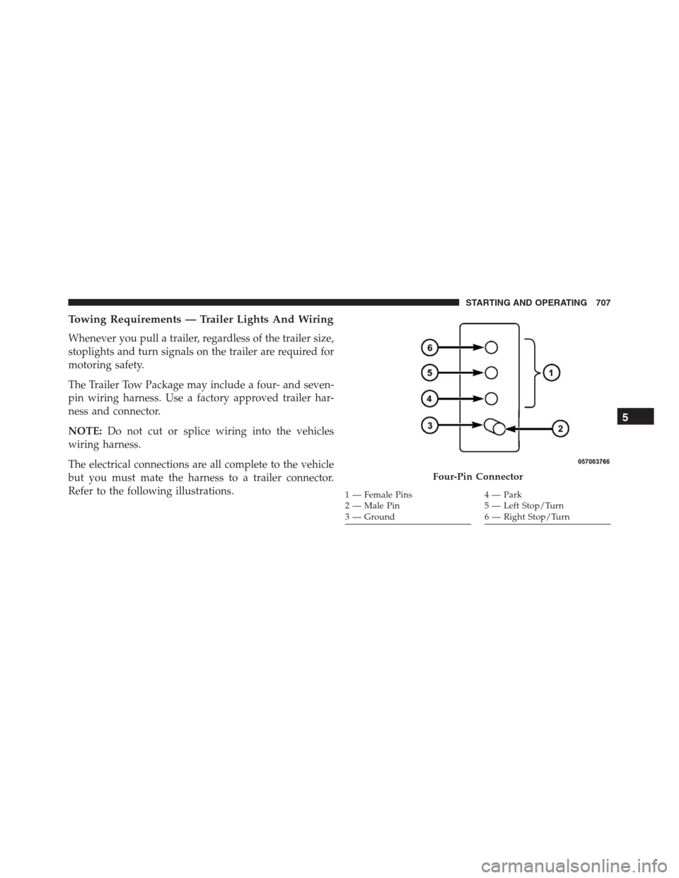
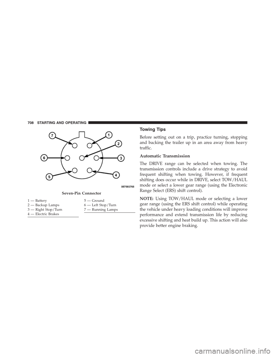
The Trailer Tow Package may include a four- and seven-
pin wiring harness. Use a factory approved trailer har-
ness and connector.
NOTE:Do not cut or splice wiring into the vehicles
wiring harness.
The electrical connections are all complete to the vehicle
but you must mate the harness to a trailer connector.
Refer to the following illustrations.
Four-Pin Connector
1 — Female Pins
2 — Male Pin
3 — Ground4 — Park
5 — Left Stop/Turn
6 — Right Stop/Turn
5
STARTING AND OPERATING 707
Page 710 of 916
Towing Tips
Before setting out on a trip, practice turning, stopping
and backing the trailer up in an area away from heavy
traffic.
Automatic Transmission
The DRIVE range can be selected when towing. The
transmission controls include a drive strategy to avoid
frequent shifting when towing. However, if frequent
shifting does occur while in DRIVE, select TOW/HAUL
mode or select a lower gear range (using the Electronic
Range Select (ERS) shift control).
NOTE:Using TOW/HAUL mode or selecting a lower
gear range (using the ERS shift control) while operating
the vehicle under heavy loading conditions will improve
performance and extend transmission life by reducing
excessive shifting and heat build up. This action will also
provide better engine braking.
Seven-Pin Connector
1 — Battery
2 — Backup Lamps
3 — Right Stop/Turn
4 — Electric Brakes5 — Ground
6 — Left Stop/Turn
7 — Running Lamps 708 STARTING AND OPERATING
Page 715 of 916
Maintain and operate your vehicle and snowplow equip-
ment following the recommendations provided by the
specific snowplow manufacturer.
Over The Road Operation With Snowplow
Attached
The blade restricts air flow to the radiator and causes the
engine to operate at higher than normal temperatures.
Therefore, when transporting the plow, angle the blade
completely and position it as low as road or surface
conditions permit. Do not exceed 40 mph (64 km/h). The
operator should always maintain a safe stopping distance
and allow adequate passing clearance.
Operating Tips
Under ideal snow plowing conditions, 20 mph (32 km/h)
should be maximum operating speed. The operator
should be familiar with the area and surface to be
cleaned. Reduce speed and use extreme caution when
plowing unfamiliar areas or under poor visibility.
General Maintenance
Snowplows should be maintained in accordance with the
plow manufacturer’s instructions.
Keep all snowplow electrical connections and battery
terminals clean and free of corrosion.
When plowing snow, to avoid transmission and drivetrain
damage, the following precautions should be observed.
•Operate with transfer case in 4L when plowing small or
congested areas where speeds are not likely to exceed
15 mph (24 km/h). At higher speeds operate in 4H.
•Vehicles with automatic transmissions should use 4L
range when plowing deep or heavy snow for extended
periods of time to avoid transmission overheating.
•Do not shift the transmission unless the engine has
returned to idle and wheels have stopped. Make a
practice of stepping on the brake pedal while shifting
the transmission.
5
STARTING AND OPERATING 713
Page 717 of 916
NOTE:
•When recreational towing your vehicle, always follow
applicable state and provincial laws. Contact state and
provincial Highway Safety offices for additional de-
tails.
•Vehicles equipped with air suspension must be placed
in Transport mode before tying them down (from the
body) on a trailer or flatbed truck. Refer to “Air
Suspension – If Equipped” for more information. If the
vehicle cannot be placed in Transport mode (for ex-
ample, engine will not run), tie-downs must be fas-
tened to the axles (not to the body). Failure to follow
these instructions may cause fault codes to be set
and/or cause loss of proper tie-down tension.
Recreational Towing — Two-Wheel Drive Models
DO NOT flat tow this vehicle. Damage to the drivetrain
will result.Recreational towing (for two-wheel drive models) is
allowedONLYif the rear wheels areOFFthe ground.
This may be accomplished using a tow dolly or vehicle
trailer. If using a tow dolly, follow this procedure:
1. Properly secure the dolly to the tow vehicle, following
the dolly manufacturer’s instructions.
2. Drive the rear wheels onto the tow dolly.
3. Firmly apply the parking brake. Place automatic trans-
mission in PARK, manual transmission in gear (not in
NEUTRAL).
4. Properly secure the rear wheels to the dolly, following
the dolly manufacturer’s instructions.
5. Turn the ignition switch to the OFF position and
remove the Key Fob.
6. Install a suitable clamping device, designed for tow-
ing, to secure the front wheels in the straight position.
5
STARTING AND OPERATING 715
Page 735 of 916

Assembled For Jack OperationWARNING!
After using the jack and tools, always reinstall them
in the original carrier and location. While driving
you may experience abrupt stopping, rapid accelera-
tion or sharp turns. A loose jack, tools, bracket or
other objects in the vehicle may move around with
force, resulting in serious injury.
Assembled For Jack Operation
1 — Extension With Jack Hook 4 — Extension 4
2 — Extension 2 5 — Wheel Wrench
3 — Extension 3
6
WHAT TO DO IN EMERGENCIES 733
Page 751 of 916

WARNING!(Continued)
you may experience abrupt stopping, rapid accelera-
tion or sharp turns. A loose jack, tools, bracket or
other objects in the vehicle may move around with
force, resulting in serious injury.
Jacking And Tire Changing 2500 And 3500 Series
Trucks
WARNING!
•Do not attempt to change a tire on the side of the
vehicle close to moving traffic. Pull far enough off
the road to avoid the danger of being hit when
operating the jack or changing the wheel.
•Being under a jacked-up vehicle is dangerous. The
vehicle could slip off the jack and fall on you. You
(Continued)
WARNING!(Continued)
could be crushed. Never put any part of your body
under a vehicle that is on a jack. If you need to get
under a raised vehicle, take it to a service center
where it can be raised on a lift.
•Never start or run the engine while the vehicle is
on a jack.
•The jack is designed to be used as a tool for
changing tires only. The jack should not be used to
lift the vehicle for service purposes. The vehicle
should be jacked on a firm level surface only.
Avoid ice or slippery areas.
Jack Location
The jack and jack tools are stored under the front
passenger seat.
6
WHAT TO DO IN EMERGENCIES 749
Page 755 of 916

Assembled For Jack OperationWARNING!
After using the jack and tools, always reinstall them
in the original carrier and location. While driving
you may experience abrupt stopping, rapid accelera-
tion or sharp turns. A loose jack, tools, bracket or
other objects in the vehicle may move around with
force, resulting in serious injury.
Removing The Spare Tire
1. Remove the spare tire before attempting to jack up the
truck. Attach the wheel wrench to the jack extension
tube with the curved angle facing away from the
vehicle. Insert the tube through the access hole be-
tween the lower tailgate and the top of the bumper
and into the winch mechanism tube.
Assembled For Jack Operation
1 — Extension With Jack Hook 4 — Extension 4
2 — Extension 2 5 — Wheel Wrench
3 — Extension 3
6
WHAT TO DO IN EMERGENCIES 753