AIR Ram 1500 2017 Owner's Manual
[x] Cancel search | Manufacturer: RAM, Model Year: 2017, Model line: 1500, Model: Ram 1500 2017Pages: 734, PDF Size: 7.3 MB
Page 567 of 734
Display Messages
The trailer brake control interacts with the instrument
cluster display. Display messages, along with a single
chime, will be displayed when a malfunction is determined
in the trailer connection, trailer brake control, or on the
trailer. Refer to “Instrument Cluster Display” in “Under-
standing Your Instrument Panel” for further information.
CAUTION!
Connecting a trailer that is not compatible with the
ITBM system may result in reduced or complete loss of
trailer braking. There may be a increase in stopping
distance or trailer instability which could result in
damage to your vehicle, trailer, or other property.
WARNING!
Connecting a trailer that is not compatible with the
ITBM system may result in reduced or complete loss of
trailer braking. There may be a increase in stopping
distance or trailer instability which could result in
personal injury.NOTE:
•
An aftermarket controller may be available for use with
trailers with air or electric-over-hydraulic trailer brake
systems. To determine the type of brakes on your trailer
and the availability of controllers, check with your
trailer manufacturer or dealer.
• Removal of the ITBM will cause errors and it may cause
damage to the electrical system and electronic modules
of the vehicle. See your authorized dealer if an aftermar-
ket module is to be installed.
Towing Requirements — Trailer Lights And Wiring
(If Equipped)
Whenever you pull a trailer, regardless of the trailer size,
stoplights and turn signals on the trailer are required for
motoring safety.
The Trailer Tow Package may include a four- and seven-pin
wiring harness. Use a factory approved trailer harness and
connector.
NOTE: Do not cut or splice wiring into the vehicles wiring
harness.
The electrical connections are all complete to the vehicle
but you must mate the harness to a trailer connector. Refer
5
STARTING AND OPERATING 565
Page 570 of 734
Cooling System
To reduce potential for engine and transmission overheat-
ing, take the following actions:
City Driving
When stopped for short periods of time, shift the transmis-
sion into NEUTRAL and increase engine idle speed.
Highway Driving
Reduce speed.
Air Conditioning
Turn off temporarily.
Air Suspension System
To aid in attaching/detaching the trailer from the vehicle,
the air suspension system can be used. Refer to “Air
Suspension System” in “Starting And Operating” for fur-
ther information.
NOTE:The vehicle must remain in the engine running
position while attaching a trailer for proper leveling of the
air suspension system.
SNOWPLOW
1500 Models Only
NOTE: Do not use this model vehicle for snowplow
applications.
WARNING!
Snowplows and other aftermarket equipment should
not be added to the front end of your vehicle. The
airbag crash sensors may be affected by the change in
the front end structure. The airbags could deploy
unexpectedly or could fail to deploy during a collision
resulting in serious injury or death.
CAUTION!
Using this vehicle for snowplow applications can
cause damage to the vehicle.
568 STARTING AND OPERATING
Page 571 of 734
WARNING!
Attaching a snowplow to this vehicle could adversely
affect performance of the airbag system in a collision.
Do not expect that the airbag will perform as described
earlier in this manual.
2500/3500 Models Only
Snowplow Prep Packages are available as a factory in-
stalled option. These packages include components neces-
sary to equip your vehicle with a snowplow.
NOTE:Before installation of a snowplow it is highly
recommended that the owner/installer obtain and follow
the recommendations contained within the current Body
Builders Guide. See your authorized dealer, installer or
snowplow manufacturer for this information. There are
unique electrical systems that must be connected to prop-
erly assure operator safety and prevent overloading ve-
hicle systems.
WARNING!
Attaching a snowplow to this vehicle could adversely
affect performance of the airbag system in a collision.
Do not expect that the airbag will perform as described
earlier in this manual.
CAUTION!
The “Lamp Out” indicator could illuminate if exterior
lamps are not properly installed.
Before Plowing
• Check the hydraulic system for leaks and proper fluid
level.
• Check the mounting bolts and nuts for proper tightness.
• Check the runners and cutting edge for excessive wear.
The cutting edge should be ¼ to ½ in (6 cm to 1.2 cm)
above ground in snow plowing position.
• Check that snowplow lighting is connected and func-
tioning properly.
5
STARTING AND OPERATING 569
Page 572 of 734
Snowplow Prep Package Model Availability
For Information about snowplow applications visit
www.ramtrucks.com or refer to the current Body Builders
Guide.
1. The maximum number of occupants in the truck shouldnot exceed two.
2. The total GVWR or the Front GAWR or the Rear GAWR should never be exceeded.
3. Cargo capacity will be reduced by the addition of options or passengers, etc.
The loaded vehicle weight, including the snowplow sys-
tem, all aftermarket accessories, driver, passengers, op-
tions, and cargo, must not exceed either the Gross Vehicle
Weight (GVWR) or Gross Axle Weight (GAWR) ratings.
These weights are specified on the Safety Compliance
Certification Label on the driver’s side door opening.
NOTE: Detach the snowplow when transporting passen-
gers. Vehicle front end wheel alignment was set to specifications
at the factory without consideration for the weight of the
plow. Front end toe-in should be checked and reset if
necessary at the beginning and end of the snowplow
season. This will help prevent uneven tire wear.
The blade should be lowered whenever the vehicle is
parked.
Maintain and operate your vehicle and snowplow equip-
ment following the recommendations provided by the
specific snowplow manufacturer.
Over The Road Operation With Snowplow Attached
The blade restricts air flow to the radiator and causes the
engine to operate at higher than normal temperatures.
Therefore, when transporting the plow, angle the blade
completely and position it as low as road or surface
conditions permit. Do not exceed 40 mph (64 km/h). The
operator should always maintain a safe stopping distance
and allow adequate passing clearance.
570 STARTING AND OPERATING
Page 574 of 734
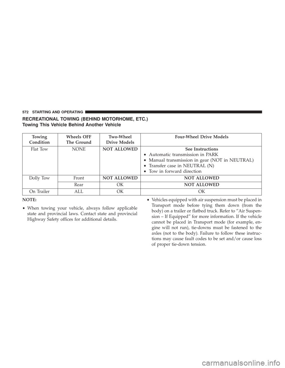
RECREATIONAL TOWING (BEHIND MOTORHOME, ETC.)
Towing This Vehicle Behind Another Vehicle
Towing
Condition Wheels OFF
The Ground Two-Wheel
Drive Models Four-Wheel Drive Models
Flat Tow NONENOT ALLOWED See Instructions
•Automatic transmission in PARK
• Manual transmission in gear (NOT in NEUTRAL)
• Transfer case in NEUTRAL (N)
• Tow in forward direction
Dolly Tow FrontNOT ALLOWED NOT ALLOWED
Rear OK NOT ALLOWED
On Trailer ALLOK OK
NOTE:
• When towing your vehicle, always follow applicable
state and provincial laws. Contact state and provincial
Highway Safety offices for additional details. •
Vehicles equipped with air suspension must be placed in
Transport mode before tying them down (from the
body) on a trailer or flatbed truck. Refer to “Air Suspen-
sion – If Equipped” for more information. If the vehicle
cannot be placed in Transport mode (for example, en-
gine will not run), tie-downs must be fastened to the
axles (not to the body). Failure to follow these instruc-
tions may cause fault codes to be set and/or cause loss
of proper tie-down tension.
572 STARTING AND OPERATING
Page 575 of 734
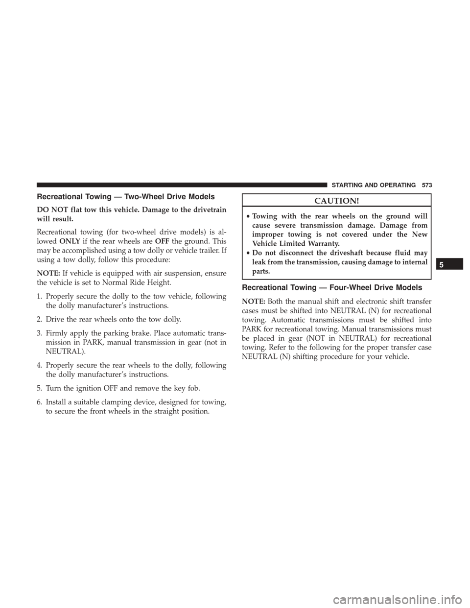
Recreational Towing — Two-Wheel Drive Models
DO NOT flat tow this vehicle. Damage to the drivetrain
will result.
Recreational towing (for two-wheel drive models) is al-
lowedONLY if the rear wheels are OFFthe ground. This
may be accomplished using a tow dolly or vehicle trailer. If
using a tow dolly, follow this procedure:
NOTE: If vehicle is equipped with air suspension, ensure
the vehicle is set to Normal Ride Height.
1. Properly secure the dolly to the tow vehicle, following the dolly manufacturer’s instructions.
2. Drive the rear wheels onto the tow dolly.
3. Firmly apply the parking brake. Place automatic trans- mission in PARK, manual transmission in gear (not in
NEUTRAL).
4. Properly secure the rear wheels to the dolly, following the dolly manufacturer’s instructions.
5. Turn the ignition OFF and remove the key fob.
6. Install a suitable clamping device, designed for towing, to secure the front wheels in the straight position.
CAUTION!
•Towing with the rear wheels on the ground will
cause severe transmission damage. Damage from
improper towing is not covered under the New
Vehicle Limited Warranty.
•
Do not disconnect the driveshaft because fluid may
leak from the transmission, causing damage to internal
parts.
Recreational Towing — Four-Wheel Drive Models
NOTE: Both the manual shift and electronic shift transfer
cases must be shifted into NEUTRAL (N) for recreational
towing. Automatic transmissions must be shifted into
PARK for recreational towing. Manual transmissions must
be placed in gear (NOT in NEUTRAL) for recreational
towing. Refer to the following for the proper transfer case
NEUTRAL (N) shifting procedure for your vehicle.
5
STARTING AND OPERATING 573
Page 577 of 734

CAUTION!
It is necessary to follow these steps to be certain that
the transfer case is fully in NEUTRAL (N) before
recreational towing to prevent damage to internal
parts.
1. Bring the vehicle to a complete stop, with the engine running. Firmly apply the parking brake.
2. Shift the transmission to NEUTRAL.
NOTE: If vehicle is equipped with air suspension, ensure
the vehicle is set to Normal Ride Height.
3. Press and hold the brake pedal.
4. Depress the clutch pedal on a manual transmission.
5. With manual shift transfer case, shift the transfer case lever into NEUTRAL (N).
• With electronic shift transfer case, push and hold the
transfer case NEUTRAL (N) button. Some models
have a small, recessed “N” button (at the center of the
transfer case switches) that must be pushed using a
ballpoint pen or similar object. Other models have a
rectangular NEUTRAL switch, below the rotary trans-
fer case control knob. The NEUTRAL (N) indicator light will blink while the shift is in progress. The light
will stop blinking (stay on solid) when the shift to
NEUTRAL (N) is complete. After the shift is completed
and the NEUTRAL (N) light stays on, release the
NEUTRAL (N) button.
6. Release the parking brake.
7. Shift the transmission into REVERSE.
8. Release the brake pedal (and clutch pedal on manual transmissions) for five seconds and ensure that there is
no vehicle movement.
9. Repeat steps 7 and 8 with automatic transmission in DRIVE or manual transmission in first gear.
10. Shift the transmission to NEUTRAL. Firmly apply the parking brake. Turn OFF the engine. For vehicles with
Keyless Enter-N-Go, push and hold the ENGINE
START/STOP button until the engine shuts off.
11. Shift the transmission into PARK or place manual transmission in gear (NOT in Neutral). On 8-speed
transmissions the shifter will automatically select
PARK when the engine is turned off.
5
STARTING AND OPERATING 575
Page 578 of 734

12. Turn the ignition to the OFF mode, then cycle theignition to the RUN mode and back to the OFF mode.
Remove the key fob from the ignition.
13. Attach the vehicle to the tow vehicle using a suitable tow bar.
14. Release the parking brake.
NOTE: With electronic shift transfer case:
• Steps 2 through 4 are requirements that must be met
before pushing the NEUTRAL (N) button, and must
continue to be met until the shift has been completed. If
any of these requirements are not met before pushing
the NEUTRAL (N) button or are no longer met during
the shift, the NEUTRAL (N) indicator light will flash
continuously until all requirements are met or until the
NEUTRAL (N) button is released.
• The ignition must be in the ON/RUN mode for a shift to
take place and for the position indicator lights to be
operable. If the ignition is not in the ON/RUN mode, the
shift will not take place and no position indicator lights
will be on or flashing.
• A flashing NEUTRAL (N) position indicator light indi-
cates that shift requirements have not been met. •
If the vehicle is equipped with air suspension, the engine
should be started and left running for a minimum of 60
seconds (with all the doors closed) at least once every 24
hours. This process allows the air suspension to adjust
the vehicle’s ride height to compensate for temperature
effects.
Shifting Out Of NEUTRAL (N)
Use the following procedure to prepare your vehicle for
normal usage:
1. Bring the vehicle to a complete stop, leaving it con- nected to the tow vehicle.
2. Firmly apply the parking brake.
3. Press and hold the brake pedal.
4. Start the engine. Shift the transmission into NEUTRAL. Depress the clutch pedal on a manual transmission.
• With manual shift transfer case, shift the transfer case
lever to the desired position.
• With electronic shift transfer case with rotary selector
switch, push and hold the transfer case NEUTRAL (N)
button until the NEUTRAL (N) indicator light turns
off. After the NEUTRAL (N) indicator light turns off,
release the NEUTRAL (N) button. After the NEUTRAL
576 STARTING AND OPERATING
Page 582 of 734
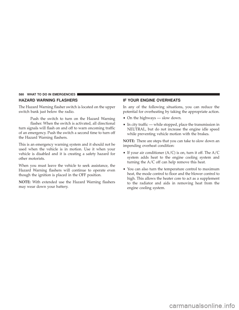
HAZARD WARNING FLASHERS
The Hazard Warning flasher switch is located on the upper
switch bank just below the radio.Push the switch to turn on the Hazard Warning
flasher. When the switch is activated, all directional
turn signals will flash on and off to warn oncoming traffic
of an emergency. Push the switch a second time to turn off
the Hazard Warning flashers.
This is an emergency warning system and it should not be
used when the vehicle is in motion. Use it when your
vehicle is disabled and it is creating a safety hazard for
other motorists.
When you must leave the vehicle to seek assistance, the
Hazard Warning flashers will continue to operate even
though the ignition is placed in the OFF position.
NOTE: With extended use the Hazard Warning flashers
may wear down your battery.
IF YOUR ENGINE OVERHEATS
In any of the following situations, you can reduce the
potential for overheating by taking the appropriate action.
• On the highways — slow down.
• In city traffic — while stopped, place the transmission in
NEUTRAL, but do not increase the engine idle speed
while preventing vehicle motion with the brakes.
NOTE: There are steps that you can take to slow down an
impending overheat condition:
• If your air conditioner (A/C) is on, turn it off. The A/C
system adds heat to the engine cooling system and
turning the A/C off can help remove this heat.
• You can also turn the temperature control to maximum
heat, the mode control to floor and the blower control to
high. This allows the heater core to act as a supplement
to the radiator and aids in removing heat from the
engine cooling system.
580 WHAT TO DO IN EMERGENCIES
Page 583 of 734
WARNING!
You or others can be badly burned by hot engine
coolant (antifreeze) or steam from your radiator. If you
see or hear steam coming from under the hood, do not
open the hood until the radiator has had time to cool.
Never try to open a cooling system pressure cap when
the radiator or coolant bottle is hot.
CAUTION!
Driving with a hot cooling system could damage your
vehicle. If the temperature gauge reads HOT (H), pull
over and stop the vehicle. Idle the vehicle with the air
conditioner turned off until the pointer drops back
into the normal range. If the pointer remains on HOT
(H), and you hear continuous chimes, turn the engine
off immediately and call for service.
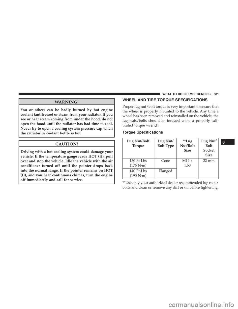
WHEEL AND TIRE TORQUE SPECIFICATIONS
Proper lug nut/bolt torque is very important to ensure that
the wheel is properly mounted to the vehicle. Any time a
wheel has been removed and reinstalled on the vehicle, the
lug nuts/bolts should be torqued using a properly cali-
brated torque wrench.
Torque Specifications
Lug Nut/BoltTorque Lug Nut/
Bolt Type **Lug
Nut/Bolt Size Lug Nut/
Bolt
Socket Size
130 Ft-Lbs (176 N·m) Cone M14 x
1.5022 mm
140 Ft-Lbs (190 N·m) Flanged
**Use only your authorized dealer recommended lug nuts/
bolts and clean or remove any dirt or oil before tightening.6
WHAT TO DO IN EMERGENCIES 581