clock Ram 1500 2018 Owner's Manual
[x] Cancel search | Manufacturer: RAM, Model Year: 2018, Model line: 1500, Model: Ram 1500 2018Pages: 372, PDF Size: 7.1 MB
Page 215 of 372
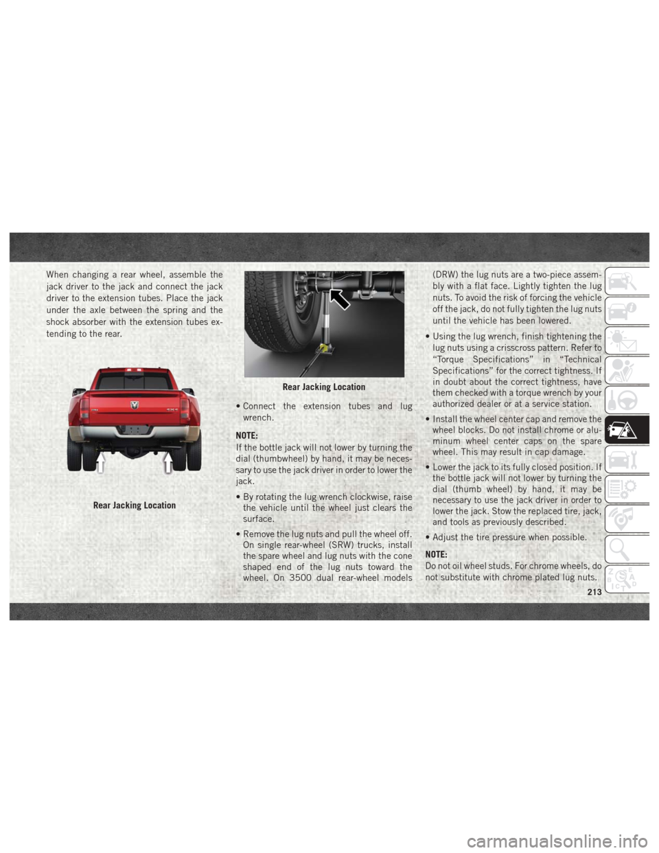
When changing a rear wheel, assemble the
jack driver to the jack and connect the jack
driver to the extension tubes. Place the jack
under the axle between the spring and the
shock absorber with the extension tubes ex-
tending to the rear.• Connect the extension tubes and lugwrench.
NOTE:
If the bottle jack will not lower by turning the
dial (thumbwheel) by hand, it may be neces-
sary to use the jack driver in order to lower the
jack.
• By rotating the lug wrench clockwise, raise the vehicle until the wheel just clears the
surface.
• Remove the lug nuts and pull the wheel off. On single rear-wheel (SRW) trucks, install
the spare wheel and lug nuts with the cone
shaped end of the lug nuts toward the
wheel. On 3500 dual rear-wheel models (DRW) the lug nuts are a two-piece assem-
bly with a flat face. Lightly tighten the lug
nuts. To avoid the risk of forcing the vehicle
off the jack, do not fully tighten the lug nuts
until the vehicle has been lowered.
• Using the lug wrench, finish tightening the lug nuts using a crisscross pattern. Refer to
“Torque Specifications” in “Technical
Specifications” for the correct tightness. If
in doubt about the correct tightness, have
them checked with a torque wrench by your
authorized dealer or at a service station.
• Install the wheel center cap and remove the wheel blocks. Do not install chrome or alu-
minum wheel center caps on the spare
wheel. This may result in cap damage.
• Lower the jack to its fully closed position. If the bottle jack will not lower by turning the
dial (thumb wheel) by hand, it may be
necessary to use the jack driver in order to
lower the jack. Stow the replaced tire, jack,
and tools as previously described.
• Adjust the tire pressure when possible.
NOTE:
Do not oil wheel studs. For chrome wheels, do
not substitute with chrome plated lug nuts.
Rear Jacking Location
Rear Jacking Location
213
Page 216 of 372
To Stow The Flat Or Spare
NOTE:
RAM 1500 vehicles equipped with alumi-
num wheels cannot be stored under the ve-
hicle because the wheel retainer will not fit
through the wheel pilot hole. Secure the flat
tire in the bed of the truck. Have the flat tire
repaired or replaced immediately.
1. Turn the wheel so that the valve stem isdown. Slide the wheel retainer through
the center of the wheel and position it
properly across the wheel opening.
2. For convenience in checking the spare tire inflation, stow with the valve stem toward
the rear of the vehicle.
3. Attach the lug wrench to the extension tubes with the curved angle facing away
from the vehicle. Rotate the lug wrench
handle clockwise until the wheel is drawn
into place against the underside of the
vehicle. Continue to rotate until you feel
the winch mechanism slip, or click three
or four times. It cannot be overtightened.
Push against the tire several times to be
sure it is firmly in place.
WARNING!
• Do not attempt to change a tire on theside of the vehicle close to moving traf-
fic. Pull far enough off the road to avoid
the danger of being hit when operating
the jack or changing the wheel.
• Being under a jacked-up vehicle is dan-
gerous. The vehicle could slip off the
jack and fall on you. You could be
crushed. Never put any part of your body
under a vehicle that is on a jack.
• Never start or run the engine while the
vehicle is on a jack. If you need to get
under a raised vehicle, take it to your
authorized dealer where it can be raised
on a lift.
• The jack is designed to be used as a tool
for changing tires only. The jack should
not be used to lift the vehicle for service
purposes. The vehicle should be jacked
on a firm level surface only. Avoid ice or
slippery areas.
• Do not attempt to change a tire on the
side of the vehicle close to moving traf-
fic, pull far enough off the road to avoid
WARNING!
the danger of being hit when operating
the jack or changing the wheel.
• Carefully follow these tire changing
warnings to help prevent personal injury
or damage to your vehicle:• Always park on a firm, level surface
as far from the edge of the roadway
as possible before raising the ve-
hicle.
• Turn on the Hazard Warning flash-
ers.
• Block the wheel diagonally opposite
the wheel to be raised.
• Set the parking brake firmly and set
an automatic transmission in
PARK; a manual transmission in
REVERSE.
• Do not let anyone sit in the vehicle
when it is on a jack.
• Do not get under the vehicle when it
is on a jack.
• Only use the jack in the positions
indicated and for lifting this vehicle
during a tire change.
IN CASE OF EMERGENCY
214
Page 217 of 372

WARNING!
• If working on or near a roadway, beextremely careful of motor traffic.
• To assure that spare tires, flat or
inflated, are securely stowed,
spares must be stowed with the
valve stem facing the ground.
• Raising the vehicle higher than nec-
essary can make the vehicle less
stable. It could slip off the jack and
hurt someone near it. Raise the ve-
hicle only enough to remove the
tire.
• To avoid the risk of forcing the ve-
hicle off the jack, do not fully
tighten the wheel bolts until the
vehicle has been lowered. Failure to
follow this warning may result in
personal injury.
• To avoid possible personal injury,
handle the wheel covers with care to
avoid contact with any sharp edges.
WARNING!
• A loose tire or jack thrown forward ina collision or hard stop could en-
danger the occupants of the ve-
hicle. Always stow the jack parts
and the spare tire in the places
provided.
• A loose tire thrown forward in a
collision or hard stop could injure
the occupants in the vehicle. Have
the deflated (flat) tire repaired or
replaced immediately.
CAUTION!
• Do not attempt to raise the vehicle byjacking on locations other than those
indicated in the Jacking Instructions for
this vehicle.
• Before raising the wheel off the ground,
make sure that the jack will not damage
surrounding truck parts and adjust the
jack position as required.
• Use a back and forth motion to remove
the hub cap. Do not use a twisting mo-
CAUTION!
tion when removing the hub cap, dam-
age to the hub cap; finish may occur.
• The rear hubcaps on the dual rear wheel
has two pry off notches. Make sure that
the hook of the jack handle driver is
located squarely in the cap notch before
attempting to pull off.
Reinstalling The Jack And Tools
1500 Series Trucks
1. Tighten the jack all the way down by turning the jack turn-screw clockwise un-
til the jack is snug.
215
Page 218 of 372

2. Position the jack and tool bag. Make surethe lug wrench is under the jack near the
jack turn-screw. 3. Secure the tool bag straps to the jack.
4. Place the jack and tools in the storage
position holding the jack by the jack turn-
screw, slip the jack and tools under the
seat so that the bottom slot engages into
the fastener on the floor.
NOTE:
Ensure that the jack slides into the front
hold down location. 5. Turn the wing bolt clockwise to secure to
the floor pan. Reinstall the plastic cover.
Jack And Tool Bag
Floor Fastener Location
Wing Bolt Location
IN CASE OF EMERGENCY
216
Page 219 of 372

2500/3500 Series Trucks
1. Tighten the jack all the way down byturning the jack turn-screw clockwise un-
til the jack is snug.
2. Position the jack and tools into bracket assembly. Make sure the lug wrench is
under the jack near the jack turn-screw.
Snap tools into bracket assembly clips.
Install the jack into bracket assembly and
turn screw until jack is snug into bracket
assembly.
3. Place the jack and tool bracket assembly in the storage position holding the jack by
the jack turn-screw, slip the jack and tools
under the seat so that the bottom slot
engages into the fastener on the floor. NOTE:
Ensure that the jack and tool bracket
assembly slides into the front hold down
location.
4. Turn the wing bolt clockwise to secure to the floor pan. Reinstall the plastic cover.Hub Caps/Wheel Covers — If
Equipped
The hub caps must be removed before raising
the vehicle off the ground.
CAUTION!
Use extreme caution when removing the
front and rear center caps. Damage can
occur to the center cap and/or the wheel if
screwdriver type tools are used. A pulling
motion, not a pry off motion, is recom-
mended to remove the caps.
For single rear wheel (SRW) models, use the
flat blade on the end of the lug wrench to pull
the hub cap off. Insert the blade end into the
pull off notch and carefully pull the hub cap
off with a back and forth motion.
On 3500 models with dual rear wheels
(DRW), you must first remove the hub caps.
The jack handle driver has a hook at one end
that will fit in the pull off notch of the rear
hub caps. Position the hook and pull straight
out on the ratchet firmly. The hub cap should
pop off. The wheel skins can now be removed.
For the front hub cap, use the flat blade on
Floor Fastener Location
217
Page 252 of 372
nate and an audible chime will be heard. At
this point, you should stop the engine and
drain the water from the filter housing.
CAUTION!
If the “Water In Fuel Indicator Light” re-
mains on, DO NOT START the engine be-
fore you drain water from the fuel filter to
avoid engine damage.
If the “Water In Fuel Indicator Light” comes
on and a single chime is heard while you are
driving, or with the ignition in the ON posi-
tion, there may be a problem with your water
separator wiring or sensor. See your autho-
rized dealer for service.
Upon proper draining of the water from the
fuel filter, the “Water In Fuel Indicator Light”
will remain illuminated for approximately
10 seconds. If the water was drained while
the engine was running, the “Water In Fuel
Indicator Light” may remain on for approxi-
mately three minutes. NOTE:
Care should be taken in disposing of used
fluids from your vehicle. Used fluids, indis-
criminately discarded, can present a problem
to the environment. Contact an authorized
dealer, service station, or government agency
for advice on recycling programs and for
where used fluids and filters can be properly
disposed of in your area.
Drain the fuel/water separator filter when the
“Water In Fuel Indicator Light” is ON. Within
10 minutes of vehicle shutdown, turn the
filter drain valve (located on the bottom of the
filter housing) counterclockwise to drain fuel/
water, then turn the ignition switch to the ON
position, and allow any accumulated water to
drain. Leave the drain valve open until all
water and contaminants have been removed.
When clean fuel is visible, close the drain
valve by turning it clockwise, and turn the
ignition switch to OFF.
If more than two ounces or 60 milliliters of
fuel have been drained, follow the directions
for “Priming If The Engine Has Run Out Of
Fuel.”
Underbody Mounted Fuel Filter
Replacement
NOTE:
Using a fuel filter that does not meet the
manufacturer's filtration and water separat-
ing requirements can severely impact fuel
system life and reliability.
CAUTION!
• Diesel fuel will damage blacktop paving
surfaces. Drain the filter into an appro-
priate container.
• Do not prefill the fuel filter when install-
ing a new fuel filter. There is a possibility
debris could be introduced into the fuel
filter during this action. It is best to
install the filter dry and allow the in-tank
lift pump to prime the fuel system.
1. Turn engine off.
2. Place a drain pan under the fuel filter assembly.
3. Open the water drain valve, and let any accumulated water drain.
4. Close the water drain valve.
SERVICING AND MAINTENANCE
250
Page 253 of 372

5. Remove bottom cover using a strapwrench. Rotate counterclockwise for re-
moval. Remove the used o-ring and dis-
card it.
6. Remove the used filter cartridge from the housing and dispose of it according to
your local regulations.
7. Wipe the sealing surfaces of the lid and housing clean.
8. Install a new o-ring into the ring groove on the filter housing and lubricate with clean
engine oil.
NOTE:
WIF (Water In Fuel) sensor is re-usable. Ser-
vice kit comes with new o-ring for filter can-
ister and WIF sensor.
Priming If The Engine Has Run Out
Of Fuel
WARNING!
Do not open the high pressure fuel system
with the engine running. Engine operation
causes high fuel pressure. High pressure
WARNING!
fuel spray can cause serious injury or
death.
1. Add a substantial amount of fuel to the tank, approximately 2 to 5 gal (8L to
19L).
2. Press ignition switch twice without your foot on brake to put vehicle in Run posi-
tion. This will activate the in tank fuel
pump for approximately 30 seconds. Re-
peat this process twice.
3. Start the engine using the “Normal Start- ing” procedure. Refer to “Starting The
Engine” in “Starting and Operating” for
further information.
CAUTION!
The starter motor will engage for approxi-
mately 30 seconds at a time. Allow two
minutes between cranking intervals.
NOTE:
The engine may run rough until the air is
forced from all the fuel lines.
WARNING!
Do not use alcohol or gasoline as a fuel
blending agent. They can be unstable un-
der certain conditions and be hazardous or
explosive when mixed with diesel fuel.
CAUTION!
Due to lack of lubricants in alcohol or
gasoline, the use of these fuels can cause
damage to the fuel system.
NOTE:
• Use of biodiesel mixture in excess of 20% can negatively impact the fuel filter's abil-
ity to separate water from the fuel, resulting
in high pressure fuel system corrosion or
damage.
• In addition, commercially available fuel ad- ditives are not necessary for the proper
operation of your diesel engine.
• For extreme cold conditions, "Mopar Pre- mium Diesel Fuel Treatment" is recom-
mended to assist with cold starting.
251
Page 256 of 372
position, there may be a problem with your
water separator wiring or sensor. See your
authorized dealer for service.
Upon proper draining of the water from both
fuel filters, the “Water In Fuel Indicator
Light” will remain illuminated for approxi-
mately 10 seconds. If the water was drained
while the engine was running, the “Water In
Fuel Indicator Light” may remain on for ap-
proximately three minutes.
NOTE:
Care should be taken in disposing of used
fluids from your vehicle. Used fluids, indis-
criminately discarded, can present a problem
to the environment. Contact an authorized
dealer, service station, or government agency
for advice on recycling programs and for
where used fluids and filters can be properly
disposed of in your area.
Drain the fuel/water separator filters when
the “Water In Fuel Indicator Light” is ON.
Within 10 minutes of vehicle shutdown, turn
the engine mounted filter drain valve (located
on the side of the filter assembly) counter-
clockwise 1/4 turn, and turn the under body
mounted filter drain valve (located on thebottom of the filter assembly) counterclock
wise 1 full turn. Then turn the ignition switch
to the ON position, and allow any accumu-
lated water to drain. Leave the drain valve
open until all water and contaminants have
been removed. When clean fuel is visible,
close the drain valves by turning them fully
clockwise, and turn the ignition switch to
OFF.
If more than a couple ounces/milliliters of
fuel have been drained, follow the directions
for “Priming If The Engine Has Run Out Of
Fuel.”
Engine Mounted Fuel Filter
Replacement
NOTE:
• Using a fuel filter that does not meet the
manufacturer's filtration and water separat-
ing requirements can severely impact fuel
system life and reliability.
• The engine mounted filter housing is equipped with a No-Filter-No-Run (NFNR)
feature. Engine will not run if:
1. No filter is installed. 2. Inferior/Non-approved filter is used.
Use of OEM filter is required to ensure
vehicle will run.
CAUTION!
• Diesel fuel will damage blacktop pavingsurfaces. Drain the filter into an appro-
priate container.
• Do not prefill the fuel filter when install-
ing a new fuel filter. There is a possibility
debris could be introduced into the fuel
filter during this action. It is best to
install the filter dry and allow the in-tank
lift pump to prime the fuel system.
1. Ensure engine is turned off.
2. Place drain pan under the fuel filter drain hose.
3. Open the water drain valve 1/4 turn coun- terclockwise and completely drain fuel
and water into the approved container.
4. Close the water drain valve.
5. Remove lid using a socket or strap wrench. Rotate counterclockwise for re-
moval. Remove used o-ring and discard it.
SERVICING AND MAINTENANCE
254
Page 257 of 372

6. Remove the used filter cartridge from thehousing and dispose of according to your
local regulations.
7. Wipe clean the sealing surfaces of the lid and housing.
8. Install new o-ring back into ring groove on the filter housing and lubricate with clean
engine oil.
9. Remove new filter cartridge from plastic bag and install into housing.
NOTE:
Do not remove cartridge from bag until
you reach this step in order to keep car-
tridge clean.
10. Push down on the cartridge to ensure it is properly seated. Do not pre-fill the filter
housing with fuel.
11. Install lid onto housing and tighten to 22.5 ft lbs (30.5 N.m). Do not over-
tighten the lid.
12. Prime the engine using the procedure in “Priming If The Engine Has Run Out Of
Fuel.” Then start the engine and confirm
there are no leaks.Underbody Mounted Fuel Filter
Replacement
NOTE:
• Using a fuel filter that does not meet themanufacturer's filtration and water separat-
ing requirements can severely impact fuel
system life and reliability.
• The underbody mounted filter housing will cause the engine not to run if:
1. No filter is installed.
CAUTION!
• Diesel fuel will damage blacktop paving surfaces. Drain the filter into an appro-
priate container.
• Do not prefill the fuel filter when install-
ing a new fuel filter. There is a possibility
debris could be introduced into the fuel
filter during this action. It is best to
install the filter dry and allow the in-tank
lift pump to prime the fuel system.
1. Ensure engine is turned off. 2. Place drain pan under the fuel filter drain
hose.
3. Open the water drain valve 1 full turn counterclockwise and completely drain
fuel and water into the approved
container.
4. Close the water drain valve.
5. Remove lid using a socket or strap wrench. Rotate counterclockwise for re-
moval. Remove used o-ring and discard it.
6. Remove the used filter cartridge from the housing and dispose of according to your
local regulations.
7. Wipe clean the sealing surfaces of the lid and housing.
8. Install new o-ring back into ring groove on the filter housing and lubricate with clean
engine oil.
NOTE:
WIF sensor is re-usable. Service kit comes
with new o-ring for filter canister and WIF
sensor.
255
Page 291 of 372
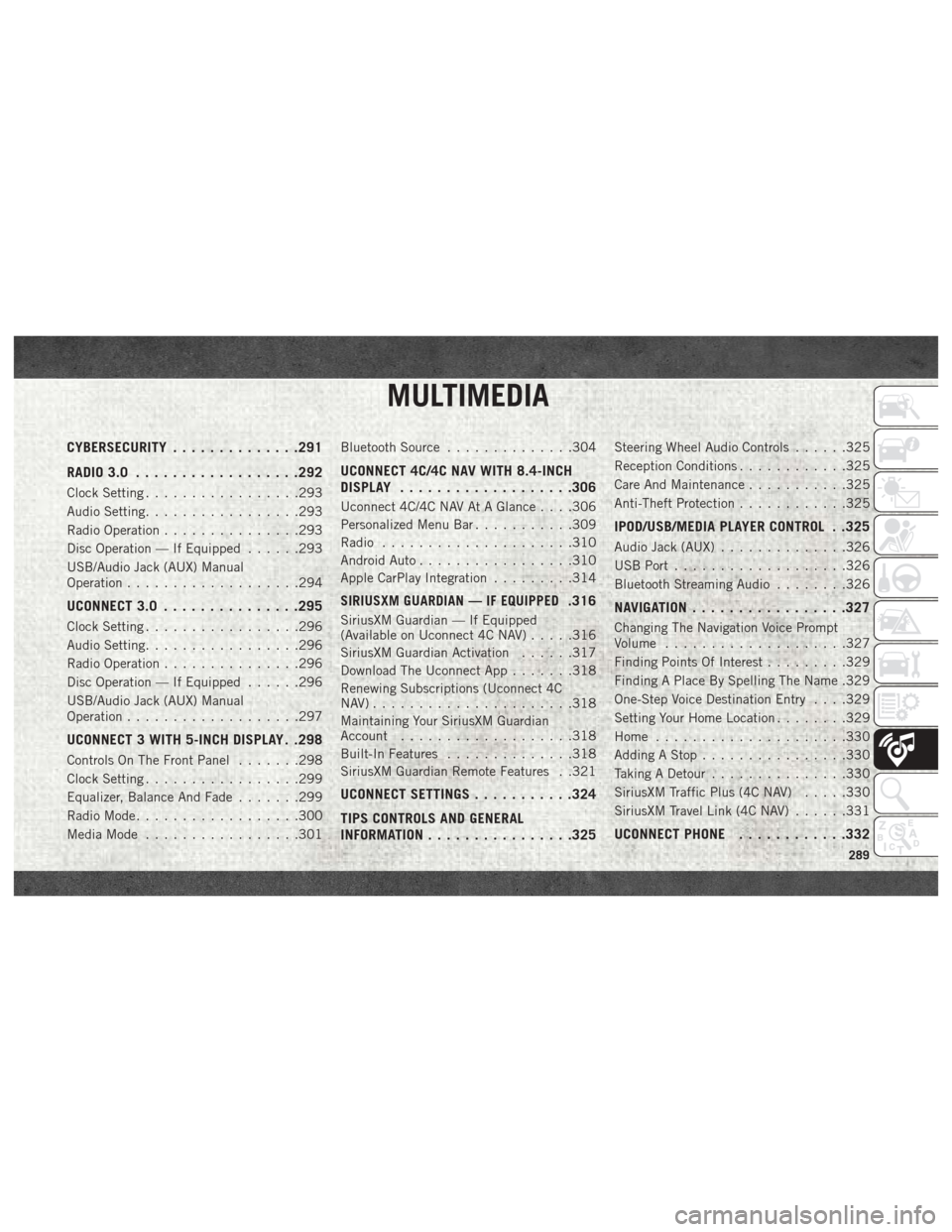
MULTIMEDIA
CYBERSECURITY..............291
RADIO 3.0 ................. .292
Clock Setting.................293
Audio Setting .................293
Radio Operation ...............293
Disc Operation — If Equipped ......293
USB/Audio Jack (AUX) Manual
Operation ...................294
UCONNECT 3.0 ...............295
Clock Setting.................296
Audio Setting .................296
Radio Operation ...............296
Disc Operation — If Equipped ......296
USB/Audio Jack (AUX) Manual
Operation ...................297
UCONNECT 3 WITH 5-INCH DISPLAY . .298
Controls On The Front Panel .......298
Clock Setting .................299
Equalizer, Balance And Fade .......299
Radio Mode ..................300
Media Mode .................301 Bluetooth Source
..............304
UCONNECT 4C/4C NAV WITH 8.4-INCH
DISPLAY.................. .306
Uconnect 4C/4C NAV At A Glance . . . .306
Personalized Menu Bar...........309
Radio .....................310
Android Auto .................310
Apple CarPlay Integration .........314
SIRIUSXM GUARDIAN — IF EQUIPPED.316
SiriusXM Guardian — If Equipped
(Available on Uconnect 4C NAV) .....316
SiriusXM Guardian Activation ......317
Download The Uconnect App .......318
Renewing Subscriptions (Uconnect 4C
NAV)......................318
Maintaining Your SiriusXM Guardian
Account ...................318
Built-In Features ..............318
SiriusXM Guardian Remote Features . .321
UCONNECT SETTINGS ...........324
TIPS CONTROLS AND GENERAL
INFORMATION ............... .325
Steering Wheel Audio Controls ......325
Reception Conditions ............325
Care And Maintenance ...........325
Anti-Theft Protection ............325
IPOD/USB/MEDIA PLAYER CONTROL . .325
Audio Jack (AUX)..............326
USB Port ...................326
Bluetooth Streaming Audio ........326
NAVIGATION................ .327
Changing The Navigation Voice Prompt
Volume....................327
Finding Points Of Interest .........329
Finding A Place By Spelling The Name .329
One-Step Voice Destination Entry . . . .329
Setting Your Home Location ........329
Home .....................330
Adding A Stop ................330
Taking A Detour ...............330
SiriusXM Traffic Plus (4C NAV) .....330
SiriusXM Travel Link (4C NAV) ......331
UCONNECT PHONE............332
MULTIMEDIA
289