reset Ram 1500 2018 User Guide
[x] Cancel search | Manufacturer: RAM, Model Year: 2018, Model line: 1500, Model: Ram 1500 2018Pages: 372, PDF Size: 7.1 MB
Page 24 of 372
2. This device must accept any interferencereceived, including interference that may
cause undesired operation.
NOTE:
Changes or modifications not expressly ap-
proved by the party responsible for compli-
ance could void the user’s authority to oper-
ate the equipment.
SEATS
Seats are a part of the Occupant Restraint
System of the vehicle.
WARNING!
• It is dangerous to ride in a cargo area, inside or outside of a vehicle. In a colli-
sion, people riding in these areas are
more likely to be seriously injured or
killed.
• Do not allow people to ride in any area of
your vehicle that is not equipped with
seats and seat belts. In a collision,
people riding in these areas are more
likely to be seriously injured or killed.
WARNING!
• Be sure everyone in your vehicle is in aseat and using a seat belt properly.
Driver Memory Seat — If
Equipped
This feature allows the driver to store up to
two different memory profiles for easy recall
through a memory switch. Each memory pro-
file contains desired position settings for the
driver’s seat, side mirrors, adjustable pedals
(if equipped) and a set of desired radio sta-
tion presets. Your remote keyless entry key
fob can also be programmed to recall the
same positions when the unlock button is
pushed.
NOTE:
Your vehicle is equipped with two key fobs,
one key fob can be linked to memory position
1 and the other key fob can be linked to
memory position 2.
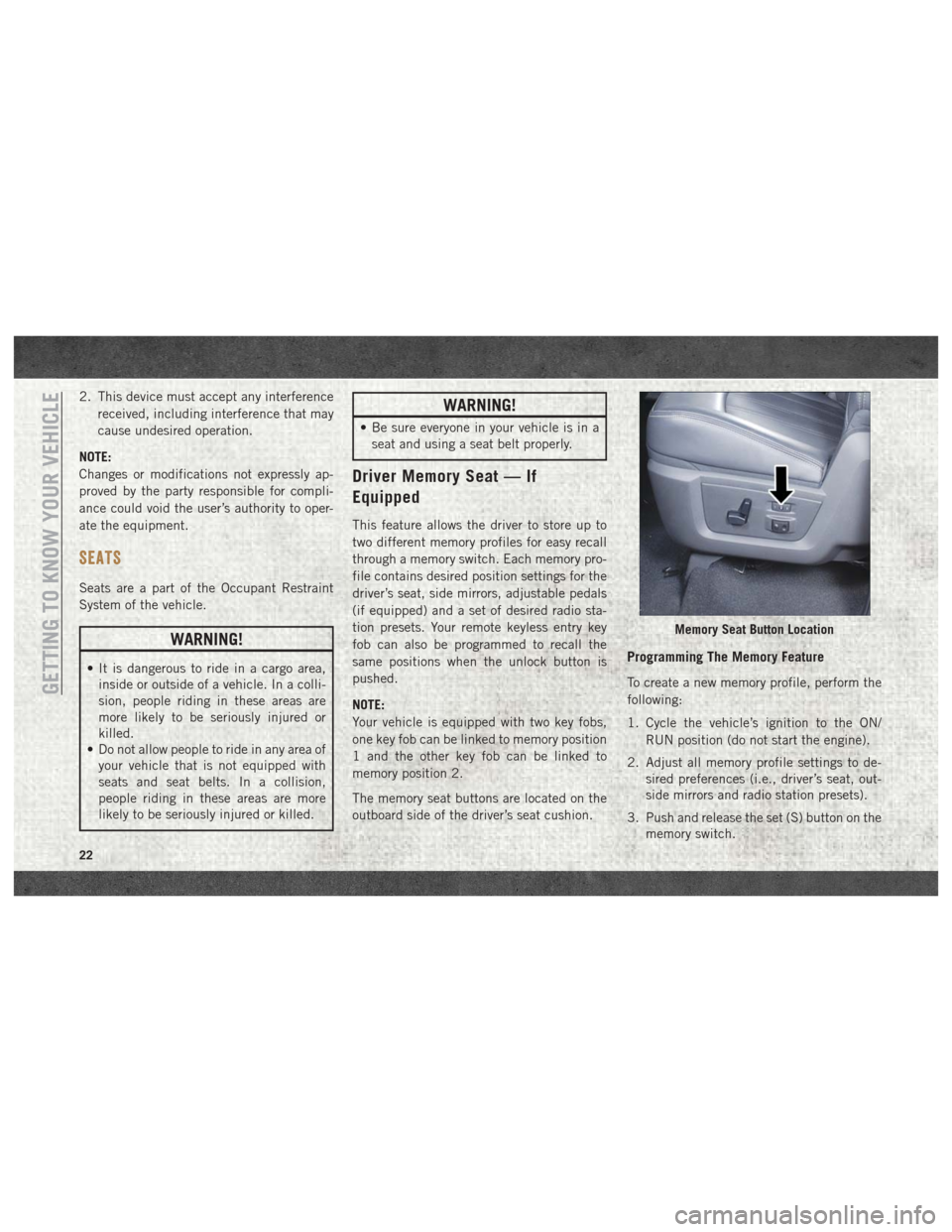
The memory seat buttons are located on the
outboard side of the driver’s seat cushion.
Programming The Memory Feature
To create a new memory profile, perform the
following:
1. Cycle the vehicle’s ignition to the ON/
RUN position (do not start the engine).
2. Adjust all memory profile settings to de- sired preferences (i.e., driver’s seat, out-
side mirrors and radio station presets).
3. Push and release the set (S) button on the memory switch.
Memory Seat Button Location
GETTING TO KNOW YOUR VEHICLE
22
Page 33 of 372

CAUTION!
trols. Pedal travel may become limited if
movement is stopped by an obstruction in
the adjustable pedal's path.
MIRRORS
Power Folding Outside Mirrors For
Standard And Trailer Tow — If
Equipped
If equipped with power folding mirrors, they
can be electrically folded rearward and un-
folded into the drive position.
The switch for the power folding mirrors is
located between the power mirror switches L
(left) and R (right). Push the switch once and
the mirrors will fold in, push the switch a
second time and the mirrors will return to the
normal driving position.
If the mirror is manually folded after electri-
cally cycled, a potential extra button push is
required to get the mirrors back to the homeposition. If the mirror does not electrically
fold, check for ice or dirt build up at the pivot
area which can cause excessive drag.
Resetting The Power Folding Outside Mirrors
You may need to reset the power folding
mirrors if the following occurs:
• The mirrors are accidentally blocked while
folding.
• The mirrors are accidentally manually folded/unfolded. • The mirrors come out of the unfolded posi-
tion.
• The mirrors shake and vibrate at normal driving speeds.
To Reset The Power Folding Mirrors:
1. Using the power folding mirror switch, move the mirror to its full forward
position.
2. Using the power folding mirror switch, move the mirror to the full retract position
(this may require multiple button
pushes). This resets them to their normal
position.
NOTE:
• The power fold mirrors are designed to operate while the vehicle is stationary or
traveling at moderate speeds. If you at-
tempt to power fold the mirrors at high
speeds they may not fully open or close. You
should slow down to a moderate speed and
complete the operation.
• When pushing the power fold button 10 or more times in one minute the system shuts
down for one minute to protect the motors
from over heating.
Power Folding Mirror Switch
31
Page 59 of 372
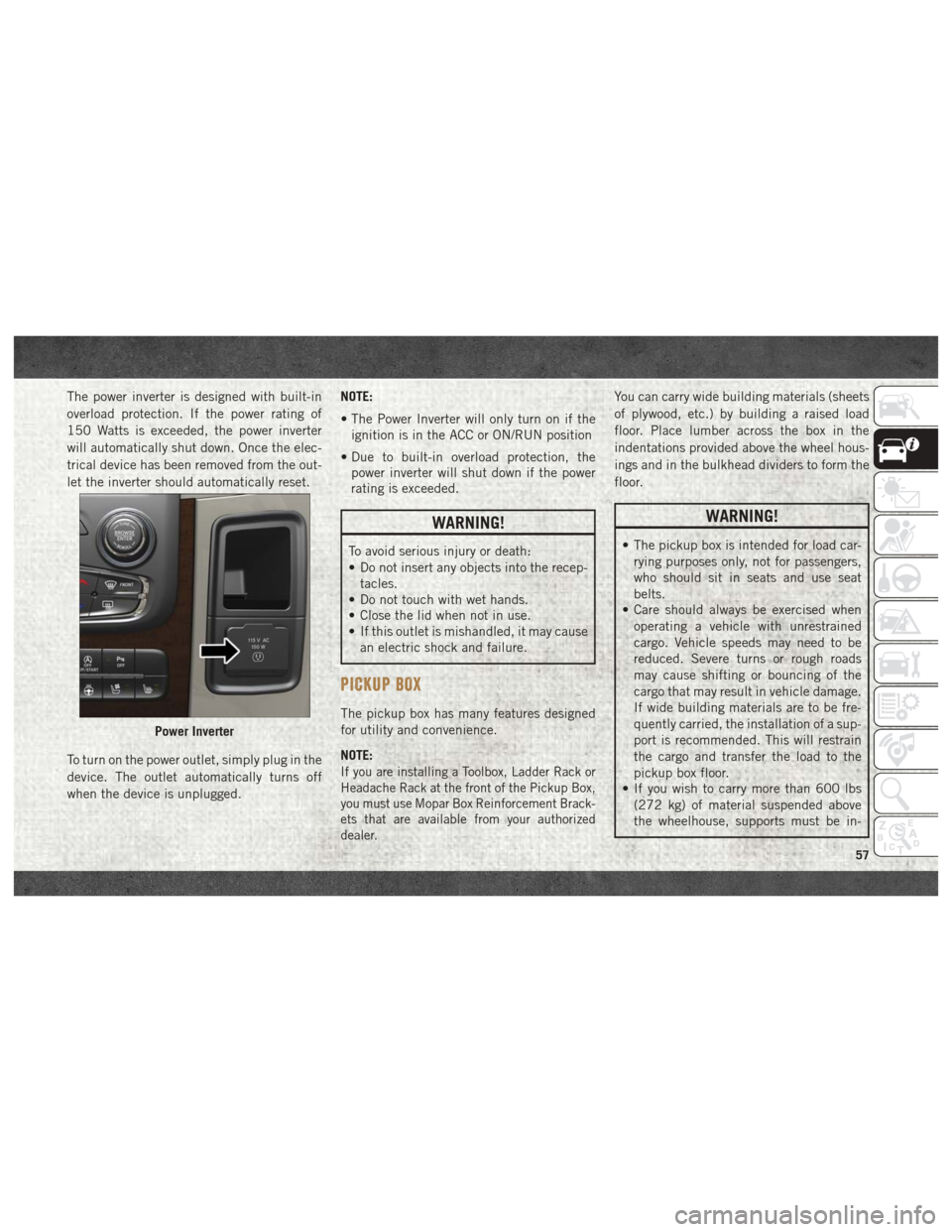
The power inverter is designed with built-in
overload protection. If the power rating of
150 Watts is exceeded, the power inverter
will automatically shut down. Once the elec-
trical device has been removed from the out-
let the inverter should automatically reset.
To turn on the power outlet, simply plug in the
device. The outlet automatically turns off
when the device is unplugged.NOTE:
• The Power Inverter will only turn on if the
ignition is in the ACC or ON/RUN position
• Due to built-in overload protection, the power inverter will shut down if the power
rating is exceeded.
WARNING!
To avoid serious injury or death:
• Do not insert any objects into the recep-
tacles.
• Do not touch with wet hands.
• Close the lid when not in use.
• If this outlet is mishandled, it may cause
an electric shock and failure.
PICKUP BOX
The pickup box has many features designed
for utility and convenience.
NOTE:
If you are installing a Toolbox, Ladder Rack or
Headache Rack at the front of the Pickup Box,
you must use Mopar Box Reinforcement Brack-
ets that are available from your authorized
dealer.
You can carry wide building materials (sheets
of plywood, etc.) by building a raised load
floor. Place lumber across the box in the
indentations provided above the wheel hous-
ings and in the bulkhead dividers to form the
floor.
WARNING!
• The pickup box is intended for load car-rying purposes only, not for passengers,
who should sit in seats and use seat
belts.
• Care should always be exercised when
operating a vehicle with unrestrained
cargo. Vehicle speeds may need to be
reduced. Severe turns or rough roads
may cause shifting or bouncing of the
cargo that may result in vehicle damage.
If wide building materials are to be fre-
quently carried, the installation of a sup-
port is recommended. This will restrain
the cargo and transfer the load to the
pickup box floor.
• If you wish to carry more than 600 lbs
(272 kg) of material suspended above
the wheelhouse, supports must be in-
Power Inverter
57
Page 67 of 372
GETTING TO KNOW YOUR INSTRUMENT PANEL
INSTRUMENT CLUSTER DISPLAY.....66
Instrument Cluster Display Controls ....66
Diesel Messages And Warnings — 3.0L
Diesel Engine .................67
Diesel Messages And Warnings — 6.7L
Cummins Diesel Engine ...........70
Oil Life Reset .................74
Instrument Cluster Display Programmable
Features ....................75
WARNING LIGHTS AND MESSAGES ....76
Red Warning Lights..............76
Yellow Warning Lights ............78
Yellow Indicator Lights ............82
Green Indicator Lights ............83
White Indicator Lights ............84
Blue Indicator Lights .............84
ONBOARD DIAGNOSTIC SYSTEM —
OBDII .....................84
Onboard Diagnostic System (OBD II)
Cybersecurity.................85
GETTING TO KNOW YOUR INSTRUMENT PANEL
65
Page 69 of 372
• Push and release thedownarrow button to
scroll downward through the main menu
items, submenu screen, and vehicle set-
tings.
• Push and release the rightarrow button to
access/select the information screens or
submenu screens of a main menu item.
Push and hold the RIGHT arrow button for
two seconds to reset displayed/selected
features that can be reset.
• Push and release the leftarrow button to
access/select the information screens, sub-
menu screens of a main menu item, or to
return to the main menu.
Diesel Messages And Warnings —
3.0L Diesel Engine
Diesel Particulate Filter (DPF) Messages
WARNING!
A hot exhaust system can start a fire if you
park over materials that can burn. Such
materials might be grass or leaves coming
into contact with your exhaust system. Do
WARNING!
not park or operate your vehicle in areas
where your exhaust system can contact
anything that can burn.
Your vehicle has the ability to alert you to
additional maintenance required on your ve-
hicle or engine. Refer to the following mes-
sages that may be displayed on your instru-
ment cluster:
• Exhaust Filter XX% Full Safely Drive at High-
way Speeds to Remedy — This message will
be displayed in the instrument cluster if the
exhaust particulate filter reaches 80% of
its maximum storage capacity. Under con-
ditions of exclusive short duration and low
speed driving cycles, your diesel engine
and exhaust after-treatment system may
never reach the conditions required to
cleanse the filter to remove the trapped
PM. If this occurs, the “Exhaust Filter XX%
Full Safely Drive at Highway Speeds to
Remedy” message will be displayed in the
instrument cluster display. If this message
is displayed, you will hear one chime to
assist in alerting you of this condition. By simply driving your vehicle at highway
speeds for up to 20 minutes, you can rem-
edy the condition in the particulate filter
system and allow your diesel engine and
exhaust after-treatment system to cleanse
the filter to remove the trapped PM and
restore the system to normal operating con-
dition.
• Exhaust System — Regeneration In Process
Exhaust Filter XX% Full — This message
indicates that the Diesel Particulate Filter
(DPF) is self-cleaning. Maintain your cur-
rent driving condition until regeneration is
completed.
• Exhaust System — Regeneration Completed
— This message indicates that the Diesel
Particulate Filter (DPF) self-cleaning is
completed. If this message is displayed,
you will hear one chime to assist in alerting
you of this condition.
• Exhaust Service Required — See Dealer Now
— This messages indicates regeneration
has been disabled due to a system malfunc-
67
Page 70 of 372
tion. At this point the engine Powertrain
Control Module (PCM) will register a fault
code, the instrument panel will display a
MIL light.
CAUTION!
See your authorized dealer, as damage to
the exhaust system could occur soon with
continued operation.
• Exhaust Filter Full — Power Reduced See
Dealer — This message indicates the PCM
has derated the engine to limit the likeli-
hood of permanent damage to the after-
treatment system. If this condition is not
corrected and a dealer service is not per-
formed, extensive exhaust after-treatment
damage can occur. To correct this condition
it will be necessary to have your vehicle
serviced by your local authorized dealer. NOTE:
Failing to follow the oil change indicator,
changing your oil and resetting the oil change
indicator by 0 miles remaining will prevent
the diesel exhaust filter from performing it's
cleaning routine. This will shortly result in a
Malfunction Indicator Light (MIL) and re-
duced engine power. Only an authorized
dealer will be able to correct this condition.
CAUTION!
See your authorized dealer, as damage to
the exhaust system could occur soon with
continued operation.
Diesel Exhaust Fluid (DEF) Warning Mes-
sages
Your vehicle will begin displaying warning
messages when the DEF level reaches a driv-
ing range of approximately 500 miles
(800 km). If the following warning message
sequence is ignored, your vehicle may not
restart unless DEF is added with in the dis-
played mileage shown in the cluster mes-
sage. •
Engine Will Not Restart in XXXX mi DEF Low
Refill Soon — This message will display
when DEF driving range is less than
500 miles, DEF fluid top off is required
with in the displayed mileage. The message
will be displayed in the cluster during ve-
hicle start up with the current allowed mile-
age and accompanied by a single chime.
The remaining mileage can be pulled up
anytime by way of the “Messages” list
within the instrument cluster display.
• Engine Will Not Restart in XXXX mi Refill DEF
— This message will display when DEF
driving range is less than 200 miles. It is
also displayed at 150 miles and 100 miles.
DEF fluid top off is required with in the
displayed mileage. The message will be
displayed in the instrument cluster display
during vehicle start up with an updated
distance mileage, and it will be accompa-
nied by a single chime. Starting at
100 miles, remaining range will be con-
tinuously displayed while operating the ve-
hicle. Chimes will also accompany the 75,
50 and 25 mile remaining distances. The
DEF Low telltale will be on continuously
until DEF fluid is topped off.
GETTING TO KNOW YOUR INSTRUMENT PANEL
68
Page 72 of 372
See Dealer message is displayed on the
next subsequent restart. Your engine will
not start unless your vehicle is serviced by
your authorized dealer. The message will be
accompanied by a single chime. Your Mal-
function Indicator Light will be continu-
ously illuminated. If the message appears
and you can not start the engine, we rec-
ommend you have your vehicle towed to
your nearest authorized dealer
immediately.
Diesel Messages And Warnings
— 6.7L Cummins Diesel Engine
Diesel Particulate Filter (DPF) Messages
The Cummins diesel engine meets all diesel
emissions standards, resulting in one of the
lowest emitting diesel engines ever pro-
duced. To achieve these emissions stan-
dards, your vehicle is equipped with a state-
of-the-art engine and exhaust system. These
systems are seamlessly integrated into your
vehicle and managed by the Powertrain Con-
trol Module (PCM). The PCM manages enginecombustion to allow the exhaust system’s
catalyst to trap and burn Particulate Matter
(PM) pollutants, with no input or interaction
on your part.
WARNING!
A hot exhaust system can start a fire if you
park over materials that can burn. Such
materials might be grass or leaves coming
into contact with your exhaust system. Do
not park or operate your vehicle in areas
where your exhaust system can contact
anything that can burn.
Your vehicle has the ability to alert you to
additional maintenance required on your ve-
hicle or engine. The following messages may
display in your instrument cluster display:
• Perform Service — Your vehicle will require
emissions maintenance at a set interval. To
help remind you when this maintenance is
due, the instrument cluster display will
display “Perform Service”. When the “Per-
form Service” message is displayed in the
instrument cluster display it is necessary to
have the emissions maintenance per-
formed. Emissions maintenance may in- clude replacing the Closed Crankcase Ven-
tilation (CCV) filter element. The procedure
for clearing and resetting the "Perform Ser-
vice" indicator message is located in the
appropriate Service Information.
• Exhaust System — Regeneration Required
Now — "Exhaust Filter XX% Full Safely
Drive at Highway Speeds to Remedy" will
be displayed in the instrument cluster dis-
play if the exhaust particulate filter reaches
80% of its maximum storage capacity. Un-
der conditions of exclusive short duration
and low speed driving cycles, your Cum-
mins diesel engine and exhaust after-
treatment system may never reach the con-
ditions required to remove the trapped PM.
If this occurs, the “Exhaust Filter XX% Full
Safely Drive at Highway Speeds to Rem-
edy” message will be displayed in the in-
strument cluster display. If this message is
displayed, you will hear one chime to assist
in alerting you of this condition
By simply driving your vehicle at highway
speeds for as little as 45 minutes, you can
remedy the condition in the particulate filter
system and allow your Cummins diesel en-
gine and exhaust after-treatment system to
GETTING TO KNOW YOUR INSTRUMENT PANEL
70
Page 73 of 372
remove the trapped PM and restore the sys-
tem to normal operating condition.
•Exhaust System — Regeneration In Process
Exhaust Filter XX% Full — Indicates that the
Diesel Particulate Filter (DPF) is self-
cleaning. Maintain your current driving
condition until regeneration is completed.
• Exhaust System — Regeneration Completed
— This message indicates that the Diesel
Particulate Filter (DPF) self-cleaning is
completed. If this message is displayed,
you will hear one chime to assist in alerting
you of this condition.
• Exhaust Service Required — See Dealer Now
— This message indicates regeneration has
been disabled due to a system malfunction.
At this point the engine Powertrain Control
Module (PCM) will register a fault code, the
instrument panel will display a MIL light.
CAUTION!
See your authorized dealer, as damage to
the exhaust system could occur soon with
continued operation. •
Exhaust Filter Full — Power Reduced See
Dealer — This message indicates the PCM
has derated the engine to limit the likeli-
hood of permanent damage to the after-
treatment system. If this condition is not
corrected and a dealer service is not per-
formed, extensive exhaust after-treatment
damage can occur. To correct this condition
it will be necessary to have your vehicle
serviced by your local authorized dealer.
NOTE:
Failing to follow the oil change indicator,
changing your oil and resetting the oil change
indicator by 0 miles remaining will prevent
the diesel exhaust filter from performing it's
cleaning routine. This will shortly result in a
Malfunction Indicator Light (MIL) and re-
duced engine power. Only an authorized
dealer will be able to correct this condition.
CAUTION!
See your authorized dealer, as damage to
the exhaust system could occur soon with
continued operation.
Cold Ambient Derate Mode Messages
The vehicle will display messages when a
derate (engine power reduction) is activated
to protect the turbocharger during engine
start up in cold ambient temperatures.
• Engine Power Reduced During Warmup —
This message will display during start up
when the ambient temperature is between
10° F (-12° C) and -10° F (-23° C).
• Engine Power Reduced Up To 30 Sec (Sec-
onds) During Warmup — This message will
display during start up when the ambient
temperature is between -10° F (-23° C) and
-25 F (-32° C).
• Engine Power Reduced Up To 2 Min (Minutes)
During Warmup — This message will display
during start up when the ambient tempera-
ture is -25° F (-32° C) and below.
• Coolant Low — This telltale will turn
on to indicate the vehicle coolant level
is low. Refer to “Dealer Service” in “Servic-
ing And Maintenance” in the Owner’s
Manual at www.mopar.com/en-us/care/
owner-manual.html (U.S. Residents) or
www.owners.mopar.ca (Canadian Resi-
dents) for further information.
71
Page 76 of 372
under demanding hot or high altitude condi-
tions. If the instrument cluster display dis-
plays the message “Active Airbox Service
Required See Dealer”, vehicle performance
may be reduced until service is performed by
an authorized RAM dealer.
Oil Life Reset
Your vehicle is equipped with an engine oil
change indicator system. The “Oil Change
Required” message will display in the instru-
ment cluster display after a single chime has
sounded, to indicate the next scheduled oil
change interval. The engine oil change indi-
cator system is duty cycle based, which
means the engine oil change interval may
fluctuate, dependent upon your personal
driving style.
NOTE:
Use the steering wheel instrument cluster
display controls for the following proce-
dure(s).Vehicles Equipped With Passive Entry
1. Without pushing the brake pedal, push
the ENGINE START/STOP button and
place the ignition to the ON/RUN position
(do not start the engine).
2. Push and release the downarrow button to
scroll downward through the main menu
to “Vehicle Info.”
3. Push and release the rightarrow button to
access the ”Vehicle Info” screen, then
scroll up or down to select “Oil Life.”
4. Push and hold the rightarrow button to
select “Reset”.
5. Push and release the downarrow button to
select “Yes,” then push and release the
right arrow button to select reset of the Oil
Life to 100%.
6. Push and release the uparrow button to
exit the instrument cluster display screen. Vehicles Not Equipped With Passive Entry
1. Without pushing the brake pedal, cycle
the ignition to the ON/RUN position (do
not start the engine).
2. Push and release the downarrow button to
scroll downward through the main menu
to “Vehicle Info.”
3. Push and release the rightarrow button to
access the “Vehicle Info” screen then
scroll up or down to select “Oil Life.”
4. Push and hold the rightarrow button to
select “YES” by pushing the rightarrow
then push and release the rightarrow
button to select reset of the Oil Life to
100%.
5. Push and release the uparrow button to
exit the instrument cluster display screen.
NOTE:
If the indicator message illuminates when
you start the vehicle, the Oil Life indicator
system did not reset. If necessary, repeat this
procedure.
GETTING TO KNOW YOUR INSTRUMENT PANEL
74
Page 116 of 372
have skin or eye irritation, rinse the area
with cool water. For nose or throat irritation,
move to fresh air. If the irritation continues,
see your doctor. If these particles settle on
your clothing, follow the garment manufac-
turer’s instructions for cleaning.
Do not drive your vehicle after the air bags
have deployed. If you are involved in another
collision, the air bags will not be in place to
protect you.
WARNING!
Deployed air bags and seat belt preten-
sioners cannot protect you in another col-
lision. Have the air bags, seat belt preten-
sioners, and the seat belt retractor
assemblies replaced by an authorized
dealer immediately. Also, have the Occu-
pant Restraint Controller System serviced
as well.
NOTE:
• Air bag covers may not be obvious in the interior trim, but they will open during air
bag deployment. • After any collision, the vehicle should be
taken to an authorized dealer immediately.
Enhanced Accident Response System
In the event of an impact, if the communica-
tion network remains intact, and the power
remains intact, depending on the nature of
the event, the ORC will determine whether to
have the Enhanced Accident Response Sys-
tem perform the following functions:
• Cut off fuel to the engine.
• Flash hazard lights as long as the batteryhas power or until the hazard light button is
pressed. The hazard lights can be deacti-
vated by pressing the hazard light button.
• Turn on the interior lights, which remain on as long as the battery has power.
• Unlock the power door locks.
Enhanced Accident Response System Reset
Procedure
In order to reset the Enhanced Accident Re-
sponse System functions after an event, the
ignition switch must be changed from igni-
tion START or ON/RUN to ignition OFF. Care-
fully check the vehicle for fuel leaks in the engine compartment and on the ground near
the engine compartment and fuel tank before
resetting the system and starting the engine.
Maintaining Your Air Bag System
WARNING!
• Modifications to any part of the air bag
system could cause it to fail when you
need it. You could be injured if the air
bag system is not there to protect you.
Do not modify the components or wiring,
including adding any kind of badges or
stickers to the steering wheel hub trim
cover or the upper right side of the
instrument panel. Do not modify the
front bumper, vehicle body structure, or
add aftermarket side steps or running
boards.
• It is dangerous to try to repair any part of
the air bag system yourself. Be sure to
tell anyone who works on your vehicle
that it has an air bag system.
• Do not attempt to modify any part of your
air bag system. The air bag may inflate
accidentally or may not function prop-
SAFETY
114