ECO mode Ram 1500 2020 Owner's Guide
[x] Cancel search | Manufacturer: RAM, Model Year: 2020, Model line: 1500, Model: Ram 1500 2020Pages: 674, PDF Size: 32.69 MB
Page 106 of 674

104 GETTING TO KNOW YOUR VEHICLE
Closing Power Sunshade
If the sunroof is open or vented the sunshade cannot be
closed beyond the half open position. Pushing the sunshade
close switch when the sunroof is open/vented and the
sunshade is at half open position will first automatically
close sunroof prior to the sunshade closing.
Express
Push the sunshade switch forward and release it within
one-half second. If the sunroof is in closed position the
sunshade will full close automatically from any position. If
the sunroof is open or vented the sunshade will close to the
half open position and stop; push and release the sunshade
switch forward again to automatically close both the sunroof
and sunshade completely. This is called “Express Close”.
During Express Close operation, any movement of the
switch will stop the sunshade.
Manual
Push and hold the sunshade switch forward. If the sunroof is
in closed position the sunshade will full close from any posi-
tion. If the sunroof is open or vented the sunshade will close
to the half open position and stop; pushing and holding the
sunshade switch forward again will close both the sunroof
and sunshade completely. Any release of the switch will stop the movement and the sunshade will remain in a partially
closed condition until the switch is pushed again.
Pinch Protect Feature
This feature will detect an obstruction in the closing of the
sunroof during the Express Close operation. If an obstruction
in the path of the sunroof is detected, the sunroof will auto
-
matically retract. Remove the obstruction if this occurs.
NOTE:
If three consecutive sunroof close attempts result in Pinch
Protect reversals, Pinch Protect will disable and the sunroof
must be closed in Manual Mode.
Wind Buffeting
Wind buffeting can be described as the perception of pres -
sure on the ears or a helicopter-type sound in the ears. Your
vehicle may exhibit wind buffeting with the windows down,
or the sunroof (if equipped) in certain open or partially open
positions. This is a normal occurrence and can be minimized.
If the buffeting occurs with the rear windows open, then
open the front and rear windows together to minimize the
buffeting. If the buffeting occurs with the sunroof open,
adjust the sunroof opening to minimize the buffeting or open
any window.
2020_DT_1500_OM_US.book Page 104
Page 112 of 674
110 GETTING TO KNOW YOUR VEHICLE
NOTE:
HomeLink® is disabled when the Vehicle Security Alarm is
active.
NOTE:
Only use this transceiver with a garage door opener that has
a “stop and reverse” feature as required by federal safety
standards. This includes most garage door opener models
manufactured after 1982. Do not use a garage door openerwithout these safety features. Call toll-free 1-800-355-3515 or,
on the Internet at HomeLink.com for safety information or
assistance.
Before You Begin Programming HomeLink®
Be sure that your vehicle is parked outside of the garage
before you begin programming.
For more efficient programming and accurate transmission
of the radio-frequency signal it is recommended that a new
battery be placed in the hand-held transmitter of the device
that is being programmed to the HomeLink® system.
To erase the channels, place the ignition in the ON/RUN
position, and push and hold the two outside HomeLink®
buttons (I and III) for up to 20 seconds or until the orange
indicator flashes.
NOTE:
• Erasing all channels should only be performed when programming HomeLink® for the first time. Do not erase
channels when programming additional buttons.
• If you have any problems, or require assistance, please call toll-free 1-800-355-3515 or, on the Internet at Home-
Link.com for information or assistance.
WARNING!
• Your motorized door or gate will open and close while you are programming the universal transceiver. Do not
program the transceiver if people, pets or other objects
are in the path of the door or gate. Only use this trans -
ceiver with a garage door opener that has a “stop and
reverse” feature as required by Federal safety stan -
dards. This includes most garage door opener models
manufactured after 1982. Do not use a garage door
opener without these safety features.
• Vehicle exhaust contains carbon monoxide, a dangerous gas. Do not run your vehicle in the garage
while programming the transceiver. Exhaust gas can
cause serious injury or death.
2020_DT_1500_OM_US.book Page 110
Page 113 of 674
GETTING TO KNOW YOUR VEHICLE 111
Programming A Rolling Code
For programming garage door openers that were manufac-
tured after 1995. These garage door openers can be identified
by the “LEARN” or “TRAIN” button located where the
hanging antenna is attached to the garage door opener.
NOTE:
It is NOT the button that is normally used to open and close
the door. The name and color of the button may vary by
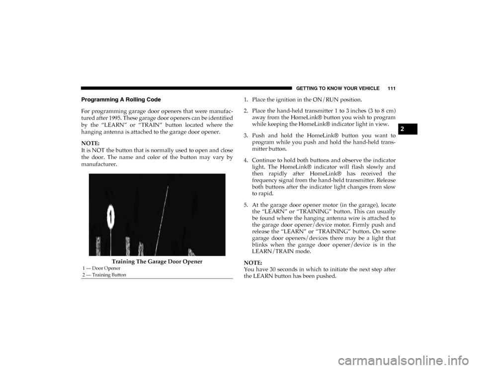
manufacturer.
Training The Garage Door Opener 1. Place the ignition in the ON/RUN position.
2. Place the hand-held transmitter 1 to 3 inches (3 to 8 cm)
away from the HomeLink® button you wish to program
while keeping the HomeLink® indicator light in view.
3. Push and hold the HomeLink® button you want to program while you push and hold the hand-held trans-
mitter button.
4. Continue to hold both buttons and observe the indicator light. The HomeLink® indicator will flash slowly and
then rapidly after HomeLink® has received the
frequency signal from the hand-held transmitter. Release
both buttons after the indicator light changes from slow
to rapid.
5. At the garage door opener motor (in the garage), locate the “LEARN” or “TRAINING” button. This can usually
be found where the hanging antenna wire is attached to
the garage door opener/device motor. Firmly push and
release the “LEARN” or “TRAINING” button. On some
garage door openers/devices there may be a light that
blinks when the garage door opener/device is in the
LEARN/TRAIN mode.
NOTE:
You have 30 seconds in which to initiate the next step after
the LEARN button has been pushed.
1 — Door Opener
2 — Training Button
2
2020_DT_1500_OM_US.book Page 111
Page 148 of 674
146 GETTING TO KNOW YOUR VEHICLE
Cleat Removal (Standard Box Rail)
To remove the cleats from the utility rail, slide the cleat
forward to access the cut out at the end of the box rail, then
remove the cleat.
Cleat Removal (With Tonneau Cover)
To remove the cleats from the utility rail, remove the end cap
screw located in the center of the end cap, using a #T30 Torx
head driver. Remove the end cap and slide the cleat off the
end of the rail.
Cleat Removal (Without Tonneau Cover)
To remove the cleats from the utility rail, depress the clip at
the bottom of the rear end cap and slide the cap off of the rail.
Once the cap is removed, slide the cleat out.Utility Rail End Cap
SLIDE-IN CAMPERS
Camper Applications
Certain truck models are not recommended for slide-in
campers. To determine if your vehicle is excluded, please
refer to the “Consumer Information Truck-Camper
Loading” document available online at
ramtrucks.com. For
safety reasons, follow all instructions in this important docu-
ment.
2020_DT_1500_OM_US.book Page 146
Page 190 of 674
188 GETTING TO KNOW YOUR INSTRUMENT PANEL
— Service Stop/Start System Warning Light — If
Equipped
This warning light will illuminate when the Stop/Start
system is not functioning properly and service is required.
Contact an authorized dealer for service.
— Service 4WD Warning Light — If Equipped
This warning light will illuminate to signal a fault with the 4WD
system. If the light stays on or comes on during driving, it means
that the 4WD system is not functioning properly and that
service is required. We recommend you drive to the nearest
service center and have the vehicle serviced immediately.
— Speed Control Fault Warning Light
This warning light will illuminate to indicate the Speed
Control System is not functioning properly and service is
required. Contact an authorized dealer.
Yellow Indicator Lights
— Forward Collision Warning Off Indicator Light — If
Equipped
This indicator light illuminates to indicate that Forward
Collision Warning is off. — Air Suspension Payload Protection Indicator Light
— If Equipped
This indicator light will illuminate to indicate that the
maximum payload may have been exceeded or load leveling
cannot be achieved at its current ride height. Protection
Mode will automatically be selected to “protect” the air
suspension system, air suspension adjustment is limited due
to payload.
— Trailer Merge Assist Indicator Light — If Equipped
This indicator light will illuminate to indicate when Trailer
Merge Assist has been activated.
Refer to “Blind Spot Monitoring (BSM)” in “Safety” for
further information.
— TOW/HAUL Indicator Light
This indicator light will illuminate when TOW/HAUL mode
is selected.
— Cargo Light — If Equipped
This indicator light will illuminate when the cargo light is
activated by pushing the cargo light button on the headlight
switch.
2020_DT_1500_OM_US.book Page 188
Page 194 of 674
192 GETTING TO KNOW YOUR INSTRUMENT PANEL
Refer to “Starting The Engine” in “Starting And Operating”
for further information.
NOTE:
The “Wait To Start” telltale may not illuminate if the intake
manifold temperature is warm enough.
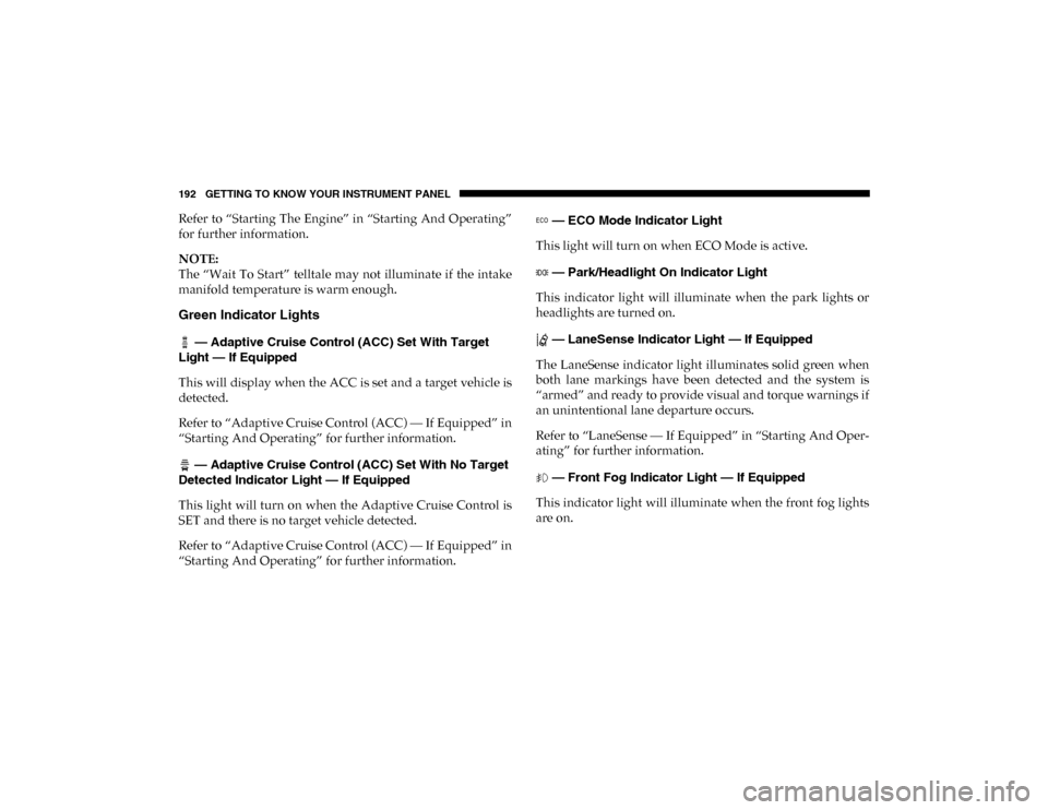
Green Indicator Lights
— Adaptive Cruise Control (ACC) Set With Target
Light — If Equipped
This will display when the ACC is set and a target vehicle is
detected.
Refer to “Adaptive Cruise Control (ACC) — If Equipped” in
“Starting And Operating” for further information.
— Adaptive Cruise Control (ACC) Set With No Target
Detected Indicator Light — If Equipped
This light will turn on when the Adaptive Cruise Control is
SET and there is no target vehicle detected.
Refer to “Adaptive Cruise Control (ACC) — If Equipped” in
“Starting And Operating” for further information. — ECO Mode Indicator Light
This light will turn on when ECO Mode is active.
— Park/Headlight On Indicator Light
This indicator light will illuminate when the park lights or
headlights are turned on.
— LaneSense Indicator Light — If Equipped
The LaneSense indicator light illuminates solid green when
both lane markings have been detected and the system is
“armed” and ready to provide visual and torque warnings if
an unintentional lane departure occurs.
Refer to “LaneSense — If Equipped” in “Starting And Oper -
ating” for further information.
— Front Fog Indicator Light — If Equipped
This indicator light will illuminate when the front fog lights
are on.
2020_DT_1500_OM_US.book Page 192
Page 201 of 674
SAFETY 199
ABS is designed to function with the Original Equipment
Manufacturer (OEM) tires. Modification may result in
degraded ABS performance.
Anti-Lock Brake Warning Light
The yellow “Anti-Lock Brake Warning Light” will turn on
when the ignition is turned to the ON/RUN mode and may
stay on for as long as four seconds.If the “Anti-Lock Brake Warning Light” remains on or comes
on while driving, it indicates that the anti-lock portion of the
brake system is not functioning and that service is required.
However, the conventional brake system will continue to
operate normally if the “Anti-Lock Brake Warning Light” is
on.
If the “Anti-Lock Brake Warning Light” is on, the brake
system should be serviced as soon as possible to restore the
benefits of anti-lock brakes. If the “Anti-Lock Brake Warning
Light” does not come on when the ignition is turned to the
ON/RUN mode, have the light repaired as soon as possible.
Electronic Brake Control System
Your vehicle is equipped with an advanced Electronic Brake
Control (EBC) system. This system includes Electronic Brake
Force Distribution (EBD), Anti-Lock Brake System (ABS),
Brake Assist System (BAS), Hill Start Assist (HSA), Traction
Control System (TCS), Electronic Stability Control (ESC),
and Electronic Roll Mitigation (ERM). These systems work
together to enhance both vehicle stability and control in
various driving conditions.
Your vehicle may also be equipped with Trailer Sway
Control (TSC) and Hill Descent Control (HDC).
• The ABS cannot prevent the natural laws of physics
from acting on the vehicle, nor can it increase braking
or steering efficiency beyond that afforded by the
condition of the vehicle brakes and tires or the traction
afforded.
• The ABS cannot prevent collisions, including those resulting from excessive speed in turns, following
another vehicle too closely, or hydroplaning.
• The capabilities of an ABS equipped vehicle must never be exploited in a reckless or dangerous manner
that could jeopardize the user’s safety or the safety of
others.
WARNING! (Continued)
4
2020_DT_1500_OM_US.book Page 199
Page 202 of 674
200 SAFETY
Brake Assist System (BAS)
The Brake Assist System (BAS) is designed to optimize the
vehicle’s braking capability during emergency braking
maneuvers. The system detects an emergency braking situa-
tion by sensing the rate and amount of brake application, and
then applies optimum pressure to the brakes. This can help
reduce braking distances. The BAS complements the
Anti-lock Brake System (ABS). Applying the brakes very
quickly results in the best BAS assistance. To receive the
benefit of the system, you must apply continuous braking
pressure during the stopping sequence, (do not “pump” the
brakes). Do not reduce brake pedal pressure unless braking
is no longer desired. Once the brake pedal is released, the
BAS is deactivated. Brake System Warning Light
The red “Brake System Warning Light” will turn on when
the ignition is turned to the ON/RUN mode and may stay on
for as long as four seconds.
If the “Brake System Warning Light” remains on or comes on
while driving, it indicates that the brake system is not func
-
tioning properly and that immediate service is required. If
the “Brake System Warning Light” does not come on when
the ignition is turned to the ON/RUN mode, have the light
repaired as soon as possible.
Electronic Brake Force Distribution (EBD)
This function manages the distribution of the braking torque
between the front and rear axles by limiting braking pressure
to the rear axle. This is done to prevent overslip of the rear
wheels to avoid vehicle instability, and to prevent the rear
axle from entering ABS before the front axle.
Electronic Roll Mitigation (ERM)
The Electronic Roll Mitigation (ERM) system anticipates the
potential for wheel lift by monitoring the driver’s steering
wheel input and the speed of the vehicle. When ERM deter -
mines that the rate of change of the steering wheel angle and
vehicle’s speed are sufficient to potentially cause wheel lift,
WARNING!
The Brake Assist System (BAS) cannot prevent the
natural laws of physics from acting on the vehicle, nor
can it increase the traction afforded by prevailing road
conditions. BAS cannot prevent collisions, including
those resulting from excessive speed in turns, driving on
very slippery surfaces, or hydroplaning. The capabilities
of a BAS-equipped vehicle must never be exploited in a
reckless or dangerous manner, which could jeopardize
the user's safety or the safety of others.
2020_DT_1500_OM_US.book Page 200
Page 203 of 674
SAFETY 201
it then applies the appropriate brake and may also reduce
engine power to lessen the chance that wheel lift will occur.
ERM can only reduce the chance of wheel lift occurring
during severe or evasive driving maneuvers; it cannot
prevent wheel lift due to other factors, such as road condi-
tions, leaving the roadway, or striking objects or other vehi -
cles.
NOTE:
ERM is disabled anytime the ESC is in “Full Off” mode (if
equipped). Refer to “Electronic Stability Control (ESC)” in
this section for a complete explanation of the available ESC
modes. Electronic Stability Control (ESC)
The Electronic Stability Control (ESC) system enhances
directional control and stability of the vehicle under various
driving conditions. ESC corrects for oversteering or under
-
steering of the vehicle by applying the brake of the appro -
priate wheel(s) to assist in counteracting the oversteer or
understeer condition. Engine power may also be reduced to
help the vehicle maintain the desired path.
ESC uses sensors in the vehicle to determine the vehicle path
intended by the driver and compares it to the actual path of
the vehicle. When the actual path does not match the
intended path, ESC applies the brake of the appropriate
wheel to assist in counteracting the oversteer or understeer
condition.
• Oversteer — when the vehicle is turning more than appro -
priate for the steering wheel position.
• Understeer — when the vehicle is turning less than appro -
priate for the steering wheel position.
The “ESC Activation/Malfunction Indicator Light” located
in the instrument cluster will start to flash as soon as the ESC
system becomes active. The “ESC Activation/Malfunction
Indicator Light” also flashes when the TCS is active. If the
“ESC Activation/Malfunction Indicator Light” begins to
WARNING!
Many factors, such as vehicle loading, road conditions
and driving conditions, influence the chance that wheel
lift or rollover may occur. ERM cannot prevent all wheel
lift or roll overs, especially those that involve leaving the
roadway or striking objects or other vehicles. The
capabilities of an ERM-equipped vehicle must never be
exploited in a reckless or dangerous manner which could
jeopardize the user's safety or the safety of others.
4
2020_DT_1500_OM_US.book Page 201
Page 205 of 674

SAFETY 203
ESC Operating Modes
NOTE:
Depending upon model and mode of operation, the ESC
system may have multiple operating modes.
ESC On
This is the normal operating mode for the ESC. Whenever
the vehicle is started, the ESC system will be in this mode.
This mode should be used for most driving conditions. Alter-
nate ESC modes should only be used for specific reasons as
noted in the following paragraphs.
Partial Off
The “Partial Off” mode is intended for times when a more
spirited driving experience is desired. This mode may
modify TCS and ESC thresholds for activation, which allows
for more wheel spin than normally allowed. This mode may
be useful if the vehicle becomes stuck.
To enter the “Partial Off” mode, momentarily push the “ESC
Off” switch and the “ESC Off Indicator Light” will illumi -
nate. To turn the ESC on again, momentarily push the “ESC
Off” switch and the “ESC Off Indicator Light” will turn off. NOTE:
For vehicles with multiple partial ESC modes a momentary
button push will toggle the ESC mode. Multiple momentary
button pushed may be required to return to ESC On.
Full Off — If Equipped
This mode is intended for off-highway or off-road use only
and should not be used on any public roadways. In this
mode, TCS and ESC features are turned OFF. To enter the
“Full Off” mode, push and hold the “ESC Off” switch for five
seconds while the vehicle is stopped with the engine
running. After five seconds, a chime will sound, the “ESC Off
WARNING!
• When in “Partial Off” mode, the TCS functionality of ESC, (except for the limited slip feature described in
the TCS section), has been disabled and the “ESC Off
Indicator Light” will be illuminated. When in “Partial
Off” mode, the engine power reduction feature of TCS
is disabled, and the enhanced vehicle stability offered
by the ESC system is reduced.
• Trailer Sway control (TSC) is disabled when the ESC system is in the “Partial Off” mode.
4
2020_DT_1500_OM_US.book Page 203