change wheel Ram 1500 2020 Owner's Manual
[x] Cancel search | Manufacturer: RAM, Model Year: 2020, Model line: 1500, Model: Ram 1500 2020Pages: 674, PDF Size: 32.69 MB
Page 5 of 674

3
Ventilated Seats — If Equipped .................................. 52
Plastic Grocery Bag Retainers ..................................... 54
HEAD RESTRAINTS ......................................................... 54
Front Head Restraints ................................................... 54
Rear Head Restraints .................................................... 55
STEERING WHEEL ............................................................ 56
Tilt/Telescoping Steering Column ............................. 56
Heated Steering Wheel — If Equipped ..................... 57
DRIVER ADJUSTABLE PEDALS — IF EQUIPPED ...... 58
MIRRORS ............................................................................ 59
Inside Day/Night Mirror — If Equipped ................. 59
Automatic Dimming Mirror — If Equipped ............ 60
Outside Mirrors ............................................................ 61
Driver's Outside Automatic Dimming Mirror — If
Equipped......................................................................... 61
Power Mirrors — If Equipped .................................... 61
Power Folding Outside Mirrors For Standard And
Trailer Tow — If Equipped .......................................... 62
Trailer Towing Mirrors — If Equipped ..................... 64
Heated Mirrors — If Equipped ................................... 65
Tilt Side Mirrors In Reverse — If Equipped .............. 65
Illuminated Vanity Mirror — If Equipped ................ 65
EXTERIOR LIGHTS ............................................................ 66
Headlight Switch ........................................................... 66
Daytime Running Lights (DRLs) — If Equipped ..... 67
Multifunction Lever .....................................................68
High/Low Beam Switch ...............................................68
Automatic High Beam Headlamp Control — If
Equipped ........................................................................68
Flash-To-Pass..................................................................69
Automatic Headlights — If Equipped........................70
Parking Lights And Panel Lights ................................70
Headlights On With Wipers (Available With
Automatic Headlights Only)........................................70
Headlight Delay .............................................................70
Lights-On Reminder......................................................71
Front Fog Lights — If Equipped .................................71
Turn Signals ...................................................................71
Lane Change Assist — If Equipped ............................71
Cargo Light With Bed Lights — If Equipped ............72
Battery Saver...................................................................73
INTERIOR LIGHTS ............................................................73
Courtesy Lights ..............................................................73
Illuminated Entry ..........................................................75
WINDSHIELD WIPERS AND WASHERS ......................75
Windshield Wipers........................................................75
Rain Sensing Wipers — If Equipped ..........................77
CLIMATE CONTROLS .....................................................78
Manual Climate Control Overview ............................78
Automatic Climate Control Overview .......................82
2020_DT_1500_OM_US.book Page 3
Page 73 of 674
GETTING TO KNOW YOUR VEHICLE 71
Lights-On Reminder
If the headlights, parking lights, or cargo lights are left on
after the ignition is placed in the OFF position, a chime will
sound when the driver’s door is opened.
Front Fog Lights — If Equipped
To activate the front fog lights, turn on the parking lights or
low beam headlights and push in the center of the headlight
switch control knob. Pushing the headlight switch control
knob a second time will turn the front fog lights off.Front Fog Light Switch If the fog lights are off, one of the fog lights will illuminate
depending on the direction in which the vehicle is turning.
This will provide increased visibility while turning,
depending on the angle of the steering wheel.
Turn Signals
Move the multifunction lever up or down and the arrows on
each side of the instrument cluster display will flash to show
proper operation of the front and rear turn signal lights.
NOTE:
If either light remains on and does not flash, or there is a very
fast flash rate, check for a defective outside light bulb. If an
indicator fails to light when the lever is moved, it would
suggest that the indicator bulb is defective.
Lane Change Assist — If Equipped
Tap the multifunction lever up or down once, without
moving beyond the detent, and the turn signal (right or left)
will flash three times then automatically turn off.
2
2020_DT_1500_OM_US.book Page 71
Page 82 of 674
80 GETTING TO KNOW YOUR VEHICLE
Blower Control
There are seven blower speeds. Use this control knob to regulate the amount of air forced through the
system in any mode you select. The blower speed increases as you move the control clockwise from
the off position.
Modes Control
Rotate the Mode Control Knob to change the airflow distribution mode. The airflow distribution mode
can be adjusted so air comes from the instrument panel outlets, floor outlets, defrost outlets and
demist outlets. The Mode settings are as follows:
Panel Mode Panel Mode
Air comes from the outlets in the instrument panel. Each of these outlets can be individually adjusted
to direct the flow of air. The air vanes of the center outlets and outboard outlets can be moved up and
down or side to side to regulate airflow direction. There is a shut off wheel located below the air vanes
to shut off or adjust the amount of airflow from these outlets.
Bi-Level Mode Bi-Level Mode
Air comes from the instrument panel outlets and floor outlets. A slight amount of air is directed
through the defrost and side window demister outlets.
NOTE:
Bi-Level mode is designed under comfort conditions to provide cooler air out of the panel outlets and
warmer air from the floor outlets.
Icon
Description
2020_DT_1500_OM_US.book Page 80
Page 91 of 674
GETTING TO KNOW YOUR VEHICLE 89
Faceplate Mode Button
Touchscreen Mode Buttons Modes Control
•
Faceplate: Push the Mode Button to change the airflow distribution mode. The airflow distribution
mode can be adjusted so air comes from the instrument panel outlets, floor outlets, defrost outlets and
demist outlets.
• Touchscreen: Press one of the “MODE” buttons to change the airflow distribution mode. The airflow
distribution mode can be adjusted so air comes from the instrument panel outlets, floor outlets,
defrost outlets and demist outlets.
The Mode settings are as follows:
Panel Mode Panel Mode
Air comes from the outlets in the instrument panel. Each of these outlets can be individually adjusted
to direct the flow of air. The air vanes of the center outlets and outboard outlets can be moved up and
down or side to side to regulate airflow direction. There is a shut off wheel located below the air vanes
to shut off or adjust the amount of airflow from these outlets.
Bi-Level Mode Bi-Level Mode
Air comes from the instrument panel outlets and floor outlets. A slight amount of air is directed
through the defrost and side window demister outlets.
NOTE:
Bi-Level mode is designed under comfort conditions to provide cooler air out of the panel outlets and
warmer air from the floor outlets.
Icon
Description
2
2020_DT_1500_OM_US.book Page 89
Page 172 of 674

170 GETTING TO KNOW YOUR INSTRUMENT PANEL
Driver Assist — If Equipped
The Driver Assist menu displays the status of the ACC and
LaneSense systems.
Push and release the up or down arrow button until the
Driver Assist menu is displayed in the instrument cluster
display.
Adaptive Cruise Control (ACC) Feature
The instrument cluster display displays the current Adap -
tive Cruise Control (ACC) system settings. The information
displayed depends on ACC system status.
Push the Adaptive Cruise Control (ACC) on/off button
(located on the steering wheel) until one of the following
displays in the instrument cluster display:
Adaptive Cruise Control Off
When ACC is deactivated, the display will read “Adaptive
Cruise Control Off.”
Adaptive Cruise Control Ready
When ACC is activated but the vehicle speed setting has not
been selected, the display will read “Adaptive Cruise
Control Ready.” Push the SET + or the SET- button (located on the steering
wheel) and the following will display in the instrument
cluster display:
ACC SET
When ACC is set, the set speed will display in the instrument
cluster.
The ACC screen may display once again if any ACC activity
occurs, which may include any of the following:
• Distance Setting Change
• System Cancel
• Driver Override
• System Off
• ACC Proximity Warning
• ACC Unavailable Warning
For further information, refer to “Adaptive Cruise Control
(ACC) — If Equipped” in “Starting And Operating.”
2020_DT_1500_OM_US.book Page 170
Page 202 of 674

200 SAFETY
Brake Assist System (BAS)
The Brake Assist System (BAS) is designed to optimize the
vehicle’s braking capability during emergency braking
maneuvers. The system detects an emergency braking situa-
tion by sensing the rate and amount of brake application, and
then applies optimum pressure to the brakes. This can help
reduce braking distances. The BAS complements the
Anti-lock Brake System (ABS). Applying the brakes very
quickly results in the best BAS assistance. To receive the
benefit of the system, you must apply continuous braking
pressure during the stopping sequence, (do not “pump” the
brakes). Do not reduce brake pedal pressure unless braking
is no longer desired. Once the brake pedal is released, the
BAS is deactivated. Brake System Warning Light
The red “Brake System Warning Light” will turn on when
the ignition is turned to the ON/RUN mode and may stay on
for as long as four seconds.
If the “Brake System Warning Light” remains on or comes on
while driving, it indicates that the brake system is not func
-
tioning properly and that immediate service is required. If
the “Brake System Warning Light” does not come on when
the ignition is turned to the ON/RUN mode, have the light
repaired as soon as possible.
Electronic Brake Force Distribution (EBD)
This function manages the distribution of the braking torque
between the front and rear axles by limiting braking pressure
to the rear axle. This is done to prevent overslip of the rear
wheels to avoid vehicle instability, and to prevent the rear
axle from entering ABS before the front axle.
Electronic Roll Mitigation (ERM)
The Electronic Roll Mitigation (ERM) system anticipates the
potential for wheel lift by monitoring the driver’s steering
wheel input and the speed of the vehicle. When ERM deter -
mines that the rate of change of the steering wheel angle and
vehicle’s speed are sufficient to potentially cause wheel lift,
WARNING!
The Brake Assist System (BAS) cannot prevent the
natural laws of physics from acting on the vehicle, nor
can it increase the traction afforded by prevailing road
conditions. BAS cannot prevent collisions, including
those resulting from excessive speed in turns, driving on
very slippery surfaces, or hydroplaning. The capabilities
of a BAS-equipped vehicle must never be exploited in a
reckless or dangerous manner, which could jeopardize
the user's safety or the safety of others.
2020_DT_1500_OM_US.book Page 200
Page 204 of 674

202 SAFETY
(Continued)
flash during acceleration, ease up on the accelerator and
apply as little throttle as possible. Be sure to adapt your
speed and driving to the prevailing road conditions.
WARNING!
• Electronic Stability Control (ESC) cannot prevent the natural laws of physics from acting on the vehicle, nor
can it increase the traction afforded by prevailing road
conditions. ESC cannot prevent accidents, including
those resulting from excessive speed in turns, driving
on very slippery surfaces, or hydroplaning. ESC also
cannot prevent accidents resulting from loss of vehicle
control due to inappropriate driver input for the condi -
tions. Only a safe, attentive, and skillful driver can
prevent accidents. The capabilities of an ESC equipped
vehicle must never be exploited in a reckless or
dangerous manner which could jeopardize the user’s
safety or the safety of others.
• Vehicle modifications, or failure to properly maintain your vehicle, may change the handling characteristics
of your vehicle, and may negatively affect the perfor -
mance of the ESC system. Changes to the steering
system, suspension, braking system, tire type and size
or wheel size may adversely affect ESC performance.
Improperly inflated and unevenly worn tires may also
degrade ESC performance. Any vehicle modification or
poor vehicle maintenance that reduces the effective -
ness of the ESC system can increase the risk of loss of
vehicle control, vehicle rollover, personal injury and
death.
WARNING! (Continued)
2020_DT_1500_OM_US.book Page 202
Page 211 of 674

SAFETY 209
Towing With HSA
Hill Start Assist (HSA) will also provide assistance to miti-
gate roll back while towing a trailer. Disabling And Enabling HSA
This feature can be turned on or turned off. To change the
current setting, proceed as follows:
• If disabling HSA using your instrument cluster display,
refer to “Instrument Cluster Display” in “Getting To Know
Your Instrument Panel” for further information.
• If disabling HSA using Uconnect Settings, refer to “Ucon -
nect Settings” in “Multimedia” for further information.
For vehicles not equipped with an instrument cluster
display, perform the following steps:
1. Center the steering wheel (front wheels pointing straight forward).
2. Shift the transmission into PARK (P).
3. Apply the park brake.
4. Start the engine.
5. Rotate the steering wheel slightly more than one-half turn to the left.
WARNING!
• If you use a trailer brake controller with your trailer, the trailer brakes may be activated and deactivated with
the brake switch. If so, there may not be enough brake
pressure to hold both the vehicle and the trailer on a
hill when the brake pedal is released. In order to avoid
rolling down an incline while resuming acceleration,
manually activate the trailer brake or apply more
vehicle brake pressure prior to releasing the brake
pedal.
• HSA is not a parking brake. Always apply the parking brake fully when exiting your vehicle. Also, be certain
to place the transmission in PARK.
• Failure to follow these warnings can result in a colli -
sion or serious personal injury.
4
2020_DT_1500_OM_US.book Page 209
Page 221 of 674
SAFETY 219
The vehicle must be moving above 6 mph (10 km/h) to
activate the feature. Once the trailer has been detected, the
system will default to the maximum blind spot zone until
the length has been verified. You will see “Auto” in the
instrument panel cluster .
• Max Mode — When “Max Mode” is selected, the system
will default to the maximum blind spot zone regardless of
what size trailer is attached
NOTE:
Selected setting is stored when the ignition is cycled OFF. To
change this setting, it must be selected through the Uconnect
Settings. Refer to “Uconnect Settings” in “Multimedia” for
further information.
Trailer Length Detection
Once the trailer presence has been established. The trailer
length will be established (by making a 90 degree turn) and
then the trailer length category (example 10-20 ft (3 m to
6 m)) will be displayed. This can take up to 30 seconds after
completing the turn. NOTE:
During the same ignition cycle, if the vehicle is at a standstill
for a minimum of 90 seconds, a new “trailer detection
request” is enabled by the system once the vehicle resumes
motion.
Maximum length supported by the Trailer Merge Assist
feature is 39.5 ft (12 m). Trailer length is considered the
forward most portion of the trailer hitch to the rearward
most portion of the body, bumper, or ramp of the trailer.
Maximum width supported by the Trailer Merge Assist
feature is 8.5 ft (2.59 m). Trailer width is measured at the
widest portion of the trailer and may include wheels, tires,
finders, or rails.
NOTE:
Fifth wheel or gooseneck trailers are not supported by
Trailer Merge Assist.
4
2020_DT_1500_OM_US.book Page 219
Page 231 of 674
SAFETY 229
• The TPMS is not a substitute for proper tire maintenance,and it is the driver’s responsibility to maintain correct tire
pressure using an accurate tire pressure gauge, even if
under-inflation has not reached the level to trigger illumi -
nation of the TPMS Warning Light.
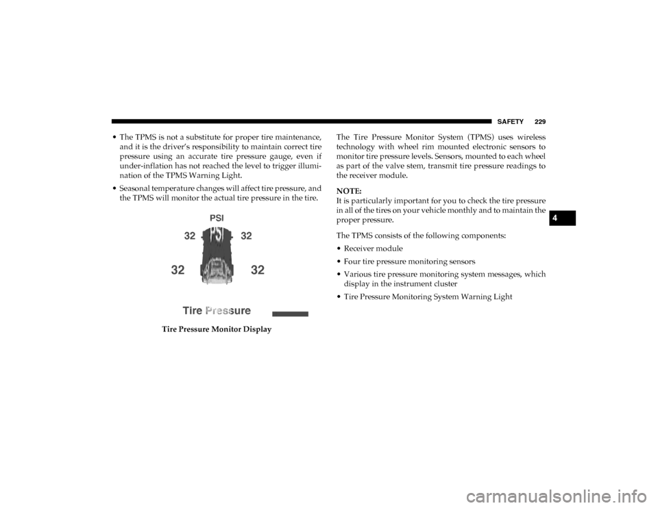
• Seasonal temperature changes will affect tire pressure, and the TPMS will monitor the actual tire pressure in the tire.
Tire Pressure Monitor Display The Tire Pressure Monitor System (TPMS) uses wireless
technology with wheel rim mounted electronic sensors to
monitor tire pressure levels. Sensors, mounted to each wheel
as part of the valve stem, transmit tire pressure readings to
the receiver module.
NOTE:
It is particularly important for you to check the tire pressure
in all of the tires on your vehicle monthly and to maintain the
proper pressure.
The TPMS consists of the following components:
• Receiver module
• Four tire pressure monitoring sensors
• Various tire pressure monitoring system messages, which
display in the instrument cluster
• Tire Pressure Monitoring System Warning Light
4
2020_DT_1500_OM_US.book Page 229