wheel sensor Ram 1500 2020 Owner's Manual
[x] Cancel search | Manufacturer: RAM, Model Year: 2020, Model line: 1500, Model: Ram 1500 2020Pages: 674, PDF Size: 32.69 MB
Page 189 of 674
GETTING TO KNOW YOUR INSTRUMENT PANEL 187
tires or wheels on your vehicle to ensure that the replace-
ment or alternate tires and wheels allow the TPMS to
continue to function properly.
— Anti-Lock Brake (ABS) Warning Light
This warning light monitors the Anti-Lock Brake System
(ABS). The light will turn on when the ignition is placed in
the ON/RUN or ACC/ON/RUN position and may stay on
for as long as four seconds. If the ABS light remains on or turns on while driving, then
the Anti-Lock portion of the brake system is not functioning
and service is required as soon as possible. However, the
conventional brake system will continue to operate
normally, assuming the Brake Warning Light is not also on.
If the ABS light does not turn on when the ignition is placed
in the ON/RUN or ACC/ON/RUN position, have the brake
system inspected by an authorized dealer.
— Rear Axle Locker Fault Indicator Light — If
Equipped
This warning light will illuminate to indicate when a rear
axle locker fault has been detected.
— Service Forward Collision Warning (FCW) Light —
If Equipped
This warning light will illuminate to indicate a fault in the
Forward Collision Warning System. Contact an authorized
dealer for service.
Refer to “Forward Collision Warning (FCW) With Mitiga -
tion” in “Safety” for further information.
CAUTION!
The TPMS has been optimized for the original
equipment tires and wheels. TPMS pressures and
warning have been established for the tire size equipped
on your vehicle. Undesirable system operation or sensor
damage may result when using replacement equipment
that is not of the same size, type, and/or style.
Aftermarket wheels can cause sensor damage. Using
aftermarket tire sealants may cause the Tire Pressure
Monitoring System (TPMS) sensor to become
inoperable. After using an aftermarket tire sealant it is
recommended that you take your vehicle to your
authorized dealer to have your sensor function checked.
3
2020_DT_1500_OM_US.book Page 187
Page 203 of 674
SAFETY 201
it then applies the appropriate brake and may also reduce
engine power to lessen the chance that wheel lift will occur.
ERM can only reduce the chance of wheel lift occurring
during severe or evasive driving maneuvers; it cannot
prevent wheel lift due to other factors, such as road condi-
tions, leaving the roadway, or striking objects or other vehi -
cles.
NOTE:
ERM is disabled anytime the ESC is in “Full Off” mode (if
equipped). Refer to “Electronic Stability Control (ESC)” in
this section for a complete explanation of the available ESC
modes. Electronic Stability Control (ESC)
The Electronic Stability Control (ESC) system enhances
directional control and stability of the vehicle under various
driving conditions. ESC corrects for oversteering or under
-
steering of the vehicle by applying the brake of the appro -
priate wheel(s) to assist in counteracting the oversteer or
understeer condition. Engine power may also be reduced to
help the vehicle maintain the desired path.
ESC uses sensors in the vehicle to determine the vehicle path
intended by the driver and compares it to the actual path of
the vehicle. When the actual path does not match the
intended path, ESC applies the brake of the appropriate
wheel to assist in counteracting the oversteer or understeer
condition.
• Oversteer — when the vehicle is turning more than appro -
priate for the steering wheel position.
• Understeer — when the vehicle is turning less than appro -
priate for the steering wheel position.
The “ESC Activation/Malfunction Indicator Light” located
in the instrument cluster will start to flash as soon as the ESC
system becomes active. The “ESC Activation/Malfunction
Indicator Light” also flashes when the TCS is active. If the
“ESC Activation/Malfunction Indicator Light” begins to
WARNING!
Many factors, such as vehicle loading, road conditions
and driving conditions, influence the chance that wheel
lift or rollover may occur. ERM cannot prevent all wheel
lift or roll overs, especially those that involve leaving the
roadway or striking objects or other vehicles. The
capabilities of an ERM-equipped vehicle must never be
exploited in a reckless or dangerous manner which could
jeopardize the user's safety or the safety of others.
4
2020_DT_1500_OM_US.book Page 201
Page 212 of 674
210 SAFETY
6. Push the “ESC Off” button located in the lower switch bankbelow the climate control four times within 20 seconds. The
“ESC Off Indicator Light” should turn on and turn off two
times.
7. Rotate the steering wheel back to center and then an addi -
tional slightly more than one-half turn to the right.
8. Turn the ignition to the OFF mode and then back to ON. If the sequence was completed properly, the “ESC Off
Indicator Light” will blink several times to confirm HSA
is disabled.
9. Repeat these steps if you want to return this feature to its previous setting.
Traction Control System (TCS)
The Traction Control System (TCS) monitors the amount of
wheel spin of each of the driven wheels. If wheel spin is
detected, the TCS may apply brake pressure to the spinning
wheel(s) and/or reduce engine power to provide enhanced
acceleration and stability. A feature of the TCS, Brake
Limited Differential (BLD), functions similar to a limited slip
differential and controls the wheel spin across a driven axle.
If one wheel on a driven axle is spinning faster than the other,
the system will apply the brake of the spinning wheel. This will allow more engine torque to be applied to the wheel that
is not spinning. BLD may remain enabled even if TCS and
ESC are in a reduced mode.
Trailer Sway Control (TSC)
Trailer Sway Control (TSC) uses sensors in the vehicle to
recognize an excessively swaying trailer and will take the
appropriate actions to attempt to stop the sway. TSC will
become active automatically once an excessively swaying
trailer is recognized.
NOTE:
TSC cannot stop all trailers from swaying. Always use
caution when towing a trailer and follow the trailer tongue
weight recommendations. Refer to “Trailer Towing” in
“Starting And Operating” for further information.
When TSC is functioning, the “ESC Activation/Malfunction
Indicator Light” will flash, the engine power may be reduced
and you may feel the brakes being applied to individual
wheels to attempt to stop the trailer from swaying. TSC is
disabled when the ESC system is in the “Partial Off” or “Full
Off” modes.
WARNING!
If TSC activates while driving, slow the vehicle down,
stop at the nearest safe location, and adjust the trailer
load to eliminate trailer sway.
2020_DT_1500_OM_US.book Page 210
Page 230 of 674

228 SAFETY
(Continued)
NOTE:
When filling warm tires, the tire pressure may need to be
increased up to an additional 4 psi (28 kPa) above the recom-
mended cold placard pressure in order to turn the TPMS
Warning Light off.
For example, your vehicle may have a recommended cold
(parked for more than three hours) placard pressure of 30 psi
(207 kPa). If the ambient temperature is 68°F (20°C) and the
measured tire pressure is 27 psi (186 kPa), a temperature
drop to 20°F (-7°C) will decrease the tire pressure to approx -
imately 23 psi (158 kPa). This tire pressure is sufficiently low
enough to turn on the TPMS Warning Light. Driving the
vehicle may cause the tire pressure to rise to approximately
27 psi (186 kPa), but the TPMS Warning Light will still be on.
In this situation, the TPMS Warning Light will turn off only
after the tires are inflated to the vehicle’s recommended cold
placard pressure value. NOTE:
• The TPMS is not intended to replace normal tire care and
maintenance or to provide warning of a tire failure or
condition.
• The TPMS should not be used as a tire pressure gauge while adjusting your tire pressure.
• Driving on a significantly under-inflated tire causes the tire to overheat and can lead to tire failure. Under-inflation
also reduces fuel efficiency and tire tread life, and may
affect the vehicle’s handling and stopping ability.
CAUTION!
• The TPMS has been optimized for the original equip -
ment tires and wheels. TPMS pressures and warning
have been established for the tire size equipped on
your vehicle. Undesirable system operation or sensor
damage may result when using replacement equipment
that is not of the same size, type, and/or style. After -
market wheels can cause sensor damage.
• Using aftermarket tire sealants may cause the Tire Pres -
sure Monitoring System (TPMS) sensor to become
inoperable. After using an aftermarket tire sealant it is
recommended that you take your vehicle to an autho -
rized dealership to have your sensor function checked.
• After inspecting or adjusting the tire pressure always reinstall the valve stem cap. This will prevent moisture
and dirt from entering the valve stem, which could
damage the TPMS sensor. CAUTION!
(Continued)
2020_DT_1500_OM_US.book Page 228
Page 231 of 674
SAFETY 229
• The TPMS is not a substitute for proper tire maintenance,and it is the driver’s responsibility to maintain correct tire
pressure using an accurate tire pressure gauge, even if
under-inflation has not reached the level to trigger illumi -
nation of the TPMS Warning Light.
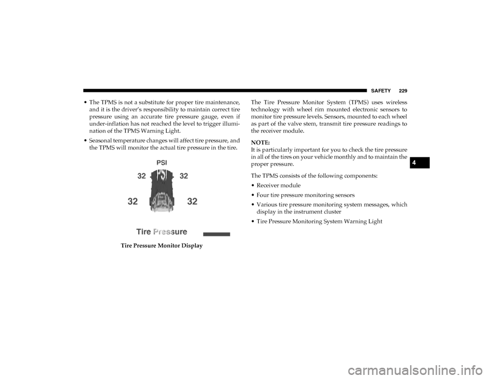
• Seasonal temperature changes will affect tire pressure, and the TPMS will monitor the actual tire pressure in the tire.
Tire Pressure Monitor Display The Tire Pressure Monitor System (TPMS) uses wireless
technology with wheel rim mounted electronic sensors to
monitor tire pressure levels. Sensors, mounted to each wheel
as part of the valve stem, transmit tire pressure readings to
the receiver module.
NOTE:
It is particularly important for you to check the tire pressure
in all of the tires on your vehicle monthly and to maintain the
proper pressure.
The TPMS consists of the following components:
• Receiver module
• Four tire pressure monitoring sensors
• Various tire pressure monitoring system messages, which
display in the instrument cluster
• Tire Pressure Monitoring System Warning Light
4
2020_DT_1500_OM_US.book Page 229
Page 233 of 674

SAFETY 231
If the ignition switch is cycled, this sequence will repeat,
providing the system fault still exists. If the system fault no
longer exists, the “Tire Pressure Monitoring System Warning
Light” will no longer flash, and the "SERVICE TPM
SYSTEM" message will no longer display, and a pressure
value will display in place of the dashes. A system fault can
occur due to any of the following:
• Signal interference due to electronic devices or drivingnext to facilities emitting the same radio frequencies as the
Tire Pressure Monitor (TPM) sensors
• Installing aftermarket window tinting that contains mate -
rials that may block radio wave signals
• Accumulation of snow or ice around the wheels or wheel housings
• Using tire chains on the vehicle
• Using wheels/tires not equipped with TPM sensors
A system fault may occur due to an incorrect TPM sensor loca -
tion condition. When a system fault occurs due to an incorrect
TPM sensor location, the “Tire Pressure Monitoring System
(TPMS) Warning Light” will flash on and off for 75 seconds
and then remain on solid. The system fault will also sound a
chime. In addition, the instrument cluster will display a “Tire
Pressure Temporarily Unavailable” message in place of the
tire pressure display screen. If the ignition switch is cycled, this sequence will repeat, providing the system fault still
exists. If the system fault no longer exists, the “Tire Pressure
Monitoring System Warning Light” will no longer flash and
the tire pressure display screen will be displayed showing the
tire pressure values the correct locations.
Vehicles With Non Matching Full Size Spare Or Compact
Spare
• The non matching full size spare or compact spare tire
does not have a TPM sensor. Therefore, the TPMS will not
monitor the pressure in the non matching full size spare or
compact spare tire.
• If you install the non matching full size spare or compact spare tire in place of a road tire that has a pressure below
the low-pressure warning limit, upon the next ignition
switch cycle, the Tire Pressure Monitoring System (TPMS)
Warning Light and a “LOW TIRE” message will remain
ON and a chime will sound. In addition, the graphic in the
instrument cluster will still display a pressure value in a
different color and an “Inflate to XX” message.
• After driving the vehicle for up to 20 minutes above 15 mph (24 km/h), the Tire Pressure Monitoring System
(TPMS) Warning Light will flash on and off for 75 seconds
and then remain on solid. In addition, the instrument
4
2020_DT_1500_OM_US.book Page 231
Page 248 of 674
246 SAFETY
The air bag system must be ready to protect you in a colli-
sion. The Occupant Restraint Controller (ORC) monitors the
internal circuits and interconnecting wiring associated with
the electrical Air Bag System Components. Your vehicle may
be equipped with the following Air Bag System Compo -
nents:
Air Bag System Components
• Occupant Restraint Controller (ORC)
• Air Bag Warning Light
• Steering Wheel and Column
• Instrument Panel
• Knee Impact Bolsters
• Driver and Front Passenger Air Bags
• Seat Belt Buckle Switch
• Supplemental Side Air Bags
• Front and Side Impact Sensors
• Seat Belt Pretensioners
• Seat Track Position Sensors
• Occupant Classification System Air Bag Warning Light
The ORC monitors the readiness of the electronic
parts of the air bag system whenever the ignition
switch is in the START or ON/RUN position. If the
ignition switch is in the OFF position or in the ACC position,
the air bag system is not on and the air bags will not inflate.
The ORC contains a backup power supply system that may
deploy the air bag system even if the battery loses power or
it becomes disconnected prior to deployment.
The ORC turns on the Air Bag Warning Light in the instru-
ment panel for approximately four to eight seconds for a
self-check when the ignition switch is first in the ON/RUN
position. After the self-check, the Air Bag Warning Light will
turn off. If the ORC detects a malfunction in any part of the
system, it turns on the Air Bag Warning Light, either
momentarily or continuously. A single chime will sound to
alert you if the light comes on again after initial startup.
The ORC also includes diagnostics that will illuminate the
instrument panel Air Bag Warning Light if a malfunction is
detected that could affect the air bag system. The diagnostics
also record the nature of the malfunction. While the air bag
2020_DT_1500_OM_US.book Page 246
Page 250 of 674
248 SAFETY
(Continued)
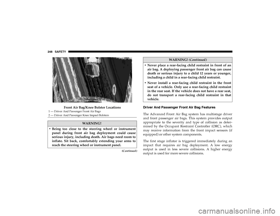
Front Air Bag/Knee Bolster LocationsDriver And Passenger Front Air Bag Features
The Advanced Front Air Bag system has multistage driver
and front passenger air bags. This system provides output
appropriate to the severity and type of collision as deter
-
mined by the Occupant Restraint Controller (ORC), which
may receive information from the front impact sensors (if
equipped) or other system components.
The first stage inflator is triggered immediately during an
impact that requires air bag deployment. A low energy
output is used in less severe collisions. A higher energy
output is used for more severe collisions.
1 — Driver And Passenger Front Air Bags
2 — Driver And Passenger Knee Impact Bolsters
WARNING!
• Being too close to the steering wheel or instrument panel during front air bag deployment could cause
serious injury, including death. Air bags need room to
inflate. Sit back, comfortably extending your arms to
reach the steering wheel or instrument panel.
• Never place a rear-facing child restraint in front of anair bag. A deploying passenger front air bag can cause
death or serious injury to a child 12 years or younger,
including a child in a rear-facing child restraint.
• Never install a rear-facing child restraint in the front seat of a vehicle. Only use a rear-facing child restraint
in the rear seat. If the vehicle does not have a rear seat,
do not transport a rear-facing child restraint in that
vehicle.
WARNING! (Continued)
2020_DT_1500_OM_US.book Page 248
Page 251 of 674

SAFETY 249
(Continued)
This vehicle may be equipped with a driver and/or front
passenger seat belt buckle switch that detects whether the
driver or front passenger seat belt is buckled. The seat belt
buckle switch may adjust the inflation rate of the Advanced
Front Air Bags.
This vehicle may be equipped with driver and/or front
passenger seat track position sensors that may adjust the
inflation rate of the Advanced Front Air Bags based upon
seat position.
This vehicle is equipped with a right front passenger Occu-
pant Classification System (“OCS”) that is designed to
provide Passenger Advanced Front Air Bag output appro-
priate to the occupant’s seated weight input, as determined
by the OCS. Front Air Bag Operation
Front Air Bags are designed to provide additional protection
by supplementing the seat belts. Front air bags are not
expected to reduce the risk of injury in rear, side, or rollover
collisions. The front air bags will not deploy in all frontal
collisions, including some that may produce substantial
vehicle damage — for example, some pole collisions, truck
underrides, and angle offset collisions.
WARNING!
• No objects should be placed over or near the air bag on the instrument panel or steering wheel because any
such objects could cause harm if the vehicle is in a colli -
sion severe enough to cause the air bag to inflate.
• Do not put anything on or around the air bag covers or attempt to open them manually. You may damage the
air bags and you could be injured because the air bags
may no longer be functional. The protective covers for
the air bag cushions are designed to open only when
the air bags are inflating.
• Relying on the air bags alone could lead to more severe injuries in a collision. The air bags work with your seat
belt to restrain you properly. In some collisions, air
bags won’t deploy at all. Always wear your seat belts
even though you have air bags.
WARNING! (Continued)
4
2020_DT_1500_OM_US.book Page 249
Page 252 of 674
250 SAFETY
On the other hand, depending on the type and location of
impact, front air bags may deploy in crashes with little
vehicle front-end damage but that produce a severe initial
deceleration.
Because air bag sensors measure vehicle deceleration over
time, vehicle speed and damage by themselves are not good
indicators of whether or not an air bag should have
deployed.
Seat belts are necessary for your protection in all collisions,
and also are needed to help keep you in position, away from
an inflating air bag.
When the ORC detects a collision requiring the front air bags,
it signals the inflator units. A large quantity of non-toxic gas
is generated to inflate the front air bags.
The steering wheel hub trim cover and the upper passenger
side of the instrument panel separate and fold out of the way
as the air bags inflate to their full size. The front air bags fully
inflate in less time than it takes to blink your eyes. The front
air bags then quickly deflate while helping to restrain the
driver and front passenger.Occupant Classification System (OCS) — Front
Passenger Seat
The OCS is part of a Federally regulated safety system for
this vehicle. It is designed to provide Passenger Advanced
Front Air Bag output appropriate to the occupant’s seated
weight, as determined by the OCS.
The Occupant Classification System (OCS) consists of the
following:
• Occupant Restraint Controller (ORC)
• Occupant Classification Module (OCM) and Sensor
located in the front passenger seat
• Air Bag Warning Light
Occupant Classification Module (OCM) And Sensor
The Occupant Classification Module (OCM) is located
underneath the front passenger seat. The Sensor is located
beneath the passenger seat cushion foam. Any weight on the
seat will be sensed by the Sensor. The OCM uses input from
the Sensor to determine the front passenger’s most probable
classification. The OCM communicates this information to
the ORC. The ORC may reduce the inflation rate of the
Passenger Advanced Front Air Bag deployment based on
2020_DT_1500_OM_US.book Page 250