width Ram 1500 2020 Owner's Manual
[x] Cancel search | Manufacturer: RAM, Model Year: 2020, Model line: 1500, Model: Ram 1500 2020Pages: 674, PDF Size: 32.69 MB
Page 47 of 674
GETTING TO KNOW YOUR VEHICLE 45
40-20-40 Front Bench Seat — If Equipped
The seat is divided into three segments. The outboard seat
portions are each 40% of the total width of the seat. On some
models, the back of the center portion (20%) easily folds
down to provide an armrest/center storage compartment.
Manual Rear Seat Adjustment
Reclining Rear Seats — If Equipped
The recliner handle is located on the front of the rear
outboard seat cushions. To adjust the seat back, lift upward
on the handle, and slide the seat bottom forward. The lower
portion of the seat back will tilt rearward. When you reach
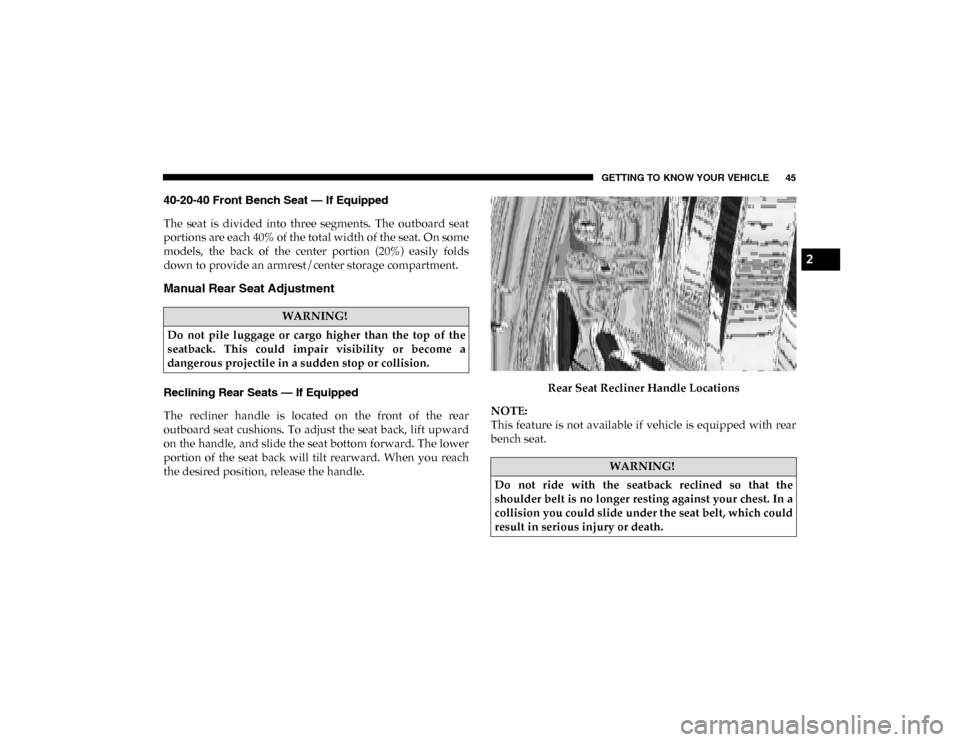
the desired position, release the handle.Rear Seat Recliner Handle Locations
NOTE:
This feature is not available if vehicle is equipped with rear
bench seat.
WARNING!
Do not pile luggage or cargo higher than the top of the
seatback. This could impair visibility or become a
dangerous projectile in a sudden stop or collision.
WARNING!
Do not ride with the seatback reclined so that the
shoulder belt is no longer resting against your chest. In a
collision you could slide under the seat belt, which could
result in serious injury or death.
2
2020_DT_1500_OM_US.book Page 45
Page 213 of 674
SAFETY 211
AUXILIARY DRIVING SYSTEMS
Blind Spot Monitoring (BSM) — If Equipped
The Blind Spot Monitoring (BSM) system uses two
radar-based sensors, located inside the taillights, to detect
highway licensable vehicles (automobiles, trucks, motorcy-
cles, etc.) that enter the blind spot zones from the rear/front/
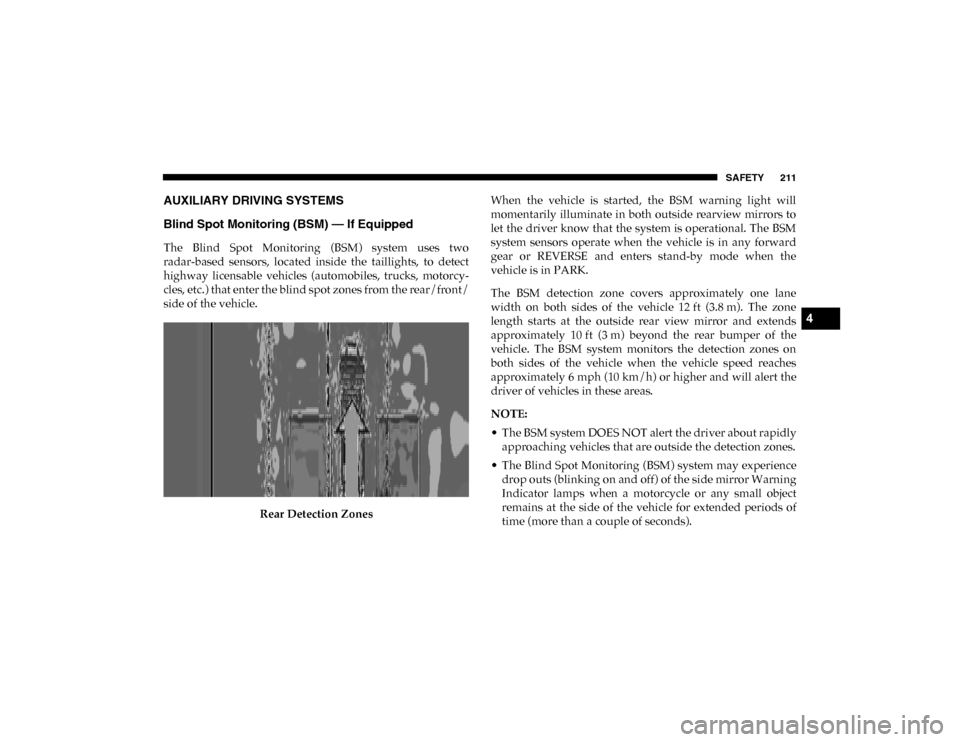
side of the vehicle.
Rear Detection Zones When the vehicle is started, the BSM warning light will
momentarily illuminate in both outside rearview mirrors to
let the driver know that the system is operational. The BSM
system sensors operate when the vehicle is in any forward
gear or REVERSE and enters stand-by mode when the
vehicle is in PARK.
The BSM detection zone covers approximately one lane
width on both sides of the vehicle 12 ft (3.8 m). The zone
length starts at the outside rear view mirror and extends
approximately 10 ft (3 m) beyond the rear bumper of the
vehicle. The BSM system monitors the detection zones on
both sides of the vehicle when the vehicle speed reaches
approximately 6 mph (10 km/h) or higher and will alert the
driver of vehicles in these areas.
NOTE:
• The BSM system DOES NOT alert the driver about rapidly
approaching vehicles that are outside the detection zones.
• The Blind Spot Monitoring (BSM) system may experience drop outs (blinking on and off) of the side mirror Warning
Indicator lamps when a motorcycle or any small object
remains at the side of the vehicle for extended periods of
time (more than a couple of seconds).
4
2020_DT_1500_OM_US.book Page 211
Page 221 of 674
SAFETY 219
The vehicle must be moving above 6 mph (10 km/h) to
activate the feature. Once the trailer has been detected, the
system will default to the maximum blind spot zone until
the length has been verified. You will see “Auto” in the
instrument panel cluster .
• Max Mode — When “Max Mode” is selected, the system
will default to the maximum blind spot zone regardless of
what size trailer is attached
NOTE:
Selected setting is stored when the ignition is cycled OFF. To
change this setting, it must be selected through the Uconnect
Settings. Refer to “Uconnect Settings” in “Multimedia” for
further information.
Trailer Length Detection
Once the trailer presence has been established. The trailer
length will be established (by making a 90 degree turn) and
then the trailer length category (example 10-20 ft (3 m to
6 m)) will be displayed. This can take up to 30 seconds after
completing the turn. NOTE:
During the same ignition cycle, if the vehicle is at a standstill
for a minimum of 90 seconds, a new “trailer detection
request” is enabled by the system once the vehicle resumes
motion.
Maximum length supported by the Trailer Merge Assist
feature is 39.5 ft (12 m). Trailer length is considered the
forward most portion of the trailer hitch to the rearward
most portion of the body, bumper, or ramp of the trailer.
Maximum width supported by the Trailer Merge Assist
feature is 8.5 ft (2.59 m). Trailer width is measured at the
widest portion of the trailer and may include wheels, tires,
finders, or rails.
NOTE:
Fifth wheel or gooseneck trailers are not supported by
Trailer Merge Assist.
4
2020_DT_1500_OM_US.book Page 219
Page 222 of 674
220 SAFETY
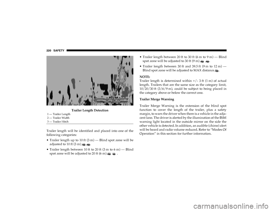
Trailer Length Detection
Trailer length will be identified and placed into one of the
following categories:
• Trailer length up to 10 ft (3 m) — Blind spot zone will be adjusted to 10 ft (3 m) .
• Trailer length between 10 ft to 20 ft (3 m to 6 m) — Blind spot zone will be adjusted to 20 ft (6 m) . • Trailer length between 20 ft to 30 ft (6 m to 9 m) — Blind
spot zone will be adjusted to 30 ft (9 m) .
• Trailer length between 30 ft and 39.5 ft (9 m to 12 m) — Blind spot zone will be adjusted to MAX distance .
NOTE:
Trailer length is determined within +/- 3 ft (1 m) of actual
length. Trailers that are the same size as the category limit,
10/20/30 ft (3/6/9 m), could be subject to being placed in
the category above or below the correct one.
Trailer Merge Warning
Trailer Merge Warning is the extension of the blind spot
function to cover the length of the trailer, plus a safety
margin, to warn the driver when there is a vehicle in the adja -
cent lane. The driver is alerted by the illumination of the BSM
warning light located in the outside mirror on the side the
other vehicle is detected. In addition, an audible (chime) alert
will be heard and radio volume reduced. Refer to “Modes Of
Operation” in this section for further information.
1 — Trailer Length
2 — Trailer Width
3 — Trailer Hitch
2020_DT_1500_OM_US.book Page 220
Page 398 of 674
396 STARTING AND OPERATING
PARKVIEW REAR BACK UP CAMERA
The ParkView Rear Back Up Camera allows you to see an
image of the rear surroundings of your vehicle whenever the
gear selector is put into REVERSE or whenever it is manually
activated. When the gear selector is put into REVERSE, the
image will be displayed in the Uconnect screen along with a
caution note to “check entire surroundings” across the top of
the screen. After five seconds this note will disappear.
Manual Activation Of The Rear View Camera:
1. Press the "Controls" button located on the bottom of theUconnect display.
2. Press the "Backup Camera" button to turn the Rear View Camera system on.
When the vehicle is shifted out of REVERSE (with Camera
delay turned off), the rear Camera mode is exited and the
previous screen appears again.
When the vehicle is shifted out of REVERSE (with Camera
delay turned on), the rear Camera image will be displayed
for up to 10 seconds after shifting to another gear, unless the
vehicle speed exceeds 8 mph (13 km/h), the transmission is shifted into PARK, the ignition is placed in the OFF position,
or the touchscreen button “X” to disable display of the Rear
View Camera image is pressed.
Whenever the Rear View Camera image is activated through
the "Backup Camera" button in the "Controls" menu, and the
vehicle speed is greater than, or equal to, 8 mph (13 km/h), a
display timer for the image is initiated. The image will
continue to be displayed until the display timer exceeds 10
seconds.
NOTE:
• If the vehicle speed remains below 8 mph (13 km/h), the Rear View Camera image will be displayed continuously
until deactivated via the touchscreen button "X", the trans -
mission is shifted into PARK, or the ignition is placed in
the OFF position.
• The touchscreen button "X" to disable display of the camera image is made available ONLY when the vehicle is
not in REVERSE.
When enabled, active guide lines are overlaid on the image
to illustrate the width of the vehicle and its projected backup
path based on the steering wheel position. The active guide
lines will show separate zones that will help indicate the
distance to the rear of the vehicle.
2020_DT_1500_OM_US.book Page 396
Page 401 of 674
STARTING AND OPERATING 399
When the vehicle is shifted into REVERSE, the rear camera
view and top view is the default view of the system (Auto-
matic Activation).
When the vehicle is shifted out of REVERSE (with camera
delay turned on), the camera image will continue to be
displayed for up to 10 seconds after shifting out of REVERSE
unless the vehicle speed exceeds 8 mph (13 km/h), the
vehicle is shifted into PARK or the ignition is placed in the
OFF position. There is a touch screen button “X” to disable
the display of the camera image.
When the vehicle is shifted out of REVERSE (with camera
delay turned off), the surround view camera mode is exited
and the last known screen appears again.
While the “rear view” is displayed, and if enabled, active
guide lines are overlaid on the image to illustrate the width
of the vehicle, including the side view mirrors and its
projected backup path based on the steering wheel position.
Different colored zones indicate the distance to the rear of
the vehicle. The following table shows the approximate distances for
each zone:
Modes Of Operation
Standard Backup Camera view can be manually activated by
selecting “Backup Camera” through the Controls menu
within the Uconnect screen.
Refer to “Parkview Rear Back Up Camera — If Equipped” in
this chapter for more information on activation conditions.
Zone
Distance To The Rear Of The
Vehicle
Red 0 - 1 ft (0 - 30 cm)
Yellow 1 ft - 6.5 ft (30 cm - 2 m)
Green 6.5 ft or greater
(2 m or greater)
5
2020_DT_1500_OM_US.book Page 399
Page 410 of 674
408 STARTING AND OPERATING
Gross Combination Weight Rating (GCWR)
The Gross Combination Weight Rating (GCWR) is the total
allowable weight of your vehicle and trailer when weighed
in combination.
Gross Axle Weight Rating (GAWR)
The Gross Axle Weight Rating (GAWR) is the maximum
capacity of the front and rear axles. Distribute the load over
the front and rear axles evenly. Make sure that you do not
exceed either front or rear GAWR. Refer to “Vehicle
Loading/Vehicle Certification Label” in “Starting And
Operating” for further information.Tongue Weight (TW)
The Tongue Weight (TW) is the downward force exerted on
the hitch ball by the trailer. You must consider this as part of
the load on your vehicle.
Trailer Frontal Area
The frontal area is the maximum height multiplied by the
maximum width of the front of a trailer.
Trailer Sway Control
The Trailer Sway Control (TSC) can be a mechanical tele
-
scoping link that can be installed between the hitch receiver
and the trailer tongue that typically provides adjustable fric -
tion associated with the telescoping motion to dampen any
unwanted trailer swaying motions while traveling.
WARNING!
If the gross trailer weight is 5,000 lbs (2,267 kg) or more,
it is recommended to use a weight-distributing hitch to
ensure stable handling of your vehicle. If you use a
standard weight-carrying hitch, you could lose control of
your vehicle and cause a collision.WARNING!
It is important that you do not exceed the maximum front
or rear GAWR. A dangerous driving condition can result
if either rating is exceeded. You could lose control of the
vehicle and have a collision.
2020_DT_1500_OM_US.book Page 408
Page 519 of 674
SERVICING AND MAINTENANCE 517
NOTE:
• P (Passenger) — Metric tire sizing is based on US designstandards. P-Metric tires have the letter “P” molded into
the sidewall preceding the size designation. Example:
P215/65R15 95H.
• European — Metric tire sizing is based on European design standards. Tires designed to this standard have the
tire size molded into the sidewall beginning with the
section width. The letter "P" is absent from this tire size
designation. Example: 215/65R15 96H.
• LT (Light Truck) — Metric tire sizing is based on US design standards. The size designation for LT-Metric tires is the same as for P-Metric tires except for the letters “LT” that
are molded into the sidewall preceding the size designa
-
tion. Example: LT235/85R16.
• Temporary spare tires are designed for temporary emer -
gency use only. Temporary high pressure compact spare
tires have the letter “T” or “S” molded into the sidewall
preceding the size designation. Example: T145/80D18
103M.
• High flotation tire sizing is based on US design standards and it begins with the tire diameter molded into the side -
wall. Example: 31x10.5 R15 LT.
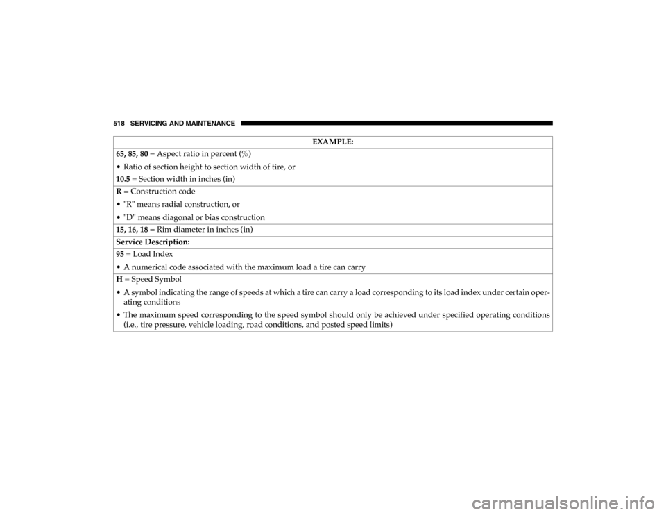
Tire Sizing Chart EXAMPLE:
Example Size Designation: P215/65R15XL 95H, 215/65R15 96H, LT235/85R16C, T145/80D18 103M, 31x10.5 R15 LT
P = Passenger car tire size based on US design standards, or
"....blank...." = Passenger car tire based on European design standards, or
LT = Light truck tire based on US design standards, or
T or S = Temporary spare tire or
31 = Overall diameter in inches (in)
215, 235, 145 = Section width in millimeters (mm)
7
2020_DT_1500_OM_US.book Page 517
Page 520 of 674
518 SERVICING AND MAINTENANCE
65, 85, 80 = Aspect ratio in percent (%)
• Ratio of section height to section width of tire, or
10.5 = Section width in inches (in)
R = Construction code
• "R" means radial construction, or
• "D" means diagonal or bias construction
15, 16, 18 = Rim diameter in inches (in)
Service Description:
95 = Load Index
• A numerical code associated with the maximum load a tire can carry
H = Speed Symbol
• A symbol indicating the range of speeds at which a tire can carry a load corresponding to its load index under certain oper -
ating conditions
• The maximum speed corresponding to the speed symbol should only be achieved under specified operating conditions (i.e., tire pressure, vehicle loading, road conditions, and posted speed limits) EXAMPLE:
2020_DT_1500_OM_US.book Page 518
Page 583 of 674
MULTIMEDIA 581
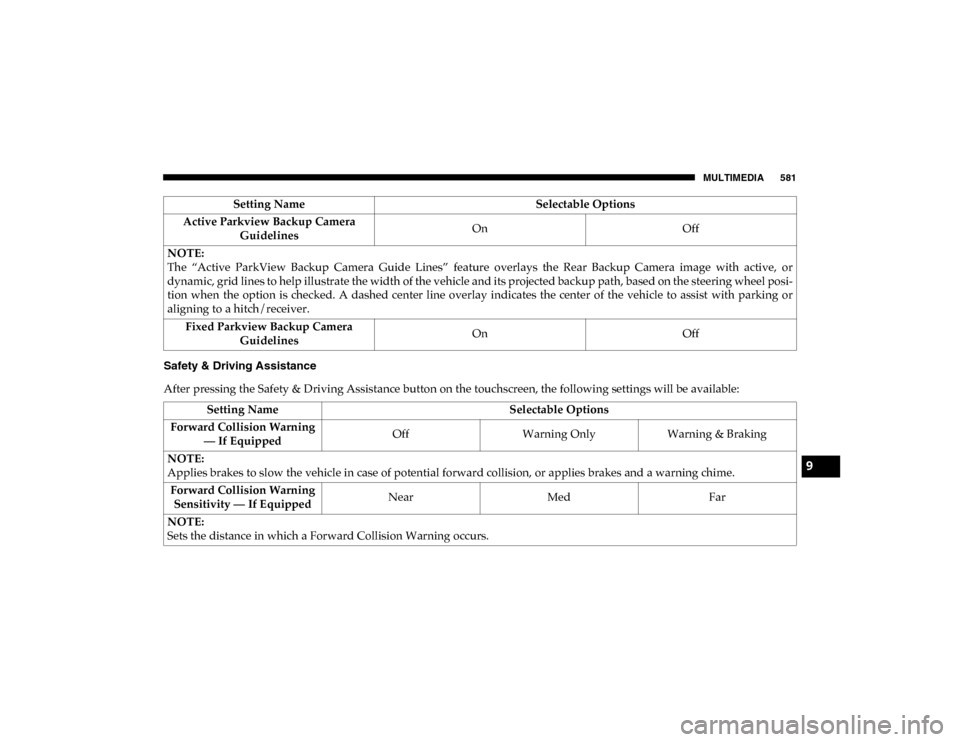
Safety & Driving Assistance
After pressing the Safety & Driving Assistance button on the touchscreen, the following settings will be available:Active Parkview Backup Camera
Guidelines On
Off
NOTE:
The “Active ParkView Backup Camera Guide Lines” feature overlays the Rear Backup Camera image with active, or
dynamic, grid lines to help illustrate the width of the vehicle and its projected backup path, based on the steering wheel posi -
tion when the option is checked. A dashed center line overlay indicates the center of the vehicle to assist with parking or
aligning to a hitch/receiver.
Fixed Parkview Backup Camera Guidelines On
Off
Setting Name
Selectable Options
Setting NameSelectable Options
Forward Collision Warning — If Equipped Off
Warning Only Warning & Braking
NOTE:
Applies brakes to slow the vehicle in case of potential forward collision, or applies brakes and a warning chime. Forward Collision Warning Sensitivity — If Equipped Near
Med Far
NOTE:
Sets the distance in which a Forward Collision Warning occurs.
9
2020_DT_1500_OM_US.book Page 581