tow RAM 1500 2022 Owners Manual
[x] Cancel search | Manufacturer: RAM, Model Year: 2022, Model line: 1500, Model: RAM 1500 2022Pages: 496, PDF Size: 18.03 MB
Page 400 of 496

398SERVICING AND MAINTENANCE
SCHEDULED SERVICING — DIESEL ENGINE
Your vehicle is equipped with an automatic oil
change indicator system. The oil change indicator
system will remind you that it is time to take your
vehicle in for scheduled maintenance.
Based on engine operation conditions, the oil
change indicator message will illuminate. This
means that service is required for your vehicle.
Operating conditions such as frequent short-trips,
trailer tow, extremely hot or cold ambient
temperatures will influence when the “Oil Change
Required” message is displayed. Have your vehicle
serviced as soon as possible, within the next
500 miles (805 km). An authorized dealer will reset the oil change
indicator message after completing the scheduled
oil change. If a scheduled oil change is performed
by someone other than an authorized dealer, the
message can be reset by referring to the steps
described under Instrument Cluster Display
Ú
page 114.
NOTE:Under no circumstances should oil change
intervals exceed 10,000 miles (16,000 km) or
12 months, whichever comes first. Once A Month Or Before A Long Trip:
Check engine oil level.
Check windshield washer fluid level.
Check the tire inflation pressures and look for
unusual wear or damage.
Check the fluid levels of the coolant reservoir,
brake master cylinder, and power steering, and
fill as needed.
Check function of all interior and exterior lights.
22_DT_OM_EN_USC_t.book Page 398
Page 402 of 496
400SERVICING AND MAINTENANCE
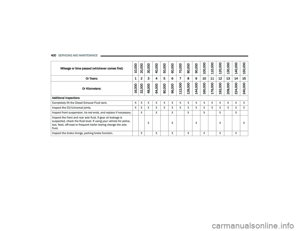
Mileage or time passed (whichever comes first)
10,000
20,000
30,000
40,000
50,000
60,000
70,000
80,000
90,000
100,000
110,000
120,000
130,000
140,000
150,000
Or Years: 1 2 3 4 5 6 7 8 9 10 11 12 13 14 15
Or Kilometers:
16,000
32,000
48,000
64,000
80,000
96,000
112,000
128,000
144,000
160,000
176,000
192,000
208,000
224,000
240,000
Additional Inspections
Completely fill the Diesel Exhaust Fluid tank. X X X X X X X X X X X X X X X
Inspect the CV/Universal joints. X X X X X X X X X X X X X X X
Inspect front suspension, tie rod ends, and replace if necessary. X X X X X X X Inspect the front and rear axle fluid. If gear oil leakage is
suspected, check the fluid level. If using your vehicle for police,
taxi, fleet, off-road or frequent trailer towing change the axle
fluid. X
XXXX
Inspect the brake linings, parking brake function. X X X X X X X
22_DT_OM_EN_USC_t.book Page 400
Page 404 of 496
402SERVICING AND MAINTENANCE
ADDITIONAL MAINTENANCE — B6 TO
B20 B
IODIESEL
NOTE:
Under no circumstances should oil change inter -
vals exceed 8,000 miles (12,875 km) or six months, whichever comes first when using
biodiesel blends greater than 5% (B5).
The owner is required to monitor mileage for
B6-B20 biodiesel, the automatic oil change indi -
cator system does not reflect the use of
biofuels.
Fuel filter change interval is maintained at every
second oil change. This is especially important
with biodiesel usage.
For more information on using biodiesel
Ú page 470.
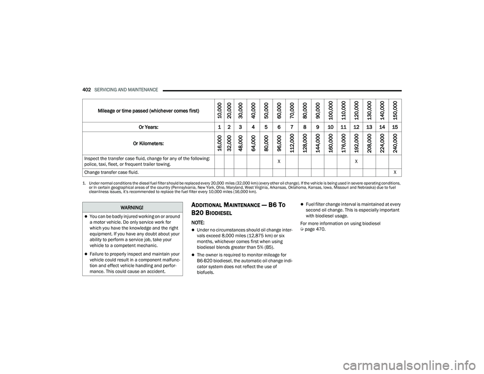
Inspect the transfer case fluid, change for any of the following:
police, taxi, fleet, or frequent trailer towing.
X
X
Change transfer case fluid. X
1. Under normal conditions the diesel fuel filter should be replaced every 20,000 miles (32,000 km) (every other oil change). If the vehicle is being used in severe operating conditions,
or In certain geographical areas of the country (Pennsylvania, New York, Ohio, Maryland, West Virginia, Arkansas, Oklahoma, Kansas, Iowa, Missouri and Nebraska) due to fuel
cleanliness issues, it’s recommended to replace the fuel filter every 10,000 miles (16,000 km).
Mileage or time passed (whichever comes first)
10,000
20,000
30,000
40,000
50,000
60,000
70,000
80,000
90,000
100,000
110,000
120,000
130,000
140,000
150,000
Or Years: 1 2 3 4 5 6 7 8 9 10 11 12 13 14 15
Or Kilometers:
16,000
32,000
48,000
64,000
80,000
96,000
112,000
128,000
144,000
160,000
176,000
192,000
208,000
224,000
240,000
WARNING!
You can be badly injured working on or around
a motor vehicle. Do only service work for
which you have the knowledge and the right
equipment. If you have any doubt about your
ability to perform a service job, take your
vehicle to a competent mechanic.
Failure to properly inspect and maintain your
vehicle could result in a component malfunc -
tion and effect vehicle handling and perfor -
mance. This could cause an accident.
22_DT_OM_EN_USC_t.book Page 402
Page 409 of 496
SERVICING AND MAINTENANCE407
CHECKING OIL LEVEL
To ensure proper engine lubrication, the engine oil
must be maintained at the correct level. Check the
oil level at regular intervals, such as every fuel
stop. The best time to check the engine oil level is
about five minutes after a fully warmed up engine
is shut off.
Checking the oil while the vehicle is on level ground
will improve the accuracy of the oil level readings.
There are four possible dipstick types:
Crosshatched zone.
Crosshatched zone marked SAFE.
Crosshatched zone marked with MIN at the low
end of the range and MAX at the high end of the
range.
Crosshatched zone marked with dimples at the
MIN and the MAX ends of the range.
NOTE:Always maintain the oil level within the crosshatch
markings on the dipstick.
Adding 1 quart (1.0 liter) of oil when the reading is
at the low end of the dipstick range will raise the oil
level to the high end of the range marking.
ADDING WASHER FLUID
The fluid reservoir is located under the hood and
should be checked for fluid level at regular
intervals. Fill the reservoir with windshield washer
solvent only (not radiator antifreeze). When
refilling the washer fluid reservoir, take some
washer fluid and apply it to a cloth or towel and
wipe the wiper blades clean. This will help blade
performance.
To prevent freeze-up of your windshield washer
system in cold weather, select a solution or mixture
that meets or exceeds the temperature range of
your climate. This rating information can be found
on most washer fluid containers. After the engine has warmed up, operate the
defroster for a few minutes to reduce the
possibility of smearing or freezing the fluid on the
cold windshield. Windshield washer solution used
with water as directed on the container, aids
cleaning action, reduces the freezing point to avoid
line clogging, and is not harmful to paint or trim.
CAUTION!
Overfilling or underfilling the crankcase will
cause oil aeration or loss of oil pressure. This
could damage your engine.
WARNING!
Commercially available windshield washer
solvents are flammable. They could ignite and
burn you. Care must be exercised when filling or
working around the washer solution.
8
22_DT_OM_EN_USC_t.book Page 407
Page 418 of 496

416SERVICING AND MAINTENANCE
Cabin Air Filter Replacement
For the proper maintenance intervals Úpage 394.
The cabin air filter is located in the fresh air inlet
behind the glove compartment. Perform the
following procedure to replace the filter:
1. Open the glove compartment and remove all contents.
2. With the glove compartment door open, remove the glove compartment tension tether
and tether clip by sliding the clip toward the
face of the glove compartment door. Lift the
clip out of glove compartment door and
release into dash panel.
Right Side Of Glove Compartment
3. There are glove compartment travel stops on both sides of the glove compartment door.
Push inward on both sides of the glove
compartment to release the glove
compartment travel stops.
Glove Compartment
4. Disengage the glove compartment door from its hinges by opening the glove compartment
past the travel stop and pulling it toward you.
5. Remove the filter cover by pushing in on the finger tabs on each end of the filter cover.
WARNING!
Do not remove the cabin air filter while the
vehicle is running, or while the ignition is in the
ACC or ON/RUN mode. With the cabin air filter
removed and the blower operating, the blower
can contact hands and may propel dirt and
debris into your eyes, resulting in personal injury.
1 — Glove Compartment Door
2 — Glove Compartment Tension Tether1 — Glove Compartment Travel Stop
2 — Glove Compartment Tension Tether
3 — Glove Compartment Door
22_DT_OM_EN_USC_t.book Page 416
Page 419 of 496

SERVICING AND MAINTENANCE417
Filter Cover
Filter Cover Removal
6. Remove the cabin air filter by pulling it straight
out of the housing.
Cabin Air Filter
7. Install the cabin air filter with the arrow on the filter pointing toward the floor. When installing
the filter cover, press on each end until you
hear an audible click.
8. Reinstall the glove compartment on the hinges. 9. Pull the tension tether outward and reinstall
the glove compartment past the travel stops by
pushing in on the glove compartment sides.
Glove Compartment
NOTE:Ensure the glove compartment door hinges and
glove compartment travel stops are fully engaged.
10. Reattach the glove compartment tension tether by inserting the tether clip in the glove
compartment and sliding the clip away from
the face of the glove compartment door.
1 — Finger Tabs
CAUTION!
The cabin air filter is identified with an arrow to
indicate airflow direction through the filter.
Failure to properly install the filter will result in
the need to replace it more often.
1 — Glove Compartment Travel Stop
2 — Glove Compartment Tension Tether
3 — Glove Compartment Door
8
22_DT_OM_EN_USC_t.book Page 417
Page 422 of 496
420SERVICING AND MAINTENANCE
(Continued)
2. To disengage the wiper blade from the wiper
arm, press the release tab on the wiper blade
and while holding the wiper arm with one
hand, slide the wiper blade down towards the
base of the wiper arm.
Wiper Blade With Release Tab In Unlocked Position
3. With the wiper blade disengaged, remove the wiper blade from the wiper arm.
4. Gently lower the wiper arm onto the glass. Installing The Front Wipers
1. Lift the wiper arm off of the glass, until the
wiper arm is in the full up position.
2. Position the wiper blade near the hook on the tip of the wiper arm.
3. Slide the wiper blade up into the hook on the wiper arm, latch engagement will be
accompanied by an audible click.
4. Gently lower the wiper blade onto the glass.
EXHAUST SYSTEM
The best protection against carbon monoxide entry
into the vehicle body is a properly maintained
engine exhaust system.
If you notice a change in the sound of the exhaust
system; or if the exhaust fumes can be detected
inside the vehicle; or when the underside or rear of
the vehicle is damaged; have an authorized
technician inspect the complete exhaust system
and adjacent body areas for broken, damaged,
deteriorated, or mispositioned parts. Open seams
or loose connections could permit exhaust fumes
to seep into the passenger compartment. In
addition, have the exhaust system inspected each
time the vehicle is raised for lubrication or oil
change. Replace as required.
1 — Wiper Blade
2 — Wiper Arm J Hook
3 — J Hook Retainer
WARNING!
Exhaust gases can injure or kill. They contain
Carbon Monoxide (CO), which is colorless and
odorless. Breathing it can make you uncon
-
scious and can eventually poison you. To
avoid breathing CO see Ú page 368.
A hot exhaust system can start a fire if you
park over materials that can burn. Such mate -
rials might be grass or leaves coming into
contact with your exhaust system. Do not park
or operate your vehicle in areas where your
exhaust system can contact anything that can
burn.
CAUTION!
The catalytic converter requires the use of
unleaded fuel only. Leaded gasoline will
destroy the effectiveness of the catalyst as an
emissions control device and may seriously
reduce engine performance and cause
serious damage to the engine.
22_DT_OM_EN_USC_t.book Page 420
Page 423 of 496
SERVICING AND MAINTENANCE421
(Continued)
Under normal operating conditions, the catalytic
converter will not require maintenance. However, it
is important to keep the engine properly tuned to
assure proper catalyst operation and prevent
possible catalyst damage.
NOTE:Intentional tampering with emissions control
systems can result in civil penalties being
assessed against you.
In unusual situations involving grossly
malfunctioning engine operation, a scorching odor
may suggest severe and abnormal catalyst
overheating. If this occurs, stop the vehicle, turn off
the engine and allow it to cool. Service, including a
tune-up to manufacturer's specifications, should
be obtained immediately. To minimize the possibility of catalytic converter
damage:
Do not interrupt the ignition when the transmis
-
sion is in gear and the vehicle is in motion.
Do not try to start the vehicle by pushing or
towing the vehicle.
Do not idle the engine with any ignition compo -
nents disconnected or removed, such as when
diagnostic testing, or for prolonged periods
during very rough idle or malfunctioning oper -
ating conditions.
COOLING SYSTEM
Engine Coolant Checks
Check the engine coolant (antifreeze) protection
every 12 months (before the onset of freezing
weather, where applicable). If the engine coolant is
dirty or rusty in appearance, the system should be
drained, flushed and refilled with fresh coolant.
Check the front of the A/C condenser (if equipped)
or radiator for any accumulation of bugs, leaves,
etc. If dirty, clean by gently spraying water from a
garden hose vertically down the face of the A/C
condenser (if equipped) or the back of the radiator
core.
Check the engine cooling system hoses for brittle
rubber, cracking, tears, cuts and tightness of the
connection at the coolant recovery bottle and
radiator. Inspect the entire system for leaks.
DO NOT REMOVE THE COOLANT PRESSURE CAP
WHEN THE COOLING SYSTEM IS HOT.
Damage to the catalytic converter can result if
your vehicle is not kept in proper operating
condition. In the event of engine malfunction,
particularly involving engine misfire or other
apparent loss of performance, have your
vehicle serviced promptly. Continued opera -
tion of your vehicle with a severe malfunction
could cause the converter to overheat,
resulting in possible damage to the converter
and vehicle.
CAUTION!
WARNING!
You or others can be badly burned by hot
engine coolant (antifreeze) or steam from your
radiator. If you see or hear steam coming from
under the hood, do not open the hood until the
radiator has had time to cool. Never open a
cooling system pressure cap when the radi -
ator or coolant bottle is hot.
Keep hands, tools, clothing, and jewelry away
from the radiator cooling fan when the hood is
raised. The fan starts automatically and may
start at any time, whether the engine is
running or not.
When working near the radiator cooling fan,
disconnect the fan motor lead or turn the igni -
tion to the OFF mode. The fan is temperature
controlled and can start at any time the igni -
tion is in the ON mode.
WARNING!
8
22_DT_OM_EN_USC_t.book Page 421
Page 432 of 496

430SERVICING AND MAINTENANCE
F05 ––Spare
F06 –10 Amp Red OUTPUT TO UPFITTER PDC *
F07 ––Spare
F08 20 Amp Blue –Trailer Tow Backup
F09 –20 Amp Yellow Trailer Stop / Turn Lamp Left
F10 –20 Amp Yellow Trailer Stop / Turn Lamp Right
F11 –15 Amp Blue ID/CLEARANCE LIGHTS *
F12 20 Amp Blue –Trailer Tow Park Lamp
F13 ––Spare
F14 –10 Amp Red AC Clutch
F15 –5 Amp Tan Intelligent Battery Sensor (IBS)
F16 ––Spare *
F17 –20 Amp Yellow Air Suspension
F18 –15 Amp Blue AGS / Rear Axle Cooling Valve / Active Air Dam
F19 ––Spare
F20 –20 Amp Yellow Adjustable Pedals *
F21 30 Amp Pink –Power Side Step *
F22 50 Amp Red –Air Module *
F23 ––Spare
F24 –20 Amp Yellow TCM SBW
Cavity Cartridge Fuse Micro Fuse Description
* If Equipped
22_DT_OM_EN_USC_t.book Page 430
Page 436 of 496

434SERVICING AND MAINTENANCE
Internal Fuse Chart
Cavity Cartridge Fuse Micro Fuse Description
* If Equipped
F01 30 Amp Pink –Trailer Tow Receptacle
F02 ––Spare
F03 –20 Amp Yellow Module Seat Heater Front (Pass)
F04 ––Spare
F05 –20 Amp Yellow Module PPU Cooling Fan *
F06 ––Spare
F07 40 Amp Green –Mod CBC 3 PWR Locks
F08 ––Spare
F09 ––Spare
F10 40 Amp Green –HVAC Blower Motor
F11 –5 Amp TanOutput to Under-hood Power Distribution Center (UPDC) Run
Coil
F12 –25 Amp Clear Mod Audio Amplifier / Active Noise Cancellation
F13 –20 Amp Yellow Mod Seat Heater Front (Driver)
F14 –15 Amp Blue Mod Seat Heater Front (Steering Wheel)
F15 ––Spare
F16 ––Spare
F17 –20 Amp Yellow LT Spot Lamp *
F18 30 Amp Pink –Motor Sunshade Sunroof
22_DT_OM_EN_USC_t.book Page 434