ECO mode RAM 1500 2022 Service Manual
[x] Cancel search | Manufacturer: RAM, Model Year: 2022, Model line: 1500, Model: RAM 1500 2022Pages: 496, PDF Size: 18.03 MB
Page 180 of 496
178STARTING AND OPERATING
(Continued)
Pushing the on/off button or placing the ignition in
the OFF position, erases the set speed from
memory.
ADAPTIVE CRUISE CONTROL (ACC)
Adaptive Cruise Control (ACC) increases the driving
convenience provided by Cruise Control while
traveling on highways and major roadways.
However, it is not a safety system and not designed
to prevent collisions. The Cruise Control function
performs differently
Ú page 176.
ACC will allow you to keep Cruise Control engaged
in light to moderate traffic conditions without the
constant need to reset your speed. ACC utilizes a
radar sensor and a forward facing camera
designed to detect a vehicle directly ahead of you
to maintain a set speed.
NOTE:
If the ACC sensor detects a vehicle ahead, ACC
will apply limited braking or acceleration (not to
exceed the original set speed) automatically to
maintain a preset following distance, while
matching the speed of the vehicle ahead.
Any chassis/suspension or tire size modifica -
tions to the vehicle will affect the performance
of the Adaptive Cruise Control and Forward Colli -
sion Warning system.
Fixed Speed Cruise Control (ACC not enabled)
will not detect vehicles directly ahead of you.
Always be aware of the feature selected
Ú page 480.
WARNING!
Adaptive Cruise Control (ACC) is a conve -
nience system. It is not a substitute for active
driver involvement. It is always the driver’s
responsibility to be attentive of road, traffic,
and weather conditions, vehicle speed,
distance to the vehicle ahead; and, most
importantly, brake operation to ensure safe
operation of the vehicle under all road condi -
tions. Your complete attention is always
required while driving to maintain safe control
of your vehicle. Failure to follow these warn -
ings can result in a collision and death or
serious personal injury.
The ACC system:
Does not react to pedestrians, oncoming
vehicles, and stationary objects (e.g., a
stopped vehicle in a traffic jam or a
disabled vehicle).
Cannot take street, traffic, and weather
conditions into account, and may be
limited upon adverse sight distance condi -
tions.
Does not always fully recognize complex
driving conditions, which can result in
wrong or missing distance warnings.
Will bring your vehicle to a complete stop
while following a vehicle ahead and hold
your vehicle for approximately three
minutes in the stop position. If the vehicle
ahead does not start moving within three
minutes the parking brake will be acti -
vated, and the ACC system will be
cancelled.
You should switch off the ACC system:
When driving in fog, heavy rain, heavy snow,
sleet, heavy traffic, and complex driving situa -
tions (i.e., in highway construction zones).
When entering a turn lane or highway off
ramp; when driving on roads that are winding,
icy, snow-covered, slippery, or have steep
uphill or downhill slopes.
When towing a trailer up or down steep slopes.
When circumstances do not allow safe driving
at a constant speed.
WARNING!
22_DT_OM_EN_USC_t.book Page 178
Page 181 of 496

STARTING AND OPERATING179
Adaptive Cruise Control (ACC) Operation
The buttons on the right side of the steering wheel
operate the Adaptive Cruise Control system.
Adaptive Cruise Control Buttons
Adaptive Cruise Control (ACC) Menu
The instrument cluster display will show the
current ACC system settings. The information it
displays depends on ACC system status.
Push the Adaptive Cruise Control (ACC) on/off
button until one of the following appears in the
instrument cluster display: Adaptive Cruise Control Off
When ACC is deactivated, the display will read
“Adaptive Cruise Control Off.”
Adaptive Cruise Control Ready
When ACC is activated, but the vehicle speed
setting has not been selected, the display will read
“Adaptive Cruise Control Ready.”
Adaptive Cruise Control Set
When the SET (+) or the SET (-) button is pushed,
the display will read “ACC SET.”
When ACC is set, the set speed will show in the
instrument cluster display.
The ACC screen may display once again if any of
the following ACC activity occurs:
System Cancel
Driver Override
System Off
ACC Proximity Warning
ACC Unavailable Warning
The instrument cluster display will return to the last
display selected after five seconds of no ACC
display activity.
Activating Adaptive Cruise Control (ACC)
The minimum set speed for the ACC system is
20 mph (32 km/h).
When the system is turned on and in the ready
state, the instrument cluster display will read
“ACC Ready.”
When the system is off, the instrument cluster
display will read “Adaptive Cruise Control (ACC)
Off.”
NOTE:You cannot engage ACC under the following condi -
tions:
When in 4WD Low
When the brakes are applied
When the parking brake is applied
When the automatic transmission is in PARK,
REVERSE or NEUTRAL
When the vehicle speed is below the minimum
speed range
When the brakes are overheated
When the driver’s door is open at low speeds
When the driver’s seat belt is unbuckled at low
speeds
When there is a stationary vehicle in front of
your vehicle in close proximity
When Electronic Stability Control (ESC) Full Off
mode is active
1 — Distance Setting Increase
2 — Adaptive Cruise Control (ACC) On/Off
3 — Distance Setting Decrease
4
22_DT_OM_EN_USC_t.book Page 179
Page 183 of 496

STARTING AND OPERATING181
The driver switches ESC to Full Off mode
The braking temperature exceeds normal range
(overheated)
The following conditions will only cancel the ACC
system:
Driver seat belt is unbuckled at low speeds
Driver door is opened at low speeds
To Turn Off
The system will turn off and clear the set speed in
memory if:
The Adaptive Cruise Control (ACC) on/off button
is pushed
The Fixed Speed Cruise Control on/off button is
pushed
The ignition is placed in the OFF position
4WD Low is engaged
To Resume
If there is a set speed in memory, push the RES
(resume) button and then remove your foot from
the accelerator pedal. The instrument cluster
display will show the last set speed.
Resume can be used at any speed above 20 mph
(32 km/h) when only Fixed Speed Cruise Control is
being used. Resume can be used at any speed above 0 mph
(0 km/h) when ACC is active.
NOTE:
If your vehicle is at a standstill for longer than
two seconds, then the driver will either have to
push the RES (resume) button, or apply the
accelerator pedal to reengage the Adaptive
Cruise Control (ACC) to the existing set speed.
ACC cannot be resumed if there is a stationary
vehicle in front of your vehicle in close proximity.
To Vary The Speed Setting
To Increase Or Decrease The Set Speed
After setting a speed, you can increase the set
speed by pushing the SET
(+) button, or decrease
speed by pushing the SET (-) button. U.S. Speed (mph)
Pushing the SET (+)
, or SET (-) button once will
result in a 1 mph speed adjustment. Each
subsequent tap of the button results in an
adjustment of 1 mph.
If the button is continually pushed, the set
speed will continue to adjust in 5 mph incre -
ments until the button is released. The new set
speed is reflected in the instrument cluster
display.
Metric Speed (km/h)
Pushing the SET (+) , or SET (-) button once will
result in a 1 km/h speed adjustment. Each
subsequent tap of the button results in an
adjustment of 1 km/h.
If the button is continually pushed, the set
speed will continue to adjust in 10 km/h incre -
ments until the button is released. The new set
speed is reflected in the instrument cluster
display.
NOTE:When you override and push the SET (+) button or
SET (-) buttons, the new set speed will be the
current speed of the vehicle.
WARNING!
The Resume function should only be used if
traffic and road conditions permit. Resuming a
set speed that is too high or too low for
prevailing traffic and road conditions could
cause the vehicle to accelerate or decelerate too
sharply for safe operation. Failure to follow these
warnings can result in a collision and death or
serious personal injury.
4
22_DT_OM_EN_USC_t.book Page 181
Page 184 of 496
182STARTING AND OPERATING
When ACC Is Active
When you use the SET (-) button to decelerate, if
the engine’s braking power does not slow the
vehicle sufficiently to reach the set speed, the
brake system will automatically slow the
vehicle.
The ACC system decelerates the vehicle to a full
stop when following the vehicle in front. If your
vehicle follows the vehicle in front to a standstill,
after two seconds the driver will either have to
push the RES (resume) button, or apply the
accelerator pedal to reengage the ACC to the
existing set speed.
The ACC system maintains set speed when
driving uphill and downhill. However, a slight
speed change on moderate hills is normal. In
addition, downshifting may occur while climbing
uphill or descending downhill. This is normal
operation and necessary to maintain set speed.
When driving uphill and downhill, the ACC
system will cancel if the braking temperature
exceeds normal range (overheated).
Setting The Following Distance In ACC
The specified following distance for Adaptive
Cruise Control (ACC) can be set by varying the
distance setting between four bars (longest), three
bars (long), two bars (medium) and one bar (short).
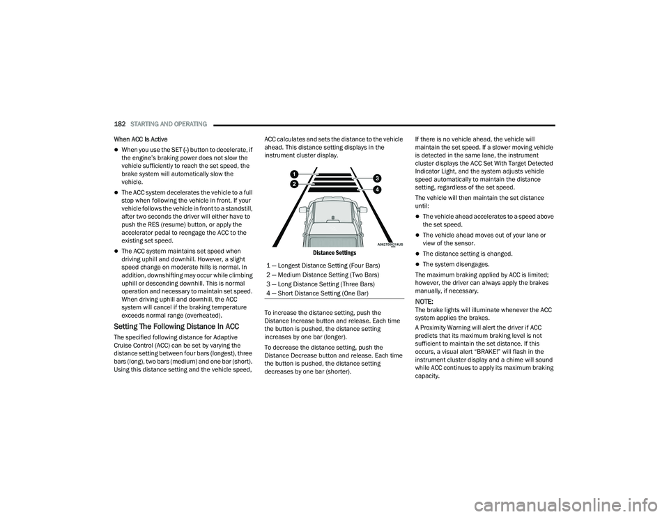
Using this distance setting and the vehicle speed, ACC calculates and sets the distance to the vehicle
ahead. This distance setting displays in the
instrument cluster display.
Distance Settings
To increase the distance setting, push the
Distance Increase button and release. Each time
the button is pushed, the distance setting
increases by one bar (longer).
To decrease the distance setting, push the
Distance Decrease button and release. Each time
the button is pushed, the distance setting
decreases by one bar (shorter). If there is no vehicle ahead, the vehicle will
maintain the set speed. If a slower moving vehicle
is detected in the same lane, the instrument
cluster displays the ACC Set With Target Detected
Indicator Light, and the system adjusts vehicle
speed automatically to maintain the distance
setting, regardless of the set speed.
The vehicle will then maintain the set distance
until:
The vehicle ahead accelerates to a speed above
the set speed.
The vehicle ahead moves out of your lane or
view of the sensor.
The distance setting is changed.
The system disengages.
The maximum braking applied by ACC is limited;
however, the driver can always apply the brakes
manually, if necessary.
NOTE:The brake lights will illuminate whenever the ACC
system applies the brakes.
A Proximity Warning will alert the driver if ACC
predicts that its maximum braking level is not
sufficient to maintain the set distance. If this
occurs, a visual alert “BRAKE!” will flash in the
instrument cluster display and a chime will sound
while ACC continues to apply its maximum braking
capacity.
1 — Longest Distance Setting (Four Bars)
2 — Medium Distance Setting (Two Bars)
3 — Long Distance Setting (Three Bars)
4 — Short Distance Setting (One Bar)
22_DT_OM_EN_USC_t.book Page 182
Page 201 of 496
STARTING AND OPERATING199
PARKVIEW REAR BACK UP CAMERA
The ParkView Rear Back Up Camera allows you to
see an on-screen image of the rear surroundings of
your vehicle whenever the gear selector is put into
REVERSE. The image will be displayed on the
Navigation/Multimedia radio display screen along
with a caution note to “Check Entire Surroundings”
across the top of the screen. After five seconds this
note will disappear. The ParkView Camera is
located in the center of the tailgate handle.
NOTE:Removing the tailgate will disable the rearview
camera function.
Manual Activation Of The Rear View
Camera:
1. Press the Controls button located on the bottom of the Uconnect display.
2. Press the Back Up Camera icon to turn the Rear View Camera system on.
NOTE:The ParkView Rear Back Up Camera has program -
mable modes of operation that may be selected
through the Uconnect system Ú page 234.When the vehicle is shifted out of REVERSE with
camera delay turned off, the rear camera mode is
exited and the previous screen appears. When the
vehicle is shifted out of REVERSE with camera
delay turned on, the camera image will continue to
be displayed for up to 10 seconds after shifting out
of REVERSE unless the following conditions occur:
The vehicle speed exceeds 8 mph (13 km/h), the
vehicle is shifted into PARK, the vehicle’s ignition is
placed in the OFF position, or the user presses
image defeat X to exit out of the camera video
display.
Whenever the Rear View Camera image is
activated through the Back Up Camera button in
the Controls menu, and the vehicle speed is
greater than, or equal to, 8 mph (13 km/h), a
display timer for the image is initiated. The image
will continue to be displayed until the display timer
exceeds 10 seconds.
NOTE:
If the vehicle speed remains below 8 mph
(13 km/h), the Rear View Camera image will be
displayed continuously until deactivated via the
touchscreen button X, the transmission is
shifted into PARK, or the ignition is placed in the
OFF position.
The touchscreen button X to disable display of
the camera image is made available ONLY when
the vehicle is not in REVERSE. When enabled, active guidelines are overlaid on
the image to illustrate the width of the vehicle and
its projected back up path based on the steering
wheel position. A dashed centerline overlay
indicates the center of the vehicle to assist with
parking or aligning to a hitch/receiver. Different
colored zones indicate the distance to the rear of
the vehicle. The following table shows the
approximate distances for each zone:
Zones
Distance To The Rear
Of The Vehicle
Red 0 - 1 ft (0 - 30 cm)
Yellow 1 ft - 6.5 ft
(30 cm - 2 m)
Green 6.5 ft or greater
(2 m or greater)
WARNING!
Drivers must be careful when backing up even
when using the ParkView Rear Back Up Camera.
Always check carefully behind your vehicle, and
be sure to check for pedestrians, animals, other
vehicles, obstructions, or blind spots before
backing up. You are responsible for the safety of
your surroundings and must continue to pay
attention while backing up. Failure to do so can
result in serious injury or death.
4
22_DT_OM_EN_USC_t.book Page 199
Page 203 of 496
STARTING AND OPERATING201
If the camera delay is turned on, the camera image
will display for up to 10 seconds after shifting out
of REVERSE. The camera image will stop
displaying, close, and display the previous screen
if the vehicle speed exceeds 8 mph (13 km/h), the
vehicle is shifted into PARK, or the ignition is
placed in the OFF position. The X button on the
touchscreen disables the display of the camera
image.
If the camera delay is turned off, the camera image
will close and display the previous screen after
shifting out of REVERSE.
If active guidelines are enabled, the lines are
overlaid on the image in the Rear View and Top
View to illustrate the width of the vehicle and its
projected path based on steering wheel position.
The guidelines have different colored zones to
indicate the distance an object in the view is from
the rear of the vehicle. Refer to the chart below: Modes Of Operation
Standard Rear View can be manually activated by
selecting “Back Up Camera” through the Controls
menu within the Uconnect system.
Top View
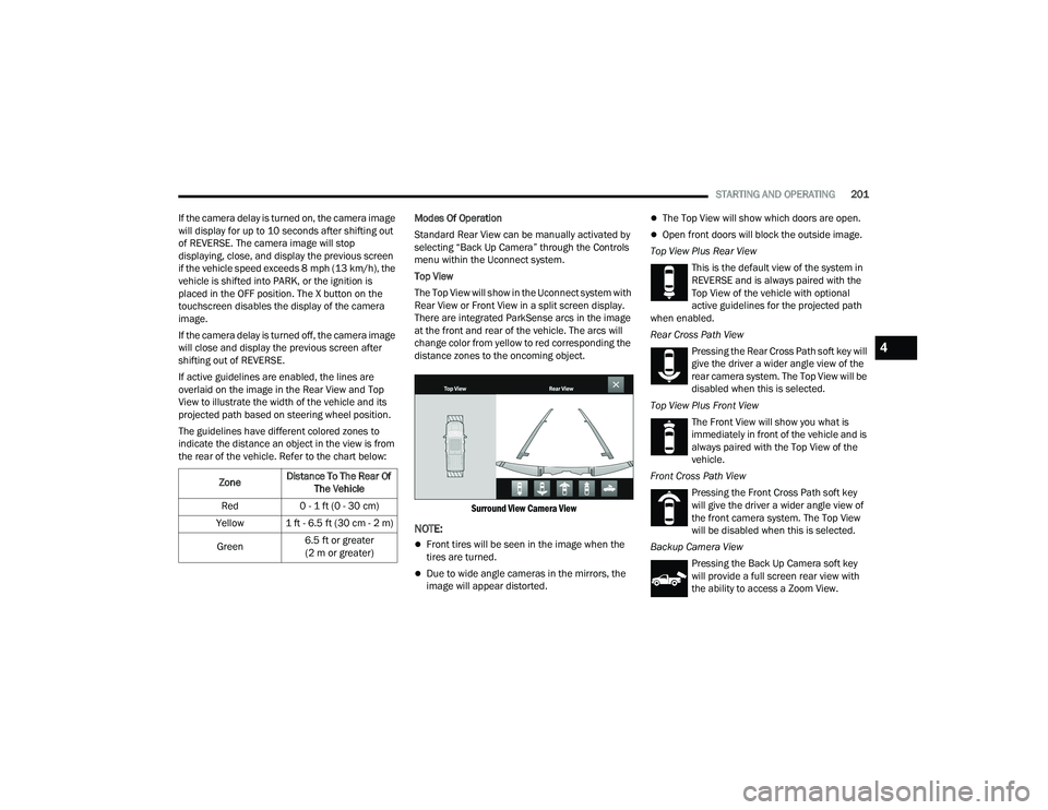
The Top View will show in the Uconnect system with
Rear View or Front View in a split screen display.
There are integrated ParkSense arcs in the image
at the front and rear of the vehicle. The arcs will
change color from yellow to red corresponding the
distance zones to the oncoming object.
Surround View Camera View
NOTE:
Front tires will be seen in the image when the
tires are turned.
Due to wide angle cameras in the mirrors, the
image will appear distorted.
The Top View will show which doors are open.
Open front doors will block the outside image.
Top View Plus Rear View This is the default view of the system in
REVERSE and is always paired with the
Top View of the vehicle with optional
active guidelines for the projected path
when enabled.
Rear Cross Path View
Pressing the Rear Cross Path soft key will
give the driver a wider angle view of the
rear camera system. The Top View will be
disabled when this is selected.
Top View Plus Front View The Front View will show you what is
immediately in front of the vehicle and is
always paired with the Top View of the
vehicle.
Front Cross Path View Pressing the Front Cross Path soft key
will give the driver a wider angle view of
the front camera system. The Top View
will be disabled when this is selected.
Backup Camera View Pressing the Back Up Camera soft key
will provide a full screen rear view with
the ability to access a Zoom View.
Zone
Distance To The Rear Of
The Vehicle
Red 0 - 1 ft (0 - 30 cm)
Yellow 1 ft - 6.5 ft (30 cm - 2 m)
Green 6.5 ft or greater
(2 m or greater)
4
22_DT_OM_EN_USC_t.book Page 201
Page 204 of 496

202STARTING AND OPERATING
NOTE:
If the Backup Camera was selected through the
Surround View Camera menu, exiting out of
screen display will return to the Surround View
menu. If the Backup Camera was manually acti -
vated through the Controls menu of the Ucon -
nect system, exiting out of the display screen
will return to the Controls menu.
When the Trailer Reverse Steering Control
(TRSC) feature (if equipped) is activated, the
following buttons on the touchscreen will be
unavailable:
Backup Camera
Front Facing Camera with Tire Lines
All Surround View Camera Views
Zoom View
When the Rear View Camera image is being
displayed, and the vehicle speed is below 8 mph
(13 km/h), Zoom View is available. By pressing the
“magnifying glass” icon in the upper left of the
display screen, the image will zoom in two times
the standard view. Pressing the icon a second time
will return the view to the standard Back Up
Camera display.
When Zoom View is selected while the vehicle is in
REVERSE, then shifted to DRIVE, the camera delay
view will display the standard Back Up Camera view. If the vehicle is then returned to REVERSE
gear from DRIVE, the Zoom View selection will
automatically resume.
Shifting to NEUTRAL from any gear will maintain
the selected view (Zoom or Standard) as long as
the vehicle is below 8 mph (13 km/h).
If the vehicle is in PARK, Zoom View is available
until the gear selector is placed in DRIVE or
REVERSE and speeds are at or above 8 mph
(13 km/h).
NOTE:
If the vehicle is in DRIVE, NEUTRAL, or REVERSE,
and speed is greater than or equal to 8 mph
(13 km/h), Zoom View is unavailable and the
icon will appear grey.
While in Zoom View, the guidelines will not be
visible.
Deactivation
The system is deactivated in the following
conditions if it was activated automatically:
When the vehicle is shifted out of REVERSE with
camera delay turned on, the camera image will
continue to be displayed for up to 10 seconds
after shifting out of REVERSE unless the vehicle
speed exceeds 8 mph (13 km/h), the vehicle is
shifted into PARK or the ignition is placed in the
OFF position. There is a touchscreen button X to
disable the display of the camera image.
When the vehicle is shifted out of REVERSE with
camera delay turned off, the Surround View
Camera mode is exited and the last known
screen appears again.
The system is deactivated in the following
conditions if it was activated manually from the
Uconnect controls menu via Surround View button
or Back Up Camera button:
The X button on the display is pressed
Vehicle is shifted into PARK
Ignition is placed in the OFF position
Vehicle speed is over 8 mph (13 km/h) for
10 seconds
NOTE:If the Surround View Camera is activated manually,
and the vehicle is shifted into REVERSE, deacti-
vation methods for automatic activation are
assumed.
The camera delay system is turned off manually
through the Uconnect settings menu Úpage 234.
NOTE:
If snow, ice, mud, or any foreign substance
builds up on the camera lenses, clean the
lenses, rinse with water, and dry with a soft
cloth. Do not cover the lenses.
If a malfunction with the system has occurred,
see an authorized dealer.
22_DT_OM_EN_USC_t.book Page 202
Page 206 of 496
204STARTING AND OPERATING
Set Up
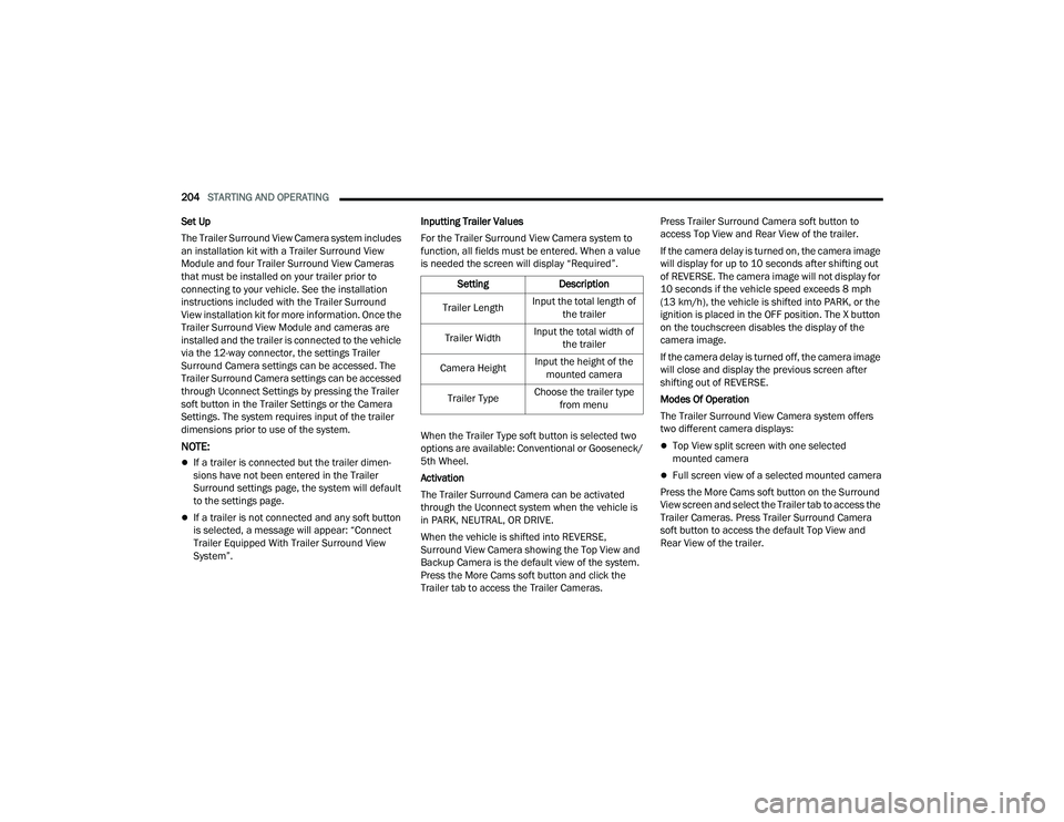
The Trailer Surround View Camera system includes
an installation kit with a Trailer Surround View
Module and four Trailer Surround View Cameras
that must be installed on your trailer prior to
connecting to your vehicle. See the installation
instructions included with the Trailer Surround
View installation kit for more information. Once the
Trailer Surround View Module and cameras are
installed and the trailer is connected to the vehicle
via the 12-way connector, the settings Trailer
Surround Camera settings can be accessed. The
Trailer Surround Camera settings can be accessed
through Uconnect Settings by pressing the Trailer
soft button in the Trailer Settings or the Camera
Settings. The system requires input of the trailer
dimensions prior to use of the system.
NOTE:
If a trailer is connected but the trailer dimen -
sions have not been entered in the Trailer
Surround settings page, the system will default
to the settings page.
If a trailer is not connected and any soft button
is selected, a message will appear: “Connect
Trailer Equipped With Trailer Surround View
System”. Inputting Trailer Values
For the Trailer Surround View Camera system to
function, all fields must be entered. When a value
is needed the screen will display “Required”.
When the Trailer Type soft button is selected two
options are available: Conventional or Gooseneck/
5th Wheel.
Activation
The Trailer Surround Camera can be activated
through the Uconnect system when the vehicle is
in PARK, NEUTRAL, OR DRIVE.
When the vehicle is shifted into REVERSE,
Surround View Camera showing the Top View and
Backup Camera is the default view of the system.
Press the More Cams soft button and click the
Trailer tab to access the Trailer Cameras. Press Trailer Surround Camera soft button to
access Top View and Rear View of the trailer.
If the camera delay is turned on, the camera image
will display for up to 10 seconds after shifting out
of REVERSE. The camera image will not display for
10 seconds if the vehicle speed exceeds 8 mph
(13 km/h), the vehicle is shifted into PARK, or the
ignition is placed in the OFF position. The X button
on the touchscreen disables the display of the
camera image.
If the camera delay is turned off, the camera image
will close and display the previous screen after
shifting out of REVERSE.
Modes Of Operation
The Trailer Surround View Camera system offers
two different camera displays:
Top View split screen with one selected
mounted camera
Full screen view of a selected mounted camera
Press the More Cams soft button on the Surround
View screen and select the Trailer tab to access the
Trailer Cameras. Press Trailer Surround Camera
soft button to access the default Top View and
Rear View of the trailer.
Setting
Description
Trailer Length Input the total length of
the trailer
Trailer Width Input the total width of
the trailer
Camera Height Input the height of the
mounted camera
Trailer Type Choose the trailer type
from menu
22_DT_OM_EN_USC_t.book Page 204
Page 207 of 496
STARTING AND OPERATING205
Top View
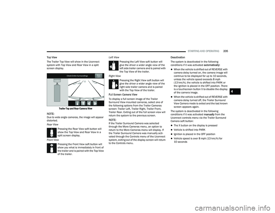
The Trailer Top View will show in the Uconnect
system with Top View and Rear View in a split
screen display.
Trailer Top and Rear Camera View
NOTE:Due to wide angle cameras, the image will appear
distorted.
Rear ViewPressing the Rear View soft button will
show the Top View and Rear View in a
split screen display.
Front View Pressing the Front View soft button will
show you what is immediately in front of
the trailer and is paired with the Top View
of the trailer. Left View
Pressing the Left View soft button will
give the driver a wider angle view of the
left side trailer camera and is paired with
the Top View of the trailer.
Right View Pressing the Right View soft button will
give the driver a wider angle view of the
right side trailer camera and is paired
with the Top View of the trailer.
Full Screen Camera View
To display a full screen image of the Trailer
Surround View mounted cameras, select one of
the following options from the Trailer Cameras
screen: Trailer Left, Trailer Right, Trailer Front,
Trailer Rear. Exiting out of the full screen view will
return the system to the previous screen.NOTE:If the Trailer Surround Camera was selected
through the More Cameras menu, an option to
return to the More Cameras menu will display. If
the Trailer Surround Camera was manually acti-
vated through the Controls menu of the Uconnect
system, exiting out of the display screen will return
to the Controls menu. Deactivation
The system is deactivated in the following
conditions if it was activated
automatically:
When the vehicle is shifted out of REVERSE with
camera delay turned on, the camera image will
continue to be displayed for up to 10 seconds,
unless the vehicle speed exceeds 8 mph
(13 km/h), the vehicle is shifted into PARK or
the ignition is placed in the OFF position. There
is a touchscreen button X to disable the display
of the camera image.
When the vehicle is shifted out of REVERSE with
camera delay turned off, the Trailer Surround
View Camera mode is exited and the last known
screen appears again.
The system is deactivated in the following
conditions if it was activated manually from the
Uconnect controls menu via the Trailer Surround
Camera soft button:
The X button on the display is pressed
Vehicle is shifted into PARK
Ignition is placed in the OFF position
Vehicle speed is over 8 mph (13 km/h) for
10 seconds
4
22_DT_OM_EN_USC_t.book Page 205
Page 217 of 496

STARTING AND OPERATING215
RECOMMENDED DISTRIBUTION HITCH
ADJUSTMENT
Towing With Air Suspension — If Equipped
1. Verify that the vehicle is at the normal ride
height.
NOTE:The vehicle must remain in the engine run position
with all doors closed while attaching a trailer for
proper leveling of the air suspension system.
2. Position the truck to be ready to connect to the trailer (do not connect the trailer).
3. Enable tire jack mode through the instrument cluster or touchscreen radio settings. Tire jack
mode will be canceled and the procedure must
be restarted if the vehicle is driven at speeds
above 5 mph (8 km/h).
4. Measure the height from the top of the front wheel opening on the fender to ground; this is
height H1.
Measuring Height (H)
5. Attach the trailer to the vehicle without the weight-distributing bars connected.
6. Measure the height from the top of the front wheel opening on the fender to the ground;
this is height H2.
7. Install and adjust the tension in the weight-distributing bars per the
manufacturer’s recommendations so that the
height of the front fender is approximately
(H2-H1)/3+H1 (about 1/3 the difference
between H2 and H1 above normal ride height
[H1]). 8. Use the instrument cluster or touchscreen
radio settings and switch off tire jack mode.
Make sure the truck returns to normal ride
height. Perform a visual inspection of the
trailer and weight-distributing hitch to confirm
the manufacturer’s recommendations have
been met.
9. The truck can now be driven.
NOTE:For all towing conditions, we recommend towing
with Tow/Haul mode engaged.
Measurement Example Example Height (mm)
H1
925
H2 946
H2-H1 21
(H2-H1)/3 7
(H2-H1)/3 + H1 932
4
22_DT_OM_EN_USC_t.book Page 215