gain RAM 1500 2022 Owners Manual
[x] Cancel search | Manufacturer: RAM, Model Year: 2022, Model line: 1500, Model: RAM 1500 2022Pages: 496, PDF Size: 18.03 MB
Page 13 of 496

11
SYMBOLS KEY
If you do not read this entire Owner’s Manual, you may miss important
information. Observe all Cautions and Warnings.
VAN CONVERSIONS/CAMPERS
The New Vehicle Limited Warranty does not apply to body modifications or
special equipment installed by van conversion/camper manufacturers/body
builders. US residents refer to the Warranty Information, Section 2.1.C.
Canadian residents refer to the “What Is Not Covered” section of the Warranty
Information. Such equipment includes video monitors, DVD/Blu-Ray™,
heaters, stoves, refrigerators, etc. For warranty coverage and service on these
items, contact the applicable manufacturer.
CONSUMER INFORMATION — TRUCK-CAMPER LOADING
This information is provided in fulfillment of the requirement by the United
States Government, Department of Transportation, National Highway Traffic
Safety Administration, that “every manufacturer of trucks that are capable of
accommodating slide-in campers, manufactured on or after April 1, 1973 shall
provide... at the time of original purchase to the first person who purchases the
truck”... information on Truck Camper Loading.
A slide-in camper document is provided in your vehicle’s glove compartment
that contains your Vehicle Identification Number, truck model, cargo weight
rating, and the forward/rearward limit of a camper. To obtain additional
dimensional and technical specifications for your vehicle, please visit
https://www.ramtrucks.com.
Figure 1 illustrates the dimensions describing the forward and rearward limits
of the zone in which the Center of Gravity (CG) of a slide-in camper must be
located, to provide satisfactory vehicle handling and to prevent overload of the
front and rear axles.
Figure 2 illustrates a proper match between truck and camper.
WARNING!
These statements are against operating
procedures that could result in a collision, bodily
injury and/or death.
CAUTION! These statements are against procedures that
could result in damage to your vehicle.
NOTE: A suggestion which will improve installation,
operation, and reliability. If not followed, may
result in damage.
TIP: General ideas/solutions/suggestions on easier
use of the product or functionality.
PAGE REFERENCE
ARROW Follow this reference for additional information on
a particular feature.
FOOTNOTE Supplementary and relevant information
pertaining to the topic.
1
22_DT_OM_EN_USC_t.book Page 11
Page 25 of 496
GETTING TO KNOW YOUR VEHICLE23
The system uses a key fob, keyless push button
ignition and a Radio Frequency (RF) receiver to
prevent unauthorized vehicle operation. Therefore,
only key fobs that are programmed to the vehicle
can be used to start and operate the vehicle. The
system cannot reprogram a key fob obtained from
another vehicle.
After placing the ignition in the ON/RUN position,
the Vehicle Security Light will turn on for three
seconds for a bulb check. If the light remains on
after the bulb check, it indicates that there is a
problem with the electronics. In addition, if the light
begins to flash after the bulb check, it indicates
that someone attempted to start the engine with
an invalid key fob. In the event that a valid key fob
is used to start the engine but there is an issue
with the vehicle electronics, the engine will start
and shut off after two seconds.
If the Vehicle Security Light turns on during normal
vehicle operation (vehicle running for longer than
10 seconds), it indicates that there is a fault in the
electronics. Should this occur, have the vehicle
serviced as soon as possible by an authorized
dealer. All of the key fobs provided with your new vehicle
have been programmed to the vehicle electronics
Ú
page 480.
IGNITION SWITCH
KEYLESS ENTER ‘N GO™ IGNITION
This feature allows the driver to operate the
ignition switch with the push of a button as long as
the key fob is in the passenger compartment.
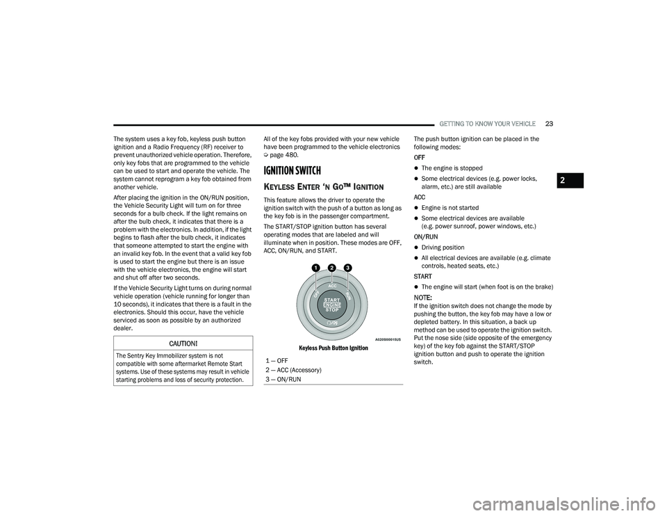
The START/STOP ignition button has several
operating modes that are labeled and will
illuminate when in position. These modes are OFF,
ACC, ON/RUN, and START.
Keyless Push Button Ignition
The push button ignition can be placed in the
following modes:
OFF
The engine is stopped
Some electrical devices (e.g. power locks,
alarm, etc.) are still available
ACC
Engine is not started
Some electrical devices are available
(e.g. power sunroof, power windows, etc.)
ON/RUN
Driving position
All electrical devices are available (e.g. climate
controls, heated seats, etc.)
START
The engine will start (when foot is on the brake)
NOTE:If the ignition switch does not change the mode by
pushing the button, the key fob may have a low or
depleted battery. In this situation, a back up
method can be used to operate the ignition switch.
Put the nose side (side opposite of the emergency
key) of the key fob against the START/STOP
ignition button and push to operate the ignition
switch.
CAUTION!
The Sentry Key Immobilizer system is not
compatible with some aftermarket Remote Start
systems. Use of these systems may result in vehicle
starting problems and loss of security protection.
1 — OFF
2 — ACC (Accessory)
3 — ON/RUN
2
22_DT_OM_EN_USC_t.book Page 23
Page 27 of 496
GETTING TO KNOW YOUR VEHICLE25
HOW TO USE REMOTE START
Push and release the Remote Start button on the
key fob twice within five seconds. The vehicle
doors will lock, the parking lights will flash, and the
horn will chirp twice (if programmed). Then, the
engine will start, and the vehicle will remain in the
Remote Start mode for a 15 minute cycle.
Pushing the Remote Start button a third time shuts
the engine off.
To drive the vehicle, push the unlock button, and
place the ignition in the ON/RUN position.
NOTE:
With Remote Start, the engine will only run for
15 minutes.
Remote Start can only be used twice.
If an engine fault is present or fuel level is low,
the vehicle will start and then shut down in
10 seconds.
The parking lights will turn on and remain on
during Remote Start mode.
For security, power window and power sunroof
operation (if equipped) are disabled when the
vehicle is in the Remote Start mode.
The ignition must be placed in the ON/RUN posi -
tion before the Remote Start sequence can be
repeated for a third cycle.
All of the following conditions must be met before
the engine will remote start:
Gear selector in PARK
Doors closed
Hood closed
Hazard switch off
Brake switch inactive (brake pedal not pressed)
Battery at an acceptable charge level
PANIC button not pushed
Fuel meets minimum requirement
System not disabled from previous Remote
Start event
Vehicle Security system not active
Malfunction Indicator Light (MIL) is not illumi -
nated
TO EXIT REMOTE START MODE
To drive the vehicle after a Remote Start, unlock
the doors using the key fob or Passive Entry and
disarm the Vehicle Security system (if equipped).
Then, prior to the end of the 15 minute cycle,
press the brake pedal and push and release the
START/STOP ignition button.
The Remote Start system will turn the engine off if
the Remote Start button on the key fob is pushed
again, or if the engine is allowed to run for the
entire 15 minute cycle. Once the ignition is placed
in the ON/RUN position, the climate controls will
resume the previously set operations
(temperature, blower control, etc.).
WARNING!
Do not start or run an engine in a closed
garage or confined area. Exhaust gas contains
Carbon Monoxide (CO) which is odorless and
colorless. Carbon Monoxide is poisonous and
can cause serious injury or death when
inhaled.
Keep key fobs away from children. Operation
of the Remote Start system, windows, door
locks or other controls could cause serious
injury or death.
WARNING!
Do not start or run an engine in a closed
garage or confined area. Exhaust gas contains
Carbon Monoxide (CO) which is odorless and
colorless. Carbon Monoxide is poisonous and
can cause serious injury or death when
inhaled.
Keep key fobs away from children. Operation
of the Remote Start system, windows, door
locks or other controls could cause serious
injury or death.
2
22_DT_OM_EN_USC_t.book Page 25
Page 36 of 496

34GETTING TO KNOW YOUR VEHICLE
HEATED STEERING WHEEL —
I
F EQUIPPED
The steering wheel contains a heating
element that helps warm your hands in
cold weather. The heated steering wheel
has only one temperature setting. Once
the heated steering wheel has been turned on, it
will stay on until the operator turns it off. The
heated steering wheel may not turn on when it is
already warm.
The heated steering wheel button is located on the
center of the instrument panel below the radio
screen, and within the Climate or Controls screen
of the touchscreen.
Press the heated steering wheel button once to
turn the heating element on.
Press the heated steering wheel button a
second time to turn the heating element off.
NOTE:The engine must be running for the heated
steering wheel to operate.
For information on use with the Remote Start
system, see Ú page 26.
DRIVER MEMORY SETTINGS — IF EQUIPPED
This feature allows the driver to save up to two
different memory profiles for easy recall through a
memory switch. Each memory profile saves
desired position settings for the following features:
Driver’s seat
Easy Entry/Exit seat operation (if equipped)
Adjustable pedals (if equipped)
Side mirrors
NOTE:Your vehicle is equipped with two key fobs, each
can be linked to either memory position 1 or 2.
The driver memory settings switch is located on the
driver door, next to the door handle, and consists
of three buttons:
The set (S) button, which is used to activate the
memory save function.
The (1) and (2) buttons which are used to recall
either of two saved memory profiles.
Memory Settings Switch
WARNING!
Persons who are unable to feel pain to the
skin because of advanced age, chronic illness,
diabetes, spinal cord injury, medication,
alcohol use, exhaustion, or other physical
conditions must exercise care when using the
steering wheel heater. It may cause burns
even at low temperatures, especially if used
for long periods.
Do not place anything on the steering wheel
that insulates against heat, such as a blanket
or steering wheel covers of any type or mate -
rial. This may cause the steering wheel heater
to overheat.
22_DT_OM_EN_USC_t.book Page 34
Page 38 of 496
36GETTING TO KNOW YOUR VEHICLE
MANUAL ADJUSTMENT (FRONT SEATS) —
I
F EQUIPPED
Manual Front Seat Forward/Rearward
Adjustment
Both front seats are adjustable forward or
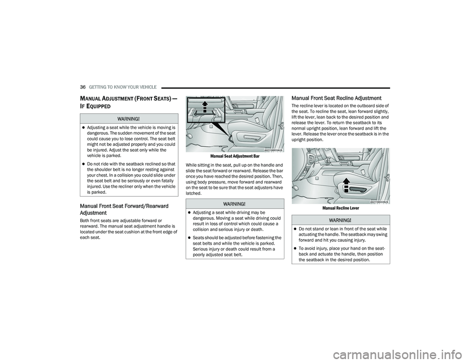
rearward. The manual seat adjustment handle is
located under the seat cushion at the front edge of
each seat.
Manual Seat Adjustment Bar
While sitting in the seat, pull up on the handle and
slide the seat forward or rearward. Release the bar
once you have reached the desired position. Then,
using body pressure, move forward and rearward
on the seat to be sure that the seat adjusters have
latched.
Manual Front Seat Recline Adjustment
The recline lever is located on the outboard side of
the seat. To recline the seat, lean forward slightly,
lift the lever, lean back to the desired position and
release the lever. To return the seatback to its
normal upright position, lean forward and lift the
lever. Release the lever once the seatback is in the
upright position.
Manual Recline Lever
WARNING!
Adjusting a seat while the vehicle is moving is
dangerous. The sudden movement of the seat
could cause you to lose control. The seat belt
might not be adjusted properly and you could
be injured. Adjust the seat only while the
vehicle is parked.
Do not ride with the seatback reclined so that
the shoulder belt is no longer resting against
your chest. In a collision you could slide under
the seat belt and be seriously or even fatally
injured. Use the recliner only when the vehicle
is parked.
WARNING!
Adjusting a seat while driving may be
dangerous. Moving a seat while driving could
result in loss of control which could cause a
collision and serious injury or death.
Seats should be adjusted before fastening the
seat belts and while the vehicle is parked.
Serious injury or death could result from a
poorly adjusted seat belt.
WARNING!
Do not stand or lean in front of the seat while
actuating the handle. The seatback may swing
forward and hit you causing injury.
To avoid injury, place your hand on the seat -
back and actuate the handle, then position
the seatback in the desired position.
22_DT_OM_EN_USC_t.book Page 36
Page 39 of 496
GETTING TO KNOW YOUR VEHICLE37
Front Bench Seat — If Equipped
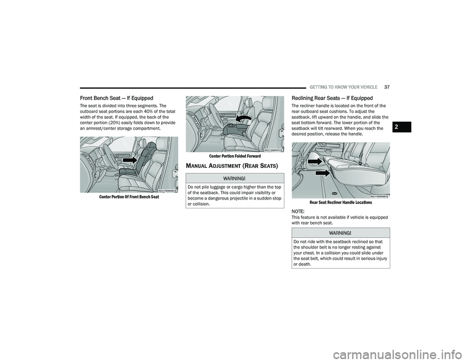
The seat is divided into three segments. The
outboard seat portions are each 40% of the total
width of the seat. If equipped, the back of the
center portion (20%) easily folds down to provide
an armrest/center storage compartment.
Center Portion Of Front Bench Seat Center Portion Folded Forward
MANUAL ADJUSTMENT (REAR SEATS)
Reclining Rear Seats — If Equipped
The recliner handle is located on the front of the
rear outboard seat cushions. To adjust the
seatback, lift upward on the handle, and slide the
seat bottom forward. The lower portion of the
seatback will tilt rearward. When you reach the
desired position, release the handle.
Rear Seat Recliner Handle Locations
NOTE:This feature is not available if vehicle is equipped
with rear bench seat.
WARNING!
Do not pile luggage or cargo higher than the top
of the seatback. This could impair visibility or
become a dangerous projectile in a sudden stop
or collision.
WARNING!
Do not ride with the seatback reclined so that
the shoulder belt is no longer resting against
your chest. In a collision you could slide under
the seat belt, which could result in serious injury
or death.
2
22_DT_OM_EN_USC_t.book Page 37
Page 40 of 496
38GETTING TO KNOW YOUR VEHICLE
POWER ADJUSTMENT (FRONT SEATS) —
I
F EQUIPPED
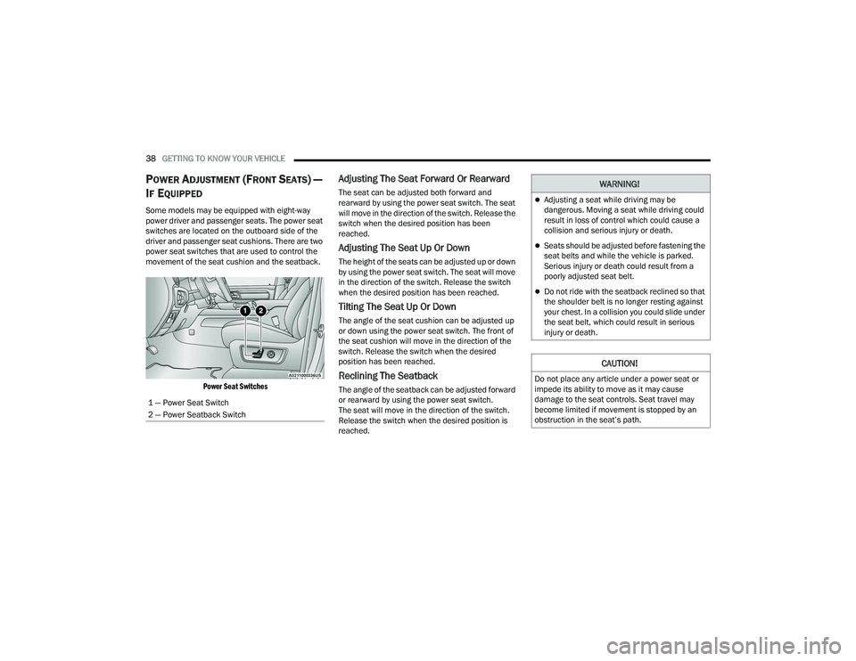
Some models may be equipped with eight-way
power driver and passenger seats. The power seat
switches are located on the outboard side of the
driver and passenger seat cushions. There are two
power seat switches that are used to control the
movement of the seat cushion and the seatback.
Power Seat Switches
Adjusting The Seat Forward Or Rearward
The seat can be adjusted both forward and
rearward by using the power seat switch. The seat
will move in the direction of the switch. Release the
switch when the desired position has been
reached.
Adjusting The Seat Up Or Down
The height of the seats can be adjusted up or down
by using the power seat switch. The seat will move
in the direction of the switch. Release the switch
when the desired position has been reached.
Tilting The Seat Up Or Down
The angle of the seat cushion can be adjusted up
or down using the power seat switch. The front of
the seat cushion will move in the direction of the
switch. Release the switch when the desired
position has been reached.
Reclining The Seatback
The angle of the seatback can be adjusted forward
or rearward by using the power seat switch.
The seat will move in the direction of the switch.
Release the switch when the desired position is
reached.
1 — Power Seat Switch
2 — Power Seatback Switch
WARNING!
Adjusting a seat while driving may be
dangerous. Moving a seat while driving could
result in loss of control which could cause a
collision and serious injury or death.
Seats should be adjusted before fastening the
seat belts and while the vehicle is parked.
Serious injury or death could result from a
poorly adjusted seat belt.
Do not ride with the seatback reclined so that
the shoulder belt is no longer resting against
your chest. In a collision you could slide under
the seat belt, which could result in serious
injury or death.
CAUTION!
Do not place any article under a power seat or
impede its ability to move as it may cause
damage to the seat controls. Seat travel may
become limited if movement is stopped by an
obstruction in the seat’s path.
22_DT_OM_EN_USC_t.book Page 38
Page 41 of 496

GETTING TO KNOW YOUR VEHICLE39
Power Lumbar — If Equipped
Vehicles equipped with power driver or passenger
seats may also be equipped with a 2-way or a
4-way power lumbar adjustment. The power
lumbar switch is located on the outboard side of
the power seat. Push the switch forward to
increase the lumbar support. Push the switch
rearward to decrease the lumbar support. If
equipped with a 4-way adjustment, pushing
upward or downward on the switch will raise and
lower the position of the support.
Power Lumbar Switch
Easy Entry/Exit Seat — If Equipped
This feature provides automatic driver’s seat
positioning to enhance driver mobility when
entering and exiting the vehicle.
The distance the driver’s seat moves depends on
where you have the driver’s seat positioned when
you place the vehicle’s ignition in the OFF position.
When you place the vehicle’s ignition in the
OFF position, the driver’s seat will move about
2.4 inches (6 cm) rearward if the driver’s seat
position is greater than or equal to 2.7 inches
(6.77 cm) forward of the rear stop. The seat will
return to its previously set position when you
place the ignition into the ACC or ON/RUN posi -
tion.
When you remove the key fob from the ignition,
the driver’s seat will move to a position
0.3 inches (0.77 cm) forward of the rear stop if
the driver’s seat position is between 0.9 inches
and 2.7 inches (2.27 cm and 6.77 cm) forward
of the rear stop. The seat will return to its previ -
ously set position when you place the ignition to
the ACC or ON/RUN position.
The Easy Entry/Easy Exit feature is disabled
when the driver’s seat position is less than
0.9 inches (2.27 cm) forward of the rear stop. At
this position, there is no benefit to the driver by
moving the seat for Easy Exit or Easy Entry. When enabled in Uconnect Settings, Easy Entry
and Easy Exit positions are stored in each memory
setting profile Ú
page 34.
NOTE:The Easy Entry/Exit feature is enabled or disabled
through the programmable features in the
Uconnect system Ú page 234.
HEATED SEATS — IF EQUIPPED
WARNING!
Persons who are unable to feel pain to the
skin because of advanced age, chronic illness,
diabetes, spinal cord injury, medication,
alcohol use, exhaustion or other physical
condition must exercise care when using the
seat heater. It may cause burns even at low
temperatures, especially if used for long
periods of time.
Do not place anything on the seat or seatback
that insulates against heat, such as a blanket
or cushion. This may cause the seat heater to
overheat. Sitting in a seat that has been over -
heated could cause serious burns due to the
increased surface temperature of the seat.
2
22_DT_OM_EN_USC_t.book Page 39
Page 43 of 496

GETTING TO KNOW YOUR VEHICLE41
Rear Ventilated Seats — If Equipped
If equipped, the two outboard rear seats
will have ventilated seats. The rear
ventilated seat control switches are
located on the rear of the center console.
The fans operate at three speeds: HI, MED, and LO.
Push the ventilated seat buttons to toggle through
the speeds, or to turn the feature off.
NOTE:The engine must be running for the ventilated
seats to operate.
PLASTIC GROCERY BAG RETAINERS
Retainer hooks which will hold plastic grocery bag
handles are attached to the underside of the rear
seat cushion. To access these hooks, lift the rear
seat cushion upward.
HEAD RESTRAINTS
Head restraints are designed to reduce the risk of
injury by restricting head movement in the event of
a rear impact. Head restraints should be adjusted
so that the top of the head restraint is located
above the top of your ear.
NOTE:Do not reverse the head restraints (making the
rear of the head restraint face forward) in an
attempt to gain additional clearance to the back of
your head.
Front Head Restraints
Your vehicle is equipped with front four-way driver
and passenger head restraints.
To raise the head restraint, pull upward on the
head restraint. To lower the head restraint, push
the adjustment button, located at the base of the
head restraint, and push downward on the head
restraint.
NOTE:The head restraints should only be removed by
qualified technicians, for service purposes only. If
either of the head restraints require removal, see
an authorized dealer.
Head Restraint Adjustment Button Location
WARNING!
All occupants, including the driver, should not
operate a vehicle or sit in a vehicle’s seat until
the head restraints are placed in their proper
positions in order to minimize the risk of neck
injury in the event of a crash.
Head restraints should never be adjusted
while the vehicle is in motion. Driving a vehicle
with the head restraints improperly adjusted
or removed could cause serious injury or
death in the event of a collision.
2
22_DT_OM_EN_USC_t.book Page 41
Page 45 of 496

GETTING TO KNOW YOUR VEHICLE43
UCONNECT VOICE RECOGNITION —
IF EQUIPPED
INTRODUCING VOICE RECOGNITION
Start using Uconnect Voice Recognition with these
helpful quick tips. It provides the key Voice
Commands and tips you need to know to control
your vehicle’s Voice Recognition (VR) system. This
system is only available on the Uconnect 3 With
5-inch Display, Uconnect 5 NAV With 8.4-inch
Display, and the Uconnect 5 NAV With 12-inch
Display.
Uconnect 3 With 5-inch Display
If you see the NAV icon on the bottom bar or in the
Apps menu of your 8.4-inch touchscreen, you have
the Uconnect 5 NAV system. If not, you have a
Uconnect 5 with 8.4-inch display system.BASIC VOICE COMMANDS
The basic Voice Commands below can be given at
any point while using your Uconnect system.
Push the VR button or for the Uconnect 5/
5 NAV, say the vehicle’s Wake Up word, “Hey
Uconnect”. After the beep, say:
“
Cancel ” to stop a current voice session.
“Help ” to hear a list of suggested Voice
Commands.
“ Repeat ” to listen to the system prompts again.
Notice the visual cues that inform you of your Voice
Recognition system’s status.
NOTE:On Uconnect 5 systems, the factory default Wake
Up word is set to “Hey Uconnect” and can be repro -
grammed through the Uconnect Settings.
GET STARTED
The VR button is used to activate/deactivate
your Voice Recognition system.
Helpful hints for using Voice Recognition:
1. Visit
UconnectPhone.com
to check mobile
device and feature compatibility and to find
phone pairing instructions.
2. Reduce background noise. Wind noise and passenger conversations are examples of
noise that may impact recognition.
3. Speak clearly at a normal pace and volume while facing straight ahead. The microphone is
located in the headliner and aimed at the
driver.
4. Each time you give a Voice Command, you must first push either the VR or Phone button,
wait until after the beep, then say your Voice
Command. You can also say the vehicle “Wake
Up” word and state your command. Some
examples of “Wake Up” words include “Hey
Uconnect” or “Hey Ram”.2
22_DT_OM_EN_USC_t.book Page 43