center console RAM 1500 2023 Owners Manual
[x] Cancel search | Manufacturer: RAM, Model Year: 2023, Model line: 1500, Model: RAM 1500 2023Pages: 416, PDF Size: 20.59 MB
Page 36 of 416

34GETTING TO KNOW YOUR VEHICLE
Front Heated Seats — If Equipped
The heated seat control buttons are located on
the center stack below the radio screen, or
within the Uconnect system.
Press the heated seat button once to turn the HI
setting on.
Press the heated seat button a second time to turn the
MED setting on.
Press the heated seat button a third time to turn the
LO setting on.
Press the heated seat button a fourth time to turn the
heating elements off.
NOTE:
Once a heat setting is selected, heat will be felt within
two to five minutes.
The engine must be running for the heated seats to
operate.
The level of heat selected will stay on until the operator
changes it.
For information on use with the Remote Start system, see
Úpage 22.
Rear Heated Seats — If Equipped
On some models, the two rear outboard seats
may be equipped with heated seats. There are
two heated seat switches that allow the rear
passengers to operate the seats
independently. The heated seat switches for each heater
are located on the rear of the center console. You can choose from HI, MED, LO, or OFF heat settings.
Indicator lights in each switch indicate the level of heat in
use.
Push the heated seat button once to turn the HI
setting on.
Push the heated seat button a second time to turn the
MED setting on.
Push the heated seat button a third time to turn the
LO setting on.
Push the heated seat button a fourth time to turn the
heating elements off.
NOTE:The level of heat selected will stay on until the operator
changes it.
VENTILATED SEATS — IF EQUIPPED
Front Ventilated Seats
The ventilated seat control buttons are located
on the center stack below the radio screen, or
within the Uconnect system. The fans operate
at three speeds: HI, MED and LO.
Press the ventilated seat button once to choose HI.
Press the ventilated seat button a second time to
choose MED.
Press the ventilated seat button a third time to choose
LO.
Press the ventilated seat button a fourth time to turn
the ventilation off.
NOTE:The engine must be running for the ventilated seats to
operate.
For information on use with the Remote Start system, see
Úpage 22.
Rear Ventilated Seats — If Equipped
If equipped, the two outboard rear seats will
have ventilated seats. The rear ventilated seat
control switches are located on the rear of the
center console.
The fans operate at three speeds: HI, MED, and LO. Push
the ventilated seat buttons to toggle through the speeds,
or to turn the feature off.
NOTE:The engine must be running for the ventilated seats to
operate.
PLASTIC GROCERY BAG RETAINERS —
I
F EQUIPPED
Retainer hooks which will hold plastic grocery bag handles
are attached to the underside of the rear seat cushion. To
access these hooks, lift the rear seat cushion upward.
HEAD RESTRAINTS
Head restraints are designed to reduce the risk of injury by
restricting head movement in the event of a rear impact.
Head restraints should be adjusted so that the top of the
head restraint is located above the top of your ear.
23_DT_OM_EN_USC_t.book Page 34
Page 45 of 416

GETTING TO KNOW YOUR VEHICLE43
Use this QR code to access your digital
experience.
HomeLink® replaces up to three
hand-held transmitters that operate
devices such as garage door
openers, motorized gates, lighting,
or home security systems. The
HomeLink® unit is powered by your
vehicle’s 12 Volt battery.
The HomeLink® buttons that are located in the over -
head console or sun visor designate the three different
HomeLink® channels.
To operate HomeLink®, push and release any of the
programmed HomeLink® buttons. These buttons will
activate the devices they are programmed to with each
press of the corresponding HomeLink® button.
The HomeLink® indicator light is located above the
center button.
NOTE:HomeLink® is disabled when the Vehicle Security system
is active Úpage 402.
BEFORE YOU BEGIN PROGRAMMING
H
OMELINK®
For efficient programming and accurate transmission of
the Radio Frequency signal, it is recommended that a new
battery be placed in the hand-held transmitter of the
device that is being programmed to the HomeLink®
system. Make sure your hand-held transmitter is
programmed to activate the device you are trying to
program your HomeLink® button to.
Ensure that your vehicle is parked outside of the garage
before you begin programming.
It is recommended that you erase all the channels of your
HomeLink® before you use it for the first time.
ERASING ALL THE HOMELINK®
C
HANNELS
To erase the channels, follow this procedure:
1. Place the ignition switch into the ON/RUN position.
2. Push and hold the two outside HomeLink® buttons
(I and III) for up to 20 seconds, or until the
HomeLink® indicator light flashes.
NOTE:Erasing all channels should only be performed when
programming HomeLink® for the first time. Do not erase
channels when programming additional buttons.
IDENTIFYING WHETHER YOU HAVE A
R
OLLING CODE OR NON-ROLLING CODE
D
EVICE
Before programming a device to one of your HomeLink®
buttons, you must determine whether the device has a
rolling code or non-rolling code.
Rolling Code Devices
To determine if your device has a rolling code, a good
indicator is its manufacturing date. Typically, devices
manufactured after 1995 have rolling codes. A device with
a rolling code will also have a “LEARN” or “TRAIN” button
located where the antenna is attached to the device. The
button may not be immediately visible when looking at the
device. The name and color of the button may vary slightly
by manufacturer.
NOTE:The “LEARN” or “TRAIN” button is not the button you
normally use to operate the device.
Non-rolling Code Devices
Most devices manufactured before 1995 will not have a
rolling code. These devices will also not have a “LEARN” or
“TRAIN” button.
2
23_DT_OM_EN_USC_t.book Page 43
Page 63 of 416

GETTING TO KNOW YOUR VEHICLE61
Center Storage Compartment
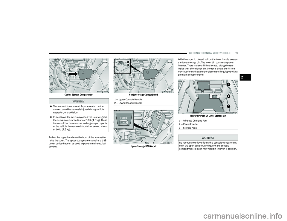
Pull on the upper handle on the front of the armrest to
raise the cover. The upper storage area contains a USB
power outlet that can be used to power small electrical
devices.
Center Storage Compartment
Upper Storage USB Outlet
With the upper lid closed, pull on the lower handle to open
the lower storage bin. The lower bin contains a power
inverter. There is also a fill line located along the rear
inside wall of the lower bin. Contents above the fill line
may interfere with cupholder placement if equipped with a
premium center console.
Forward Portion Of Lower Storage Bin
WARNING!
This armrest is not a seat. Anyone seated on the
armrest could be seriously injured during vehicle
operation, or a collision.
In a collision, the latch may open if the total weight of
the items stored exceeds about 10 lb (4.5 kg). These
items could be thrown about endangering occupants
of the vehicle. Items stored should not exceed a total
of 10 lb (4.5 kg).
1 — Upper Console Handle
2 — Lower Console Handle
1 — Wireless Charging Pad
2 — Power Inverter
3 — Storage Area
WARNING!
Do not operate this vehicle with a console compartment
lid in the open position. Driving with the console
compartment lid open may result in injury in a collision.
2
23_DT_OM_EN_USC_t.book Page 61
Page 64 of 416

62GETTING TO KNOW YOUR VEHICLE
Premium Center Console — If Equipped
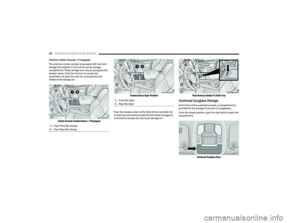
The premium center console is equipped with two front
storage bins located in front of the center storage
compartment. These storage bins may be equipped with
tandem doors. Push the front bin to access the
cupholders. Or push the rear bin to access the coin
holder/small storage bin.
Center Console Tandem Doors— If Equipped Tandem Doors Open Position
Push the release button at the front of the cupholder bin
to slide tray rearward to access the front lower storage bin,
or forward to access the rear lower storage bin.
Push Release Button To Slide Tray
Overhead Sunglass Storage
At the front of the overhead console, a compartment is
provided for the storage of one pair of sunglasses.
From the closed position, push the door latch to open the
compartment.
Overhead Sunglass Door
1 — Push Front Bin Access
2 — Push Rear Bin Access
1 — Front Bin Open
2 — Rear Bin Open
23_DT_OM_EN_USC_t.book Page 62
Page 65 of 416

GETTING TO KNOW YOUR VEHICLE63
Front Bench Seat Storage — If Equipped
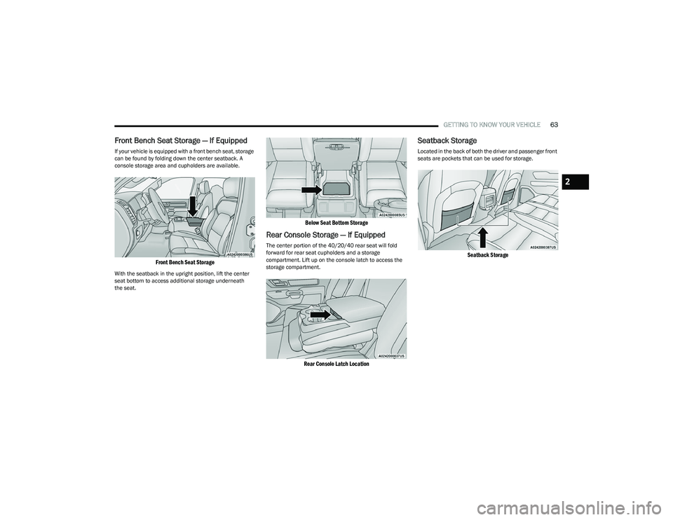
If your vehicle is equipped with a front bench seat, storage
can be found by folding down the center seatback. A
console storage area and cupholders are available.
Front Bench Seat Storage
With the seatback in the upright position, lift the center
seat bottom to access additional storage underneath
the seat.
Below Seat Bottom Storage
Rear Console Storage — If Equipped
The center portion of the 40/20/40 rear seat will fold
forward for rear seat cupholders and a storage
compartment. Lift up on the console latch to access the
storage compartment.
Rear Console Latch Location
Seatback Storage
Located in the back of both the driver and passenger front
seats are pockets that can be used for storage.
Seatback Storage
2
23_DT_OM_EN_USC_t.book Page 63
Page 67 of 416

GETTING TO KNOW YOUR VEHICLE65
Flip the inside of the base upward into the upright position,
locking into place, creating and extended storage area.
Fully Extended Storage Area
NOTE:
The rear seats do not need to be folded up to access this
feature.
USB/AUX CONTROL
Located on the center stack, just below the instrument
panel, is the main media hub. There are four total USB
ports: Two Mini-USBs (Type C) and two Standard USBs
(Type A). There is also an AUX port located in the middle of
the USB ports.
Plugging in a smartphone device to a USB port may
activate Android Auto™ or Apple CarPlay® features, if
equipped. For further information, refer to “Android
Auto™” or “Apple CarPlay®” in the Uconnect Radio
Instruction Manual.
NOTE:Two devices can be plugged in at the same time, and both
ports will provide charging capabilities. Only one port can
transfer data to the system at a time. A pop-up will appear
and allow you to select the device transferring data.
For example, if a device is plugged into the Type A USB port
and another device is plugged into the Type C USB port, a
message will appear and allow you to select which device
to use.
Center Stack USB/AUX Media Hub
The third and fourth USB ports are located behind the
center console, above the power inverter. Both are charge
only.
Rear USB Ports
Applicable to only Uconnect 5/5 NAV With 8.4-inch
Display, and Uconnect 5 NAV With 12-inch Display radios,
different scenarios are listed below when a non-phone
device is plugged into the smaller and larger USB ports,
and when a phone device is plugged into the smaller and
larger USB ports:
“A new device is now connected. Previous connection
was lost”.
“(Phone Name) now connected. Previous connection
was lost”.
“Another device is in use through the same USB port.
Please disconnect the first device to use the second
device”.
1 — Standard USB Type A Port #1
2 — AUX Port
3 — Standard USB Type A Port #2
1 — Rear Charge Only USB Ports 1
2 — Rear Charge Only USB Ports 2
2
23_DT_OM_EN_USC_t.book Page 65
Page 68 of 416

66GETTING TO KNOW YOUR VEHICLE
NOTE:Charge unsupported devices with the Charge Only USB
ports. If an unsupported device is plugged into a Media
USB port, a message will display on the touchscreen that
the device is not supported by the system.
Plugging in a phone or another USB device may cause the
connection to a previous device to be lost.
If equipped, your vehicle may also contain a USB port
located on the top tray of the vehicle’s center console.
If equipped, two Mini-USB ports (Type C), two Standard
USB ports (Type A), and one AUX port may be located to the
left of the center stack, just below the climate controls.
Center Console USB/AUX Media Hub
Some USB ports support media and charging. You can use
features, such as Apple CarPlay®, Android Auto™,
Pandora®, and others while charging your phone.
NOTE:Plugging in a phone or another USB device may cause the
connection to a previous device to be lost.
For further information, refer to the Uconnect Radio
Instruction Manual or visit UconnectPhone.com.
ELECTRICAL POWER OUTLETS
The auxiliary 12 Volt (13 Amp) power outlet can provide
power for in-cab accessories designed for use with the
standard “cigarette lighter” style plug. The 12 Volt power
outlets and 5 Volt (2.5 Amp) USB Port (Charge Only) have
a cap attached to the outlet indicating “12V DC”, together
with either a key symbol, battery symbol, or USB symbol.
An auxiliary power outlet can be found in the tray on top of
the center stack. This power outlet works when the ignition
is in the ON/RUN, ACC, or OFF position.
Power Outlet — Top Of Center Stack
Power Outlet Fuse Locations
1 — Standard USB Type A Ports
2 — Mini-USB Type C Ports
3 — AUX Port
CAUTION!
Do not exceed the maximum power of 160 Watts
(13 Amps) at 12 Volts. If the 160 Watts (13 Amps)
power rating is exceeded, the fuse protecting the
system will need to be replaced.
Power outlets are designed for accessory plugs only.
Do not insert any other object in the power outlets as
this will damage the outlet and blow the fuse.
Improper use of the power outlet can cause damage
not covered by your New Vehicle Limited Warranty.
1 — F54 Fuse 20 A Yellow Power Outlet Battery Fed
Position
2 — F54 Fuse 20 A Yellow Power Outlet Ignition Fed
Position
3 — F48 Fuse 10 A Red Port Power or Rear USB
(Charge Only)
23_DT_OM_EN_USC_t.book Page 66
Page 69 of 416

GETTING TO KNOW YOUR VEHICLE67
(Continued)
When the vehicle is turned off, be sure to unplug any
equipment as to not drain the battery of the vehicle. All
accessories connected to the outlet(s) should be removed
or turned off when the vehicle is not in use to protect the
battery against discharge.
POWER INVERTER — IF EQUIPPED
A 115 Volt (400 Watts maximum) inverter may be located
inside the center console towards the right hand side. This
inverter can power cellular phones, electronics and other
low power devices requiring power up to 400 Watts.
Certain video game consoles exceed this power limit, as
will most power tools.
Center Console Power Inverter Outlet
There is also a second 115 Volt (400 Watts maximum)
power inverter located on the rear of the center console.
This inverter can power cellular phones, electronics and
other low power devices requiring power up to 400 Watts. Certain video game consoles exceed this power limit, as
will most power tools.
All power inverters are designed with built-in overload
protection. If the power rating of 400 Watts is exceeded,
the power inverter shuts down. Once the electrical device
has been removed from the outlet the inverter should
reset.
Rear Center Console Power Inverter Outlet
NOTE:
400 Watts is the maximum for the inverter, not each
outlet. If three outlets are in use, 400 Watts is shared
amongst the devices plugged in.
If equipped with a front bench seat, there may be a
115 Volt (400 Watts maximum) inverter located to the
right of the center stack, just below the climate controls.
This inverter can power cellular phones, electronics and
other low power devices requiring power up to 400 Watts.
WARNING!
To avoid serious injury or death:
Only devices designed for use in this type of outlet
should be inserted into any 12 Volt outlet.
Do not touch with wet hands.
Close the lid when not in use and while driving the
vehicle.
If this outlet is mishandled, it may cause an electric
shock and failure.
CAUTION!
Many accessories that can be plugged in draw power
from the vehicle's battery, even when not in use
(i.e., cellular phones, etc.). Eventually, if plugged in
long enough, the vehicle's battery will discharge suffi -
ciently to degrade battery life and/or prevent the
engine from starting.
Accessories that draw higher power (i.e., coolers,
vacuum cleaners, lights, etc.), will discharge the
battery even more quickly. Only use these intermit -
tently and with greater caution.
After the use of high power draw accessories, or long
periods of the vehicle not being started (with acces -
sories still plugged in), the vehicle must be driven a
sufficient length of time to allow the generator to
recharge the vehicle's battery.
CAUTION!
2
23_DT_OM_EN_USC_t.book Page 67
Page 70 of 416

68GETTING TO KNOW YOUR VEHICLE
Certain video game consoles exceed this power limit, as
will most power tools.
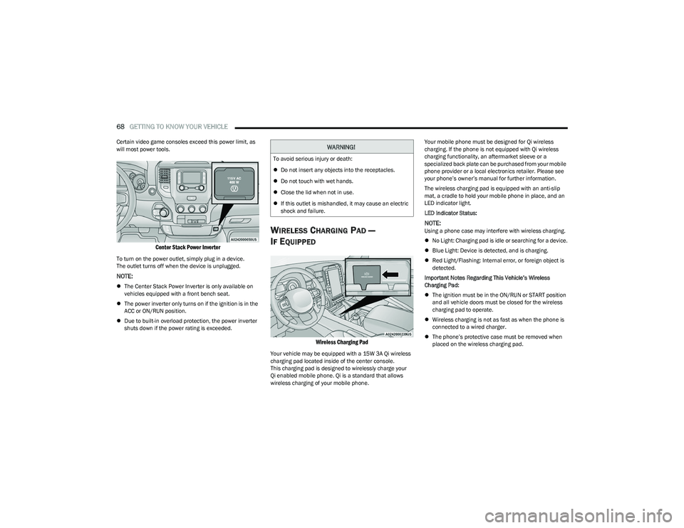
Center Stack Power Inverter
To turn on the power outlet, simply plug in a device.
The outlet turns off when the device is unplugged.
NOTE:
The Center Stack Power Inverter is only available on
vehicles equipped with a front bench seat.
The power inverter only turns on if the ignition is in the
ACC or ON/RUN position.
Due to built-in overload protection, the power inverter
shuts down if the power rating is exceeded.
WIRELESS CHARGING PAD —
I
F EQUIPPED
Wireless Charging Pad
Your vehicle may be equipped with a 15W 3A Qi wireless
charging pad located inside of the center console.
This charging pad is designed to wirelessly charge your
Qi enabled mobile phone. Qi is a standard that allows
wireless charging of your mobile phone. Your mobile phone must be designed for Qi wireless
charging. If the phone is not equipped with Qi wireless
charging functionality, an aftermarket sleeve or a
specialized back plate can be purchased from your mobile
phone provider or a local electronics retailer. Please see
your phone’s owner’s manual for further information.
The wireless charging pad is equipped with an anti-slip
mat, a cradle to hold your mobile phone in place, and an
LED indicator light.
LED Indicator Status:
NOTE:Using a phone case may interfere with wireless charging.
No Light: Charging pad is idle or searching for a device.
Blue Light: Device is detected, and is charging.
Red Light/Flashing: Internal error, or foreign object is
detected.
Important Notes Regarding This Vehicle’s Wireless
Charging Pad:
The ignition must be in the ON/RUN or START position
and all vehicle doors must be closed for the wireless
charging pad to operate.
Wireless charging is not as fast as when the phone is
connected to a wired charger.
The phone’s protective case must be removed when
placed on the wireless charging pad.
WARNING!
To avoid serious injury or death:
Do not insert any objects into the receptacles.
Do not touch with wet hands.
Close the lid when not in use.
If this outlet is mishandled, it may cause an electric
shock and failure.
23_DT_OM_EN_USC_t.book Page 68
Page 73 of 416

GETTING TO KNOW YOUR VEHICLE71
To close the window part way, lift the window switch briefly
and release it when you want the window to stop.
If the window runs into any obstacle during auto-closure, it
will reverse direction and then go back down. Remove the
obstacle and use the window switch again to close the
window.
NOTE:Any impact due to rough road conditions may trigger the
auto-reverse function unexpectedly during auto-closure.
If this happens, pull the switch lightly and hold to close the
window manually.
RESET AUTO-UP
Should the Auto-Up feature stop working, the window
probably needs to be reset. To reset Auto-Up:
1. Pull the window switch up to close the window
completely and continue to hold the switch up for an
additional two seconds after the window is closed.
2. Push the window switch down firmly to open the window completely and continue to hold the switch
down for an additional two seconds after the window
is fully open.
WINDOW LOCKOUT SWITCH
The window lockout switch on the driver's door trim panel
allows you to disable the window controls on the rear
passenger doors. To disable the window controls, push
and release the window lockout button (the indicator light
on the button will turn on). To enable the window controls,
push and release the window lockout button again
(the indicator light on the button will turn off).
Window Lockout Switch
POWER SLIDING REAR WINDOW —
I
F EQUIPPED
The switch for the power sliding rear window is located on
the overhead console. Push the switch rearward to open
the glass. Pull the switch forward to close the glass.
Rear Window Switch
MANUAL SLIDING REAR WINDOW —
I
F EQUIPPED
A locking device in the center of the window helps to
prevent entry from the rear of the vehicle. Squeeze the
lock to release the window.
Manual Rear Window Lock
WARNING!
There is no anti-pinch protection when the window is
almost closed. To avoid personal injury be sure to clear
your arms, hands, fingers and all objects from the
window path before closing.
2
23_DT_OM_EN_USC_t.book Page 71