ECO mode Ram 2500 2018 Owner's Manual
[x] Cancel search | Manufacturer: RAM, Model Year: 2018, Model line: 2500, Model: Ram 2500 2018Pages: 372, PDF Size: 7.1 MB
Page 42 of 372
IconDescription
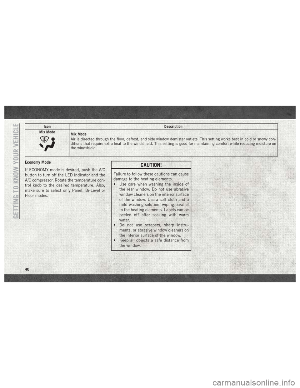
Mix Mode
Mix Mode
Air is directed through the floor, defrost, and side window demister outlets. This setting works best in cold or snowy con-
ditions that require extra heat to the windshield. This setting is good for maintaining comfort while reducing moisture on
the windshield.
Economy Mode
If ECONOMY mode is desired, push the A/C
button to turn off the LED indicator and the
A/C compressor. Rotate the temperature con-
trol knob to the desired temperature. Also,
make sure to select only Panel, Bi-Level or
Floor modes.CAUTION!
Failure to follow these cautions can cause
damage to the heating elements:
• Use care when washing the inside of the rear window. Do not use abrasive
window cleaners on the interior surface
of the window. Use a soft cloth and a
mild washing solution, wiping parallel
to the heating elements. Labels can be
peeled off after soaking with warm
water.
• Do not use scrapers, sharp instru-
ments, or abrasive window cleaners on
the interior surface of the window.
• Keep all objects a safe distance from
the window.
GETTING TO KNOW YOUR VEHICLE
40
Page 45 of 372

Control Descriptions
NOTE:
Icons and descriptions can vary based upon
vehicle equipment.
IconDescription
MAX A/C Button
Press and release to change the current setting, the indicator illuminates when MAX A/C is on. Performing this function
again will cause the MAX A/C operation to switch into manual mode and the MAX A/C indicator will turn off.
A/C Button
Press and release the button on the touchscreen, or push and release the button on the faceplate, to change the current
setting, the indicator illuminates when A/C is on.
Recirculation Button
Press and release this button to change the system between recirculation mode and outside air mode. Recirculation can
be used when outside conditions such as smoke, odors, dust, or high humidity are present.
NOTE:
• Continuous use of the Recirculation mode may make the inside air stuffy and window fogging may occur. Extended
use of this mode is not recommended.
• The use of the Recirculation mode in cold or damp weather could cause windows to fog on the inside, because of
moisture buildup inside the vehicle. Select the outside air position for maximum defogging.
• Recirculation can be used in all modes except for Defrost.
• The A/C can be deselected manually without disturbing the mode control selection.
AUTO Button — If Equipped
Automatically controls the interior cabin temperature by adjusting airflow distribution and amount. Toggling this
function will cause the system to switch between manual mode and automatic modes. Refer to “Automatic Opera-
tion” for more information.
43
Page 48 of 372

IconDescription
Floor Mode
Floor Mode
Air comes from the floor outlets. A slight amount of air is directed through the defrost and side window demister outlets.
Mix ModeMix Mode
Air is directed through the floor, defrost, and side window demister outlets. This setting works best in cold or snowy con-
ditions that require extra heat to the windshield. This setting is good for maintaining comfort while reducing moisture
on the windshield.
Climate Control OFF Button
Press and release this button on the touchscreen, or push the faceplate button, to turn the Climate Control System off.
CAUTION!
Failure to follow these cautions can cause
damage to the heating elements:
•
Use care when washing the inside of the
rear window. Do not use abrasive window
cleaners on the interior surface of the
window. Use a soft cloth and a mild
washing solution, wiping parallel to the
heating elements. Labels can be peeled
off after soaking with warm water.
• Do not use scrapers, sharp instru- ments, or abrasive window cleaners on
the interior surface of the window.
CAUTION!
• Keep all objects a safe distance from
the window.
Climate Control Functions
A/C (Air Conditioning)
The Air Conditioning (A/C) button allows the
operator to manually activate or deactivate
the air conditioning system. When the air
conditioning system is turned on, cool dehu-
midified air will flow through the outlets into
the cabin. For improved fuel economy, press the A/C button to turn off the air conditioning
and manually adjust the blower and airflow
mode settings. Also, make sure to select only
Panel, Bi-Level, or Floor modes.
NOTE:
• If fog or mist appears on the windshield or
side glass, select Defrost mode, and in-
crease blower speed if needed.
• If your air conditioning performance seems lower than expected, check the front of the
A/C condenser (located in front of the ra-
diator), for an accumulation of dirt or in-
GETTING TO KNOW YOUR VEHICLE
46
Page 49 of 372

sects. Clean with a gentle water spray from
the front of the radiator and through the
condenser.
MAX A/C
MAX A/C sets the control for maximum cool-
ing performance.
Press and release to toggle between MAX A/C
and the prior settings. The button illuminates
when MAX A/C is on.
In MAX A/C, the blower level and mode posi-
tion can be adjusted to desired user settings.
Pressing other settings will cause the MAX
A/C operation to switch to the selected set-
ting and MAX A/C to exit.
Recirculation
When outside air contains smoke, odors, or
high humidity, or if rapid cooling is desired,
you may wish to recirculate interior air by
pressing the Recirculation control button.
The Recirculation indicator will illuminate
when this button is selected. Press the button
a second time to turn off the Recirculation
mode and allow outside air into the vehicle. NOTE:
In cold weather, use of Recirculation mode
may lead to excessive window fogging. The
Recirculation feature may be unavailable
(button on the touchscreen greyed out) if
conditions exist that could create fogging on
the inside of the windshield.
Automatic Temperature Control
(ATC) — If Equipped
Automatic Operation
1. Push the AUTO button on the faceplate,
or the AUTO button on the touchscreen on
the Automatic Temperature Control (ATC)
Panel.
2. Next, adjust the temperature you would like the system to maintain by adjusting
the driver and passenger temperature
control buttons. Once the desired tem-
perature is displayed, the system will
achieve and automatically maintain that
comfort level.
3. When the system is set up for your comfort level, it is not necessary to change the settings. You will experience the greatest
efficiency by simply allowing the system
to function automatically.
NOTE:
• It is not necessary to move the temperature settings for cold or hot vehicles. The system
automatically adjusts the temperature,
mode, and blower speed to provide comfort
as quickly as possible.
• The temperature can be displayed in U.S. or Metric units by selecting the US/Metric
customer-programmable feature. Refer to
the “Uconnect Settings” in “Multimedia”
in your Owner’s Manual for further
information.
To provide you with maximum comfort in the
Automatic mode during cold start-ups, the
blower fan will remain on low until the engine
warms up. The blower will increase in speed
and transition into Auto mode.
47
Page 50 of 372

Manual Operation Override
This system offers a full complement of
manual override features. The AUTO symbol
in the front ATC display will be turned off
when the system is being used in the manual
mode.
Operating Tips
Summer Operation
The engine cooling system must be protected
with a high-quality antifreeze coolant to pro-
vide proper corrosion protection and to pro-
tect against engine overheating. OAT coolant
(conforming to MS.90032) is recommended.
Winter Operation
To ensure the best possible heater and de-
froster performance, make sure the engine
cooling system is functioning properly and
the proper amount, type, and concentration
of coolant is used. Use of the Air Recircula-
tion mode during Winter months is not rec-
ommended, because it may cause window
fogging.
Vacation/Storage
Before you store your vehicle, or keep it out of
service (i.e., vacation) for two weeks or more,
run the air conditioning system at idle for
about five minutes, in fresh air with the
blower setting on high. This will ensure ad-
equate system lubrication to minimize the
possibility of compressor damage when the
system is started again.
Window Fogging
Vehicle windows tend to fog on the inside in
mild, rainy, and/or humid weather. To clear
the windows, select Defrost or Mix mode and
increase the front blower speed. Do not use
the Recirculation mode without A/C for long
periods, as fogging may occur.
Outside Air Intake
Make sure the air intake, located directly in
front of the windshield, is free of obstruc-
tions, such as leaves. Leaves collected in the
air intake may reduce airflow, and if they
enter the plenum, they could plug the water
drains. In Winter months, make sure the air
intake is clear of ice, slush, and snow.
Cabin Air Filter
The climate control system filters out dust
and pollen from the air. Contact an autho-
rized dealer to service your cabin air filter,
and to have it replaced when needed.
GETTING TO KNOW YOUR VEHICLE
48
Page 51 of 372
POWER SUNROOF — IF EQUIPPED
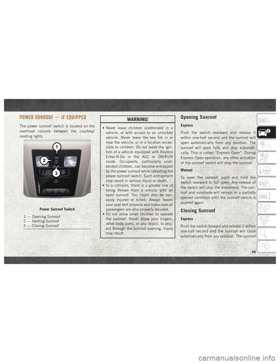
The power sunroof switch is located on the
overhead console between the courtesy/
reading lights.
WARNING!
• Never leave children unattended in avehicle, or with access to an unlocked
vehicle. Never leave the key fob in or
near the vehicle, or in a location acces-
sible to children. Do not leave the igni-
tion of a vehicle equipped with Keyless
Enter-N-Go in the ACC or ON/RUN
mode. Occupants, particularly unat-
tended children, can become entrapped
by the power sunroof while operating the
power sunroof switch. Such entrapment
may result in serious injury or death.
• In a collision, there is a greater risk of
being thrown from a vehicle with an
open sunroof. You could also be seri-
ously injured or killed. Always fasten
your seat belt properly and make sure all
passengers are also properly secured.
• Do not allow small children to operate
the sunroof. Never allow your fingers,
other body parts, or any object, to proj-
ect through the sunroof opening. Injury
may result.
Opening Sunroof
Express
Push the switch rearward and release it
within one-half second and the sunroof will
open automatically from any position. The
sunroof will open fully and stop automati-
cally. This is called “Express Open”. During
Express Open operation, any other actuation
of the sunroof switch will stop the sunroof.
Manual
To open the sunroof, push and hold the
switch rearward to full open. Any release of
the switch will stop the movement. The sun-
roof and sunshade will remain in a partially
opened condition until the sunroof switch is
pushed again.
Closing Sunroof
Express
Push the switch forward and release it within
one-half second and the sunroof will close
automatically from any position. The sunroof
Power Sunroof Switch
1 — Opening Sunroof
2 — Venting Sunroof
3 — Closing Sunroof
49
Page 52 of 372
will close fully and stop automatically. This is
called “Express Close”. During Express Close
operation, any other actuation of the switch
will stop the sunroof.
Manual
To close the sunroof, push and hold the
switch in the forward position. Any release of
the switch will stop the movement and the
sunroof will remain in a partially closed con-
dition until the sunroof switch is pushed
again.
Wind Buffeting
Wind buffeting can be described as the per-
ception of pressure on the ears or a
helicopter-type sound in the ears. Your ve-
hicle may exhibit wind buffeting with the
windows down, or the sunroof (if equipped) in
certain open or partially open positions. This
is a normal occurrence and can be mini-
mized. If the buffeting occurs with the rear
windows open, then open the front and rear
windows together to minimize the buffeting.
If the buffeting occurs with the sunroof open,
adjust the sunroof opening to minimize the
buffeting or open any window.
Pinch Protect Feature
This feature will detect an obstruction in the
closing of the sunroof during the Express
Close operation. If an obstruction in the path
of the sunroof is detected, the sunroof will
automatically retract. Remove the obstruc-
tion if this occurs.
NOTE:
If three consecutive sunroof close attempts
result in Pinch Protect reversals, Pinch Pro-
tect will disable and the sunroof must be
closed in Manual Mode.
Venting Sunroof — Express
Push and release the Vent button within one
half second and the sunroof will open to the
vent position. This is called “Express Vent”
and it will occur regardless of sunroof posi-
tion. During Express Vent operation, any
movement of the switch will stop the sunroof.
HOOD
To Open The Hood
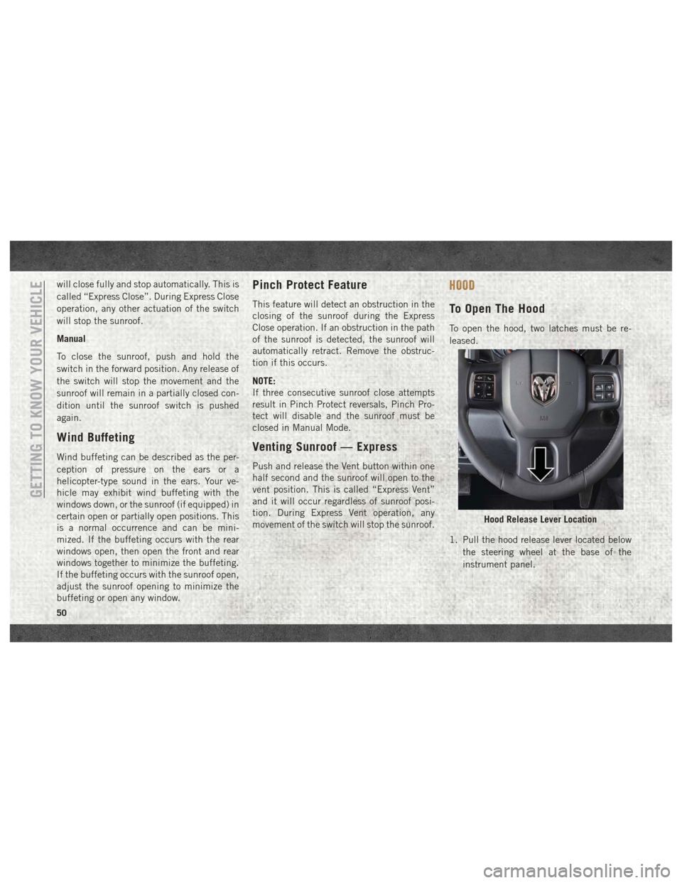
To open the hood, two latches must be re-
leased.
1. Pull the hood release lever located belowthe steering wheel at the base of the
instrument panel.
Hood Release Lever Location
GETTING TO KNOW YOUR VEHICLE
50
Page 68 of 372
INSTRUMENT CLUSTER DISPLAY
Your vehicle may be equipped with an instru-
ment cluster display, which offers useful in-
formation to the driver. With the ignition in
the STOP/OFF mode, opening/closing of a
door will activate the display for viewing, and
display the total miles, or kilometers, in the
odometer. Your instrument cluster display is
designed to display important information
about your vehicle’s systems and features.
Using a driver interactive display located on
the instrument panel, your instrument clus-
ter display can show you how systems are
working and give you warnings when they are
not. The steering wheel mounted controls
allow you to scroll through the main menus
and submenus. You can access the specific
information you want and make selections
and adjustments.
Instrument Cluster Display
Controls
The instrument cluster display features a
driver-interactive display that is located in
the instrument cluster.
The instrument cluster display menu items
may consist of the following:
• Speedometer
• Vehicle Info
• Fuel Economy Info
• Trip A
• Trip B
• Audio
• Trailer Tow
• Stored Messages
• Screen Setup
• Vehicle Settings (Not Equipped with aUconnect touchscreen radio) The system allows the driver to select infor-
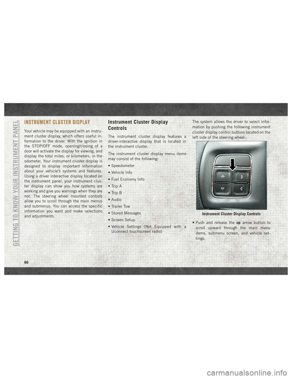
mation by pushing the following instrument
cluster display control buttons located on the
left side of the steering wheel:
• Push and release the
uparrow button to
scroll upward through the main menu
items, submenu screen, and vehicle set-
tings.
Instrument Cluster Display Controls
GETTING TO KNOW YOUR INSTRUMENT PANEL
66
Page 86 of 372
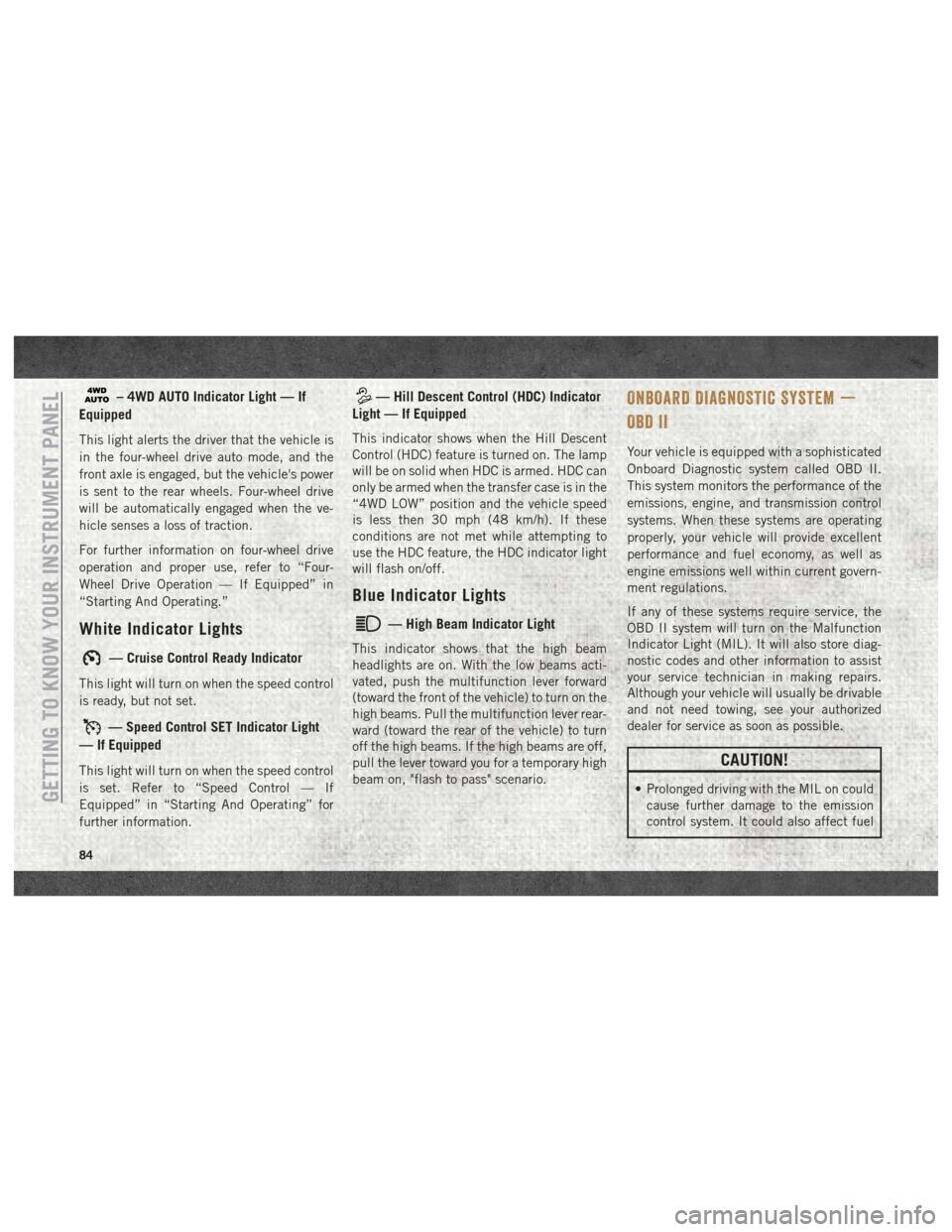
– 4WD AUTO Indicator Light — If
Equipped
This light alerts the driver that the vehicle is
in the four-wheel drive auto mode, and the
front axle is engaged, but the vehicle's power
is sent to the rear wheels. Four-wheel drive
will be automatically engaged when the ve-
hicle senses a loss of traction.
For further information on four-wheel drive
operation and proper use, refer to “Four-
Wheel Drive Operation — If Equipped” in
“Starting And Operating.”
White Indicator Lights
— Cruise Control Ready Indicator
This light will turn on when the speed control
is ready, but not set.
— Speed Control SET Indicator Light
— If Equipped
This light will turn on when the speed control
is set. Refer to “Speed Control — If
Equipped” in “Starting And Operating” for
further information.
— Hill Descent Control (HDC) Indicator
Light — If Equipped
This indicator shows when the Hill Descent
Control (HDC) feature is turned on. The lamp
will be on solid when HDC is armed. HDC can
only be armed when the transfer case is in the
“4WD LOW” position and the vehicle speed
is less then 30 mph (48 km/h). If these
conditions are not met while attempting to
use the HDC feature, the HDC indicator light
will flash on/off.
Blue Indicator Lights
— High Beam Indicator Light
This indicator shows that the high beam
headlights are on. With the low beams acti-
vated, push the multifunction lever forward
(toward the front of the vehicle) to turn on the
high beams. Pull the multifunction lever rear-
ward (toward the rear of the vehicle) to turn
off the high beams. If the high beams are off,
pull the lever toward you for a temporary high
beam on, "flash to pass" scenario.
ONBOARD DIAGNOSTIC SYSTEM —
OBD II
Your vehicle is equipped with a sophisticated
Onboard Diagnostic system called OBD II.
This system monitors the performance of the
emissions, engine, and transmission control
systems. When these systems are operating
properly, your vehicle will provide excellent
performance and fuel economy, as well as
engine emissions well within current govern-
ment regulations.
If any of these systems require service, the
OBD II system will turn on the Malfunction
Indicator Light (MIL). It will also store diag-
nostic codes and other information to assist
your service technician in making repairs.
Although your vehicle will usually be drivable
and not need towing, see your authorized
dealer for service as soon as possible.
CAUTION!
• Prolonged driving with the MIL on could
cause further damage to the emission
control system. It could also affect fuelGETTING TO KNOW YOUR INSTRUMENT PANEL
84
Page 106 of 372
WARNING!
• Failure to replace the seat belt assemblycould increase the risk of injury in colli-
sions.
• Do not use the Automatic Locking Mode
to restrain occupants who are wearing
the seat belt or children who are using
booster seats. The locked mode is only
used to install rear-facing or forward-
facing child restraints that have a har-
ness for restraining the child.
Supplemental Restraint Systems
(SRS)
Some of the safety features described in this
section may be standard equipment on some
models, or may be optional equipment on
others. If you are not sure, ask your autho-
rized dealer.
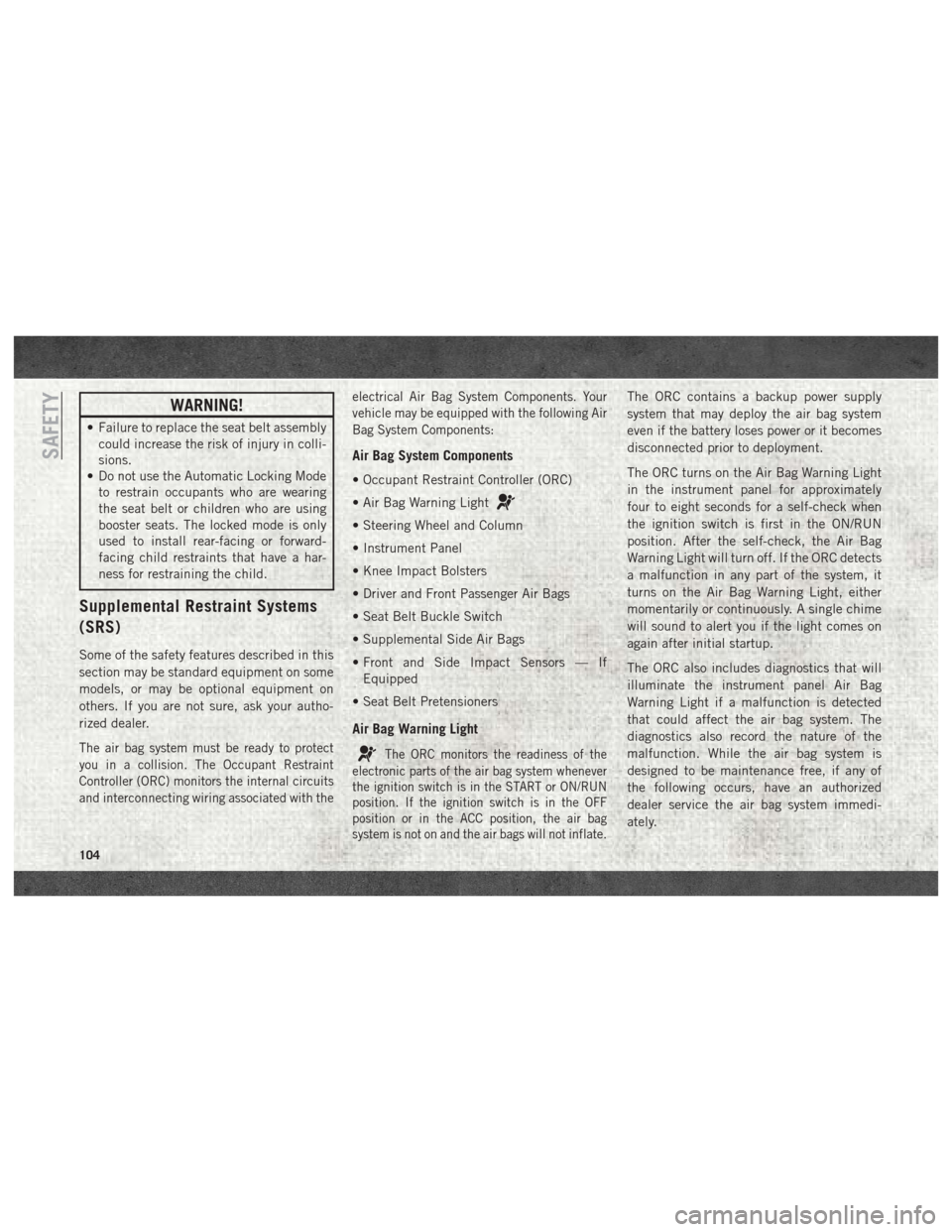
The air bag system must be ready to protect
you in a collision. The Occupant Restraint
Controller (ORC) monitors the internal circuits
and interconnecting wiring associated with the electrical Air Bag System Components. Your
vehicle may be equipped with the following Air
Bag System Components:
Air Bag System Components
• Occupant Restraint Controller (ORC)
• Air Bag Warning Light
• Steering Wheel and Column
• Instrument Panel
• Knee Impact Bolsters
• Driver and Front Passenger Air Bags
• Seat Belt Buckle Switch
• Supplemental Side Air Bags
• Front and Side Impact Sensors — If
Equipped
• Seat Belt Pretensioners
Air Bag Warning Light
The ORC monitors the readiness of the
electronic parts of the air bag system whenever
the ignition switch is in the START or ON/RUN
position. If the ignition switch is in the OFF
position or in the ACC position, the air bag
system is not on and the air bags will not inflate.
The ORC contains a backup power supply
system that may deploy the air bag system
even if the battery loses power or it becomes
disconnected prior to deployment.
The ORC turns on the Air Bag Warning Light
in the instrument panel for approximately
four to eight seconds for a self-check when
the ignition switch is first in the ON/RUN
position. After the self-check, the Air Bag
Warning Light will turn off. If the ORC detects
a malfunction in any part of the system, it
turns on the Air Bag Warning Light, either
momentarily or continuously. A single chime
will sound to alert you if the light comes on
again after initial startup.
The ORC also includes diagnostics that will
illuminate the instrument panel Air Bag
Warning Light if a malfunction is detected
that could affect the air bag system. The
diagnostics also record the nature of the
malfunction. While the air bag system is
designed to be maintenance free, if any of
the following occurs, have an authorized
dealer service the air bag system immedi-
ately.
SAFETY
104