ECO mode Ram 2500 2018 Owner's Guide
[x] Cancel search | Manufacturer: RAM, Model Year: 2018, Model line: 2500, Model: Ram 2500 2018Pages: 372, PDF Size: 7.1 MB
Page 149 of 372
cally crank when the "Wait To Start" time
has elapsed. See the section "Starting Pro-
cedure Engine Manifold Air Temperature
0°F to 66°F (18° C to 19°C)" in the Diesel
Supplement for more information.
To Turn Off The Engine Using ENGINE START/
STOP Button
1. Place the gear selector in PARK, then push and release the ENGINE START/
STOP button.
2. The ignition will return to the OFF mode.
3. If the gear selector is not in PARK and the ENGINE START/STOP button is pushed
once, the instrument cluster will display a
“Vehicle Not In Park” message and the
engine will remain running. Never leave a
vehicle out of the PARK position, or it
could roll.
4. If the gear selector is in NEUTRAL, and the vehicle speed below 5 mph (8 km/h),
pushing the START/STOP button once will
turn the engine off. The ignition will re-
main in the ACC mode.
5.
If the vehicle speed is above 5 mph (8 km/h),
the ENGINE START/STOP button must be held for two seconds (or three short pushes
in a row) to turn the engine off. The ignition
will remain in the ACC mode (NOT the OFF
mode) if the engine is turned off when the
transmission is not in PARK.
NOTE:
If the ignition is left in the ACC or ON/RUN
(engine not running) mode and the transmis-
sion is in PARK, the system will automatically
time out after 30 minutes of inactivity and
the ignition return to the OFF mode.
ENGINE START/STOP Button Functions — With
Driver’s Foot OFF The Brake Pedal (In PARK Or
NEUTRAL Position)
The ENGINE START/STOP button operates
similar to an ignition switch. It has three
positions, OFF, ACC, RUN. To change the
ignition switch positions without starting the
vehicle and use the accessories follow these
steps:
1. Starting with the ignition in the OFF
position:
2. Push the ENGINE START/STOP button once to change the ignition to the ACC
position. 3. Push the ENGINE START/STOP button a
second time to change the ignition to the
RUN position.
4. Push the ENGINE START/STOP button a third time to return the ignition to the OFF
position.
Keyless Enter-N-Go Starting Procedure —
Engine Manifold Air Temperature 0° F To
66° F (–18° C to 19° C)
NOTE:
The temperature displayed in the instrument
cluster does not necessarily reflect the en-
gine manifold air temperature. Refer to “In-
strument Cluster Display” in “Getting To
Know Your Instrument Panel” for further in-
formation. When engine temperatures fall
below 66°F (19°C) the “Wait To Start Light”
will remain on indicating the intake manifold
heater system is active.
Follow the steps in the “Normal Starting”
procedure except:
1. Pushing the engine start button with thedriver’s foot on the brake will move the
147
Page 155 of 372
Driving ConditionLoadTurbocharger Temperature Idle Time (min.) Before Engine Shut-
down
Stop and Go EmptyCoolLess than One
Stop and Go Medium -One
Highway Speeds MediumWarmTwo
City Traffic Maximum GCWR -Three
Highway Speeds Maximum GCWR -Four
Uphill Grade Maximum GCWR HotFive
ENGINE BREAK-IN
RECOMMENDATIONS — GASOLINE
ENGINE
A long break-in period is not required for the
engine and drivetrain (transmission and axle)
in your vehicle.
Drive moderately during the first 300 miles
(500 km). After the initial 60 miles
(100 km), speeds up to 50 or 55 mph (80 or
90 km/h) are desirable.
While cruising, brief full-throttle acceleration
within the limits of local traffic laws contrib-
utes to a good break-in. Wide-open throttle
acceleration in low gear can be detrimental
and should be avoided. The engine oil installed in the engine at the
factory is a high-quality energy conserving
type lubricant. Oil changes should be consis-
tent with anticipated climate conditions un-
der which vehicle operations will occur. For
the recommended viscosity and quality
grades, refer to “Fluids And Lubricants” in
“Technical Specifications”.
CAUTION!
Never use Non-Detergent Oil or Straight
Mineral Oil in the engine or damage may
result.
NOTE:
A new engine may consume some oil during
its first few thousand miles (kilometers) of
operation. This should be considered a nor-
mal part of the break-in and not interpreted
as a problem. Please check your oil level with
the engine oil indicator often during the
break in period. Add oil as required.
153
Page 159 of 372

control. Pressing the GEAR-/GEAR+ switches
(on the steering wheel) while in the DRIVE
position will select the highest available
transmission gear, and will display that gear
limit in the instrument cluster as 1, 2, 3, etc.
Refer to “Electronic Range Select (ERS) Op-
eration” in this section for further informa-
tion. Some models will display both the se-
lected gear limit, and the actual current gear,
while in ERS mode.Transmission Limp Home Mode
Transmission function is monitored electroni-
cally for abnormal conditions. If a condition
is detected that could result in transmission
damage, Transmission Limp Home Mode is
activated. In this mode, the transmission may
operate only in certain gears, or may not shift
at all. Vehicle performance may be severely
degraded and the engine may stall. In some
situations, the transmission may not re-
engage if the engine is turned off and re-
started. The Malfunction Indicator Light
(MIL) may be illuminated. A message in the
instrument cluster will inform the driver of
the more serious conditions, and indicate
what actions may be necessary.
In the event of a momentary problem, the
transmission can be reset to regain all for-
ward gears by performing the following steps:
NOTE:
In cases where the instrument cluster mes-
sage indicates the transmission may not re-
engage after engine shutdown, perform this
procedure only in a desired location (prefer-
ably, at your authorized dealer).1. Stop the vehicle.
2. Shift the transmission into PARK, if pos-
sible. If not, shift the transmission to
NEUTRAL.
3. Turn the ignition to the OFF position. On vehicles with Keyless Enter-N-Go, push
and hold the ignition switch until the
engine turns OFF.
4. Wait approximately 30 seconds.
5. Restart the engine.
6. Shift into the desired gear range. If the problem is no longer detected, the trans-
mission will return to normal operation.
NOTE:
Even if the transmission can be reset, we
recommend that you visit your authorized
dealer at your earliest possible convenience.
Your authorized dealer has diagnostic equip-
ment to assess the condition of your trans-
mission.
If the transmission cannot be reset, autho-
rized dealer service is required.
Electronic Transmission Gear Selector
157
Page 161 of 372
Only shift from DRIVE to PARK or REVERSE
when the accelerator pedal is released and
the vehicle is stopped. Be sure to keep your
foot on the brake pedal when shifting be-
tween these gears.
The transmission gear selector has only
PARK, REVERSE, NEUTRAL, and DRIVE
shift positions. Manual downshifts can be
made using the Electronic Range Select
(ERS) shift control. Pressing the ERS (-/+)
switches (column shift) or moving the gear
selector to the left or right (-/+) (console shift)
while in the DRIVE position will select the
highest available transmission gear, and will
display that gear limit in the instrument clus-
ter as 1, 2, 3, etc. Refer to "Electronic Range
Select (ERS) Operation" in this section for
further information. Some models will dis-
play both the selected gear limit, and the
actual current gear, while in ERS mode.Transmission Limp Home Mode
Transmission function is monitored electroni-
cally for abnormal conditions. If a condition is
detected that could result in transmission
damage, Transmission Limp Home Mode is
activated. In this mode, the transmission re-
mains in direct gear regardless of which for-
ward gear is selected. PARK, REVERSE, and
NEUTRAL will continue to operate. The Mal-
function Indicator Light (MIL) may be illumi-
nated. Limp Home Mode allows the vehicle to
be driven to an authorized dealer for service
without damaging the transmission.
In the event of a momentary problem, the
transmission can be reset to regain all for-
ward gears by performing the following steps:
1. Stop the vehicle.
2. Shift the transmission into PARK.
3. Turn the ignition OFF.
4. Wait approximately 10 seconds.
5. Restart the engine.
6. Shift into the desired gear range. If theproblem is no longer detected, the trans-
mission will return to normal operation. NOTE:
Even if the transmission can be reset, we
recommend that you visit your authorized
dealer at your earliest possible convenience.
Your authorized dealer has diagnostic equip-
ment to assess the condition of your trans-
mission.
If the transmission cannot be reset, autho-
rized dealer service is required.
Electronic Range Select (ERS) Operation —
Six-Speed Transmission (1500 Models
Only)
The Electronic Range Select (ERS) shift con-
trol allows the driver to limit the highest
available gear when the transmission is in
DRIVE. For example, if you set the transmis-
sion gear limit to 4 (fourth gear), the trans-
mission will not shift above fourth gear, but
will shift through the lower gears normally.
Use of ERS (or TOW/HAUL mode) also en-
ables an additional underdrive gear which is
not normally used during through-gear accel-
erations. This additional gear can improve
vehicle performance and cooling capability
when towing a trailer on certain grades. In
159
Page 163 of 372
drive, move the gear selector from PARK or
NEUTRAL to the DRIVE position. Pull the
gear selector toward you when shifting into
REVERSE or PARK, or when shifting out of
PARK.
The electronically-controlled transmission
provides a precise shift schedule. The trans-
mission electronics are self-calibrating;
therefore, the first few shifts on a new vehicle
may be somewhat abrupt. This is a normal
condition, and precision shifts will develop
within a few hundred miles (kilometers).
Only shift from DRIVE to PARK or REVERSE
when the accelerator pedal is released and
the vehicle is stopped. Be sure to keep your
foot on the brake pedal when shifting be-
tween these gears.
The transmission gear selector has only
PARK, REVERSE, NEUTRAL, and DRIVE
shift positions. Manual downshifts can be
made using the Electronic Range Select
(ERS) shift control. Pressing the ERS (-/+)
switches (on the gear selector) while in the
DRIVE position will select the highest avail-
able transmission gear, and will display that
gear limit in the instrument cluster as 1, 2, 3,etc. Refer to "Electronic Range Select (ERS)
Operation" in this section for further informa-
tion. Some models will display both the se-
lected gear limit, and the actual current gear,
while in ERS mode.
Transmission Limp Home Mode
Transmission function is monitored electroni-
cally for abnormal conditions. If a condition
is detected that could result in transmission
damage, Transmission Limp Home Mode is
activated. In this mode, the transmission
remains in fourth gear regardless of which
forward gear is selected. PARK, REVERSE,
and NEUTRAL will continue to operate. The
Malfunction Indicator Light (MIL) may be
illuminated. Limp Home Mode allows the
vehicle to be driven to an authorized dealer
for service without damaging the transmis-
sion.
In the event of a momentary problem, the
transmission can be reset to regain all for-
ward gears by performing the following steps:
1. Stop the vehicle.
2. Shift the transmission into PARK.
3. Turn the ignition OFF.4. Wait approximately 10 seconds.
5. Restart the engine.
6. Shift into the desired gear range. If the
problem is no longer detected, the trans-
mission will return to normal operation.
NOTE:
Even if the transmission can be reset, we
recommend that you visit your authorized
dealer at your earliest possible convenience.
Your authorized dealer has diagnostic equip-
ment to assess the condition of your trans-
mission.
If the transmission cannot be reset, autho-
rized dealer service is required.
Electronic Range Select (ERS) Operation
The Electronic Range Select (ERS) shift con-
trol allows the driver to limit the highest
available gear when the transmission is in
DRIVE. For example, if you set the transmis-
sion gear limit to 4 (fourth gear), the trans-
mission will not shift above fourth gear, but
will shift through the lower gears normally.
161
Page 167 of 372
4WD LOCK
Four-Wheel Drive Lock High Range — This
range maximizes torque to the front drive-
shaft, forcing the front and rear wheels to
rotate at the same speed. Additional traction
for loose, slippery road surfaces only.
4WD LOW
Four-Wheel Drive Low Range — This range
provides low speed four-wheel drive. It maxi-
mizes torque to the front driveshaft, forcing
the front and rear wheels to rotate at the same
speed. This range provides additional trac-
tion and maximum pulling power for loose,
slippery road surfaces only. Do not exceed
25 mph (40 km/h).
NEUTRAL (N)
Neutral — This range disengages both the
front and rear driveshafts from the pow-
ertrain. To be used for flat towing behind
another vehicle. Refer to “Recreational Tow-
ing” in this section for further information.This electronically shifted transfer case is
designed to be driven in the two-wheel drive
position (2WD) or four-wheel drive position
(4WD AUTO) for normal street and highway
conditions on dry hard surfaced roads). Driv-
ing the vehicle in 2WD will have greater fuel
economy benefits as the front axle is not
engaged in 2WD.
For variable driving conditions, the 4WD
AUTO mode can be used. In this mode, the
front axle is engaged, but the vehicle's power
is sent to the rear wheels. Four-wheel drive
will be automatically engaged when the ve-
hicle senses a loss of traction. Because the
front axle is engaged, this mode will result in
lower fuel economy than the 2WD mode.
When additional traction is required, the
transfer case 4WD LOCK and 4WD LOW po-
sitions can be used to maximize torque to the
front driveshaft, forcing the front and rear
wheels to rotate at the same speed. This is
accomplished by rotating the 4WD Control
Switch to the desired position.Refer to “Shifting Procedure” in the “Start-
ing And Operating” section of you Owner’s
Manual for specific shifting instructions.
WARNING!
You or others could be injured or killed if
you leave the vehicle unattended with the
transfer case in the NEUTRAL position
without first fully engaging the parking
brake. The transfer case NEUTRAL posi-
tion disengages both the front and rear
drive shafts from the powertrain and will
allow the vehicle to roll, even if the trans-
mission is in PARK. The parking brake
should always be applied when the driver
is not in the vehicle.
165
Page 171 of 372
4WD LOCK
Four-Wheel Drive Lock High Range — This
range maximizes torque to the front drive-
shaft, forcing the front and rear wheels to
rotate at the same speed. Additional traction
for loose, slippery road surfaces only.
4WD LOW
Four-Wheel Drive Low Range — This range
provides low speed four-wheel drive. It maxi-
mizes torque to the front driveshaft, forcing
the front and rear wheels to rotate at the same
speed. This range provides additional trac-
tion and maximum pulling power for loose,
slippery road surfaces only. Do not exceed
25 mph (40 km/h).
NEUTRAL (N)
Neutral — This range disengages both the
front and rear driveshafts from the pow-
ertrain. To be used for flat towing behind
another vehicle. Refer to “Recreational Tow-
ing” in this section for further information.
This electronically shifted transfer case is
designed to be driven in the two–wheel drive
position (2WD) or four-wheel drive position
(4WD AUTO) for normal street and highwayconditions on dry hard surfaced roads). Driv-
ing the vehicle in 2WD will have greater fuel
economy benefits as the front axle is not
engaged in 2WD.
For variable driving conditions, the 4WD
AUTO mode can be used. In this mode, the
front axle is engaged, but the vehicle's power
is sent to the rear wheels. Four-wheel drive
will be automatically engaged when the ve-
hicle senses a loss of traction. Because the
front axle is engaged, this mode will result in
lower fuel economy than the 2WD mode.
When additional traction is required, the
transfer case 4WD LOCK and 4WD LOW po-
sitions can be used to maximize torque to the
front driveshaft, forcing the front and rear
wheels to rotate at the same speed. This is
accomplished pushing the desired position
on the 4WD Control Switch.
Refer to “Shifting Procedure” in the “Start-
ing And Operating” section of your Owner’s
Manual for further details.WARNING!
• You or others could be injured or killed if
you leave the vehicle unattended with
the transfer case in the NEUTRAL (N)
position without first fully engaging the
parking brake. The transfer case NEU-
TRAL (N) position disengages both the
front and rear drive shaft from the pow-
ertrain, and will allow the vehicle to roll,
even if the automatic transmission is in
PARK (or manual transmission is in
gear). The parking brake should always
be applied when the driver is not in the
vehicle.
• The transmission may not engage PARK
if the vehicle is moving. Always bring the
vehicle to a complete stop before shift-
ing to PARK, and verify that the trans-
mission gear position indicator solidly
indicates PARK (P) without blinking. En-
sure that the vehicle is completely
stopped, and the PARK position is prop-
erly indicated, before exiting the ve-
hicle.
169
Page 172 of 372
AIR SUSPENSION SYSTEM
(1500 MODELS) — IF EQUIPPED
Description
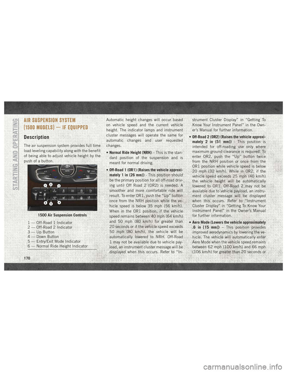
The air suspension system provides full time
load leveling capability along with the benefit
of being able to adjust vehicle height by the
push of a button.Automatic height changes will occur based
on vehicle speed and the current vehicle
height. The indicator lamps and instrument
cluster messages will operate the same for
automatic changes and user requested
changes.
•
Normal Ride Height (NRH) – This is the stan-
dard position of the suspension and is
meant for normal driving.
• Off-Road 1 (OR1) (Raises the vehicle approxi-
mately 1 in (26 mm)) - This position should
be the primary position for all off-road driv-
ing until Off Road 2 (OR2) is needed. A
smoother and more comfortable ride will
result. To enter OR1, push the “Up” button
once from the NRH position while the ve-
hicle speed is below 35 mph (56 km/h).
When in the OR1 position, if the vehicle
speed remains between 40 mph (64 km/h)
and 50 mph (80 km/h) for greater than
20 seconds or if the vehicle speed exceeds
50 mph (80 km/h), the vehicle will be
automatically lowered to NRH. Off-Road
1 may not be available due to vehicle pay-
load, an instrument cluster message will be
displayed when this occurs. Refer to “In- strument Cluster Display” in “Getting To
Know Your Instrument Panel” in the Own-
er’s Manual for further information.
• Off-Road 2 (OR2) (Raises the vehicle approxi-
mately 2 in (51 mm)) - This position is
intended for off-roading use only where
maximum ground clearance is required. To
enter OR2, push the “Up” button twice
from the NRH position or once from the
OR1 position while vehicle speed is below
20 mph (32 km/h). While in OR2, if the
vehicle speed exceeds 25 mph (40 km/h)
the vehicle height will be automatically
lowered to OR1. Off-Road 2 may not be
available due to vehicle payload, an instru-
ment cluster message will be displayed
when this occurs. Refer to “Instrument
Cluster Display” in “Getting To Know Your
Instrument Panel” in the Owner’s Manual
for further information.
• Aero Mode (Lowers the vehicle approximately
.6 in [15 mm]) – This position provides
improved aerodynamics by lowering the ve-
hicle. The vehicle will automatically enter
Aero Mode when the vehicle speed remains
between 62 mph (100 km/h) and 66 mph
(106 km/h) for greater than 20 seconds or
1500 Air Suspension Controls
1 — Off-Road 1 Indicator
2 — Off-Road 2 Indicator
3 — Up Button
4 — Down Button
5 — Entry/Exit Mode Indicator
6 — Normal Ride Height Indicator
STARTING AND OPERATING
170
Page 173 of 372
if the vehicle speed exceeds 66 mph
(106 km/h). The vehicle will return to NRH
from Aero Mode if the vehicle speed re-
mains between 30 mph (48 km/h) and
35 mph (56 km/h) for greater than 20 sec-
onds or if the vehicle speed falls below
30 mph (48 km/h).
NOTE:
Automatic Aero Mode may be disabled
through vehicle settings in the instrument
cluster when equipped with Uconnect 3.0, or
your Uconnect Radio when equipped with
Uconnect 5.0, 8.4A, or 8.4AN.
• Entry/Exit Mode (Lowers the vehicle approxi-
mately 2 in (51 mm)) - This position lowers
the vehicle for easier passenger entry and
exit as well as lowering the rear of the
vehicle for easier loading and unloading of
cargo. To enter Entry/Exit Mode, push the
“Down” button once from the NHR while
the vehicle speed is below 33 mph (53 km/
h). Once the vehicle speed goes below
15 mph (24 km/h) the vehicle height will
begin to lower. If the vehicle speed remains
between 15 mph (24 km/h) and 25 mph
(40 km/h) for greater than 60 seconds, or the vehicle speed exceeds 25 mph
(40 km/h) the Entry/Exit change will be
cancelled. To return to Normal Height
Mode, push the “Up” button once while in
Entry/Exit or drive the vehicle over 15 mph
(24 km/h). Entry/Exit mode may not be
available due to vehicle payload, an instru-
ment cluster message will be displayed
when this occurs. Refer to “Instrument
Cluster Display” in “Getting To Know Your
Instrument Panel” in the Owner’s Manual
for further information.
Air Suspension Modes
The Air Suspension system has multiple
modes to protect the system in unique situa-
tions:
AERO Mode
To improve aerodynamics, the air suspension
system has a feature which will put the ve-
hicle into AERO height automatically. Refer
to “Instrument Cluster Display” in “Getting
To Know Your Instrument Panel” in the Own-
er’s Manual for further information.
NOTE:
This mode is intended to be enabled with
engine running.
Tire/Jack Mode
To assist with changing a tire, the air suspen-
sion system has a feature which allows the
automatic leveling to be disabled. Refer to
“Instrument Cluster Display” in “Getting To
Know Your Instrument Panel” in the Owner’s
Manual for further information.
NOTE:
This mode is intended to be enabled with
engine running.
Transport Mode
For towing your vehicle with four wheels off
the ground, the air suspension system has a
feature which will put the vehicle into Entry/
Exit height and disable the automatic load
leveling system. Refer to “Instrument Cluster
Display” in “Getting To Know Your Instru-
ment Panel” in the Owner’s Manual for fur-
ther information.
171
Page 174 of 372
NOTE:
This mode is intended to be enabled with
engine running.
Wheel Alignment Mode
Before performing a wheel alignment, this
mode must be enabled. Refer to “Instrument
Cluster Display” in “Getting To Know Your
Instrument Panel” in the Owner’s Manual for
further information.
NOTE:
This mode is intended to be enabled with
engine running.
Protection Strategy
In order to “protect” the air suspension sys-
tem, the vehicle will disable load leveling as
required (suspension overloaded, battery
charge low, etc.). Load leveling will automati-
cally resume as soon as system operation
requirements are met. See your authorized
dealer if system does not resume.
NOTE:
If towing with air suspension refer to “Trailer
Towing” in “Starting And Operating” for fur-
ther information.AIR SUSPENSION SYSTEM (REBEL
MODELS ONLY) — IF EQUIPPED
Description
The air suspension system provides full time
load leveling capability along with the benefit
of being able to adjust vehicle height by the
push of a button.
Automatic height changes will occur based
on vehicle speed and the current vehicle
height. The indicator lamps and instrument
cluster messages will operate the same for
automatic changes and user requested
changes.NOTE:
The vehicle will automatically enter Aero Mode
when the vehicle speed remains between
62 mph (100 km/h) and 66 mph (106 km/h)
for greater than 20 seconds or if the vehicle
speed exceeds 66 mph (106 km/h).
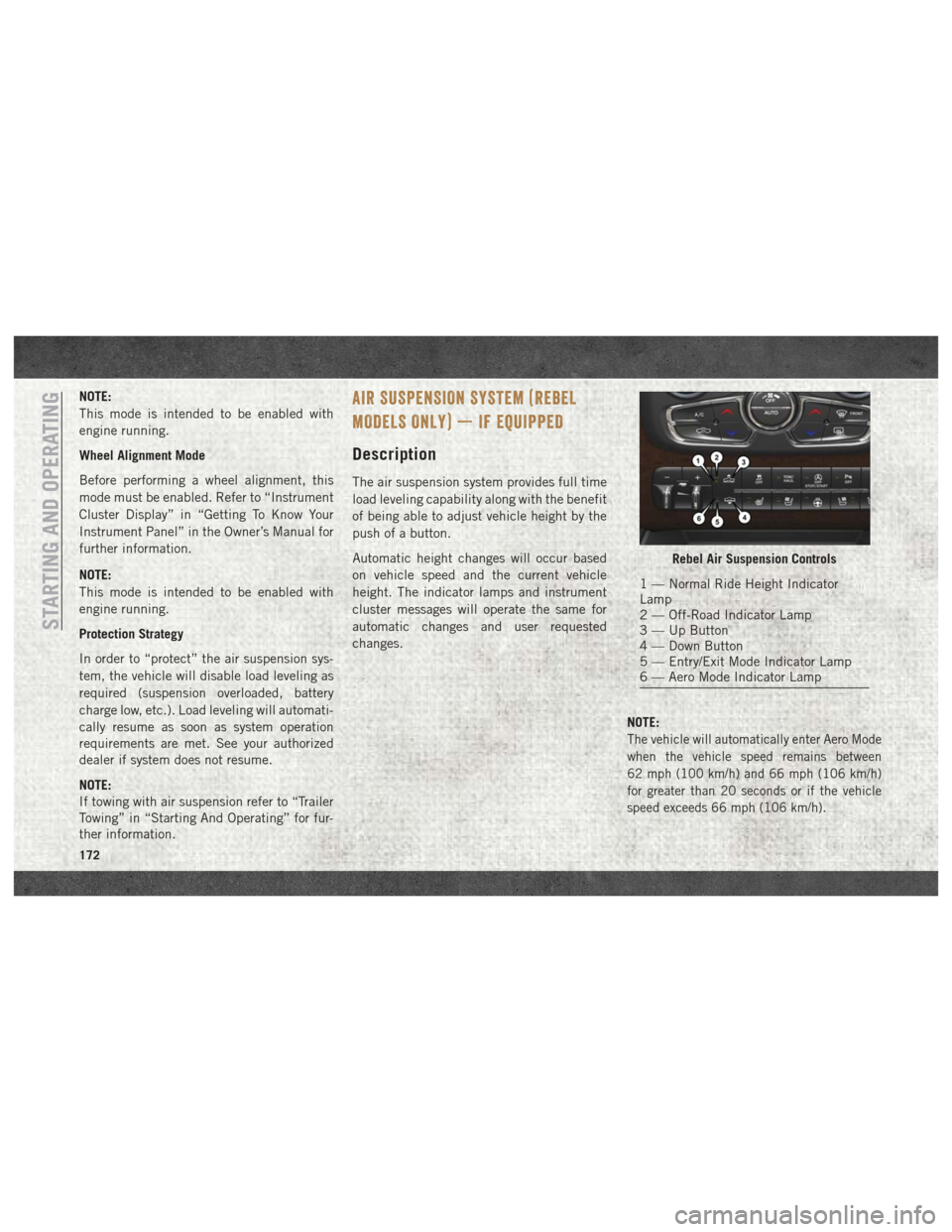
Rebel Air Suspension Controls
1 — Normal Ride Height Indicator
Lamp
2 — Off-Road Indicator Lamp
3 — Up Button
4 — Down Button
5 — Entry/Exit Mode Indicator Lamp
6 — Aero Mode Indicator Lamp
STARTING AND OPERATING
172