torque Ram 2500 2020 Owner's Manual
[x] Cancel search | Manufacturer: RAM, Model Year: 2020, Model line: 2500, Model: Ram 2500 2020Pages: 553, PDF Size: 21.99 MB
Page 11 of 553

9
TECHNICAL SPECIFICATIONS
IDENTIFICATION DATA ...................................... 444Vehicle Identification Number ................. 444
BRAKE SYSTEM ................................................ 444
Hydraulic Brake Assist — If Equipped .......444
WHEEL AND TIRE TORQUE
SPECIFICATIONS ................................................ 444
Torque Specifications ................................444
FUEL REQUIREMENTS — GAS ENGINE ............ 446
6.4L Engine ................................................446
Reformulated Gasoline .............................446
Materials Added To Fuel ...........................446
Gasoline/Oxygenate Blends......................446
Do Not Use E-85 In Non-Flex Fuel
Vehicles ......................................................447 CNG And LP Fuel System Modifications ...447
MMT In Gasoline ........................................447
Fuel System Cautions ................................447
Carbon Monoxide Warnings ......................448
FUEL REQUIREMENTS – DIESEL ENGINE ...... 448
Fuel Specifications ...................................448
Biodiesel Fuel Requirements ....................449
FLUID CAPACITIES — GAS ENGINE .................. 451
FLUID CAPACITIES — DIESEL ENGINE............. 451
FLUIDS AND LUBRICANTS — GAS ENGINE ..... 452
Engine ........................................................ 452
Chassis .......................................................454 FLUIDS AND LUBRICANTS — DIESEL
ENGINE ................................................................ 454
Engine ........................................................ 454
Chassis ....................................................... 457
MULTIMEDIA
UCONNECT SYSTEMS .......................................458
CYBERSECURITY ............................................... 458
UCONNECT SETTINGS ........................................ 459
Uconnect 3 Settings .................................. 459
Uconnect 4/4C/4C NAV Settings ............. 473
Uconnect 4C NAV With 12-inch Display
Settings ...................................................... 493
SAFETY AND GENERAL INFORMATION ........... 511
Safety Guidelines....................................... 511
UCONNECT 3 WITH 5-INCH DISPLAY ..............512
Introduction................................................ 512
Radio Mode ................................................ 513
Media Mode ............................................... 516
Phone Mode ............................................... 518
STEERING WHEEL AUDIO CONTROLS — IF
EQUIPPED ...........................................................525
Radio Operation ......................................... 525
Media Mode ............................................... 525
IPOD®/USB/MP3 CONTROL —
IF EQUIPPED ....................................................... 525 RADIO OPERATION AND MOBILE PHONES.... 527
Regulatory And Safety Information .......... 527
VOICE RECOGNITION QUICK TIPS .................. 529
Introducing Uconnect ................................ 529
Get Started................................................. 529
Basic Voice Commands ............................ 529
Radio .......................................................... 530
Media ......................................................... 530
Phone ......................................................... 531
Voice Text Reply — If Equipped ................. 531
Climate (4C/4C NAV)................................. 532
Navigation (4C NAV) .................................. 532
Siri® Eyes Free — If Equipped ................. 532
Using Do Not Disturb ................................ 532
Android Auto™ — If Equipped .................. 533
Apple CarPlay® — If Equipped ................. 533
General Information .................................. 534
Additional Information............................... 534
CUSTOMER ASSISTANCE
SUGGESTIONS FOR OBTAINING SERVICE FOR
YOUR VEHICLE .................................................. 536
Prepare For The Appointment .................. 536
Prepare A List............................................. 536
Be Reasonable With Requests ................. 536
20_DJD2_OM_EN_USC_t.book Page 9
Page 136 of 553
134GETTING TO KNOW YOUR INSTRUMENT PANEL
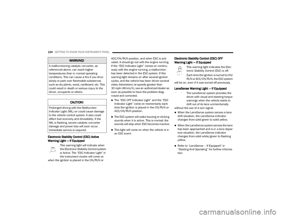
Electronic Stability Control (ESC) Active
Warning Light — If Equipped
This warning light will indicate when
the Electronic Stability Control system
is Active. The “ESC Indicator Light” in
the instrument cluster will come on
when the ignition is placed in the ON/RUN or ACC/ON/RUN position, and when ESC is acti
-
vated. It should go out with the engine running.
If the “ESC Indicator Light” comes on continu -
ously with the engine running, a malfunction
has been detected in the ESC system. If this
warning light remains on after several ignition
cycles, and the vehicle has been driven several
miles (kilometers) at speeds greater than
30 mph (48 km/h), see an authorized dealer as
soon as possible to have the problem diag -
nosed and corrected.
The “ESC OFF Indicator Light” and the “ESC
Indicator Light” come on momentarily each
time the ignition is placed in the ON/RUN or
ACC/ON/RUN position.
The ESC system will make buzzing or clicking
sounds when it is active. This is normal; the
sounds will stop when ESC becomes inactive.
This light will come on when the vehicle is in
an ESC event.
Electronic Stability Control (ESC) OFF
Warning Light — If Equipped
This warning light indicates the Elec -
tronic Stability Control (ESC) is off.
Each time the ignition is turned to ON/
RUN or ACC/ON/RUN, the ESC system
will be on, even if it was turned off previously.
LaneSense Warning Light — If Equipped
The LaneSense system provides the
driver with visual and steering torque
warnings when the vehicle starts to
drift out of its lane unintentionally
without the use of a turn signal.
When the LaneSense system senses a lane
drift situation, the LaneSense indicator
changes from solid green to solid yellow.
When the LaneSense system senses the lane
has been approached and is in a lane depar -
ture situation, the LaneSense indicator
changes from solid white/green to flashing
yellow.
Refer to “LaneSense – If Equipped” in
“Starting And Operating” for further informa -
tion.
WARNING!
A malfunctioning catalytic converter, as
referenced above, can reach higher
temperatures than in normal operating
conditions. This can cause a fire if you drive
slowly or park over flammable substances
such as dry plants, wood, cardboard, etc. This
could result in death or serious injury to the
driver, occupants or others.
CAUTION!
Prolonged driving with the Malfunction
Indicator Light (MIL) on could cause damage
to the vehicle control system. It also could
affect fuel economy and driveability. If the
MIL is flashing, severe catalytic converter
damage and power loss will soon occur.
Immediate service is required.
20_DJD2_OM_EN_USC_t.book Page 134
Page 141 of 553

GETTING TO KNOW YOUR INSTRUMENT PANEL139
4WD Lock Indicator Light
This light alerts the driver that the
vehicle is in the four-wheel drive LOCK
mode. The front and rear driveshafts
are mechanically locked together,
forcing the front and rear wheels to rotate at the
same speed.
Refer to “Four-Wheel Drive Operation” in
“Starting And Operating” for further information
on four-wheel drive operation and proper use.
4WD Low Indicator Light — If Equipped
This light alerts the driver that the
vehicle is in the four-wheel drive LOW
mode. The front and rear driveshafts
are mechanically locked together
forcing the front and rear wheels to rotate at the
same speed. Low range provides a greater gear
reduction ratio to provide increased torque at
the wheels.
Refer to “Four-Wheel Drive Operation — If
Equipped” in “Starting And Operating” for
further information on four-wheel drive opera -
tion and proper use.
4WD High Indicator Light — If Equipped
This light alerts the driver that the
vehicle is in the four-wheel drive HIGH
mode. The front and rear driveshafts
are mechanically locked together
forcing the front and rear wheels to rotate at the
same speed.
NEUTRAL Indicator Light — If Equipped
This light alerts the driver that the
4WD power transfer case is in the
NEUTRAL mode and the front and rear
driveshafts are disengaged from the
powertrain.
Low Diesel Exhaust Fluid (DEF) Indicator
Light — If Equipped
The Low Diesel Exhaust Fluid (DEF)
Indicator will illuminate if the vehicle
is low on Diesel Exhaust Fluid (DEF).
Refer to “Starting And Operating” for
further information.
Wait To Start Light — If Equipped
This indicator light will illuminate for
approximately two seconds when the
ignition is turned to the RUN position.
Its duration may be longer based on colder operating conditions. Vehicle will not
initiate start until telltale is no longer displayed.
Refer to “Starting The Engine” in “Starting And
Operating” for further information.
NOTE:
The “Wait To Start” telltale may not illuminate if
the intake manifold temperature is warm
enough.
Water In Fuel Indicator Light — If Equipped
The “Water In Fuel Indicator Light” will
illuminate when there is water
detected in the fuel filter. If this light
remains on, DO NOT start the vehicle
before you drain the water from the fuel filter to
prevent engine damage.
Refer to the “Draining Fuel/Water Separator
Filter” section in “Dealer Service” in “Servicing
And Maintenance” for further information.
3
20_DJD2_OM_EN_USC_t.book Page 139
Page 142 of 553
140GETTING TO KNOW YOUR INSTRUMENT PANEL
Green Indicator Lights
Adaptive Cruise Control (ACC) Set With Target
Light — If Equipped
This will display when the ACC is set
and a target vehicle is detected.
Refer to “Adaptive Cruise Control
(ACC) — If Equipped” in “Starting And
Operating” for further information.
Adaptive Cruise Control (ACC) Set With No
Target Detected Indicator Light — If Equipped
This light will turn on when the Adap -
tive Cruise Control is SET and there is
no target vehicle detected.
Refer to "Adaptive Cruise Control (ACC) — If
Equipped" in "Starting And Operating" for
further information.
Automatic Diesel Exhaust Brake Indicator
Light — If Equipped
This indicator light will illuminate
when the Diesel Exhaust Brake has
been activated, and has switched to
Automatic mode.
Refer to “Diesel Exhaust Brake — Engine
Braking (If Equippes)” in “Starting And Oper -
ating” for further information.
ECO Mode Indicator Light
This light will turn on when ECO Mode
is active.
Park/Headlight On Indicator Light
This indicator light will illuminate
when the park lights or headlights are
turned on.
Refer to “Exterior Lights” in “Getting To Know
Your Vehicle” for further information.
LaneSense Indicator Light — If Equipped
The LaneSense indicator light illumi -
nates solid green when both lane
markings have been detected and the
system is “armed” and ready to
provide visual and torque warnings if an unin -
tentional lane departure occurs.
Refer to “LaneSense — If Equipped” in “Starting
And Operating” for further information.
Front Fog Indicator Light — If Equipped
This indicator light will illuminate
when the front fog lights are on.
Refer to “Exterior Lights” in “Getting
To Know Your Vehicle” for further
information.
Turn Signal Indicator Lights
When the left or right turn signal is
activated, the turn signal indicator will
flash independently and the corre -
sponding exterior turn signal lamps
will flash. Turn signals can be activated when
the multifunction lever is moved down (left) or
up (right).
NOTE:
A continuous chime will sound if the vehicle is
driven more than 1 mile (1.6 km) with either
turn signal on.
Check for an inoperative outside light bulb if
either indicator flashes at a rapid rate.
If equipped with fog lamps, the fog lamp on
the side of the activated turn signal will also
illuminate to provide additional light when
turning.
20_DJD2_OM_EN_USC_t.book Page 140
Page 148 of 553
146SAFETY
(Continued)
Electronic Brake Force Distribution (EBD)
This function manages the distribution of the
braking torque between the front and rear axles
by limiting braking pressure to the rear axle.
This is done to prevent overslip of the rear
wheels to avoid vehicle instability, and to
prevent the rear axle from entering Anti-Lock
Brake System (ABS) before the front axle.
Electronic Stability Control (ESC)
This system enhances directional control and
stability of the vehicle under various driving
conditions. Electronic Stability Control (ESC)
corrects for oversteering or understeering of the
vehicle by applying the brake of the appropriate
wheel(s) to assist in counteracting the oversteer
or understeer condition. Engine power may also
be reduced to help the vehicle maintain the
desired path.
ESC uses sensors in the vehicle to determine
the vehicle path intended by the driver and
compares it to the actual path of the vehicle.
When the actual path does not match the
intended path, ESC applies the brake of the
appropriate wheel to assist in counteracting the
oversteer or understeer condition.
Oversteer — when the vehicle is turning more
than appropriate for the steering wheel posi-
tion.
Understeer — when the vehicle is turning less
than appropriate for the steering wheel posi -
tion.
The “ESC Activation/Malfunction Indicator
Light” located in the instrument cluster will start
to flash as soon as the ESC system becomes
active. The “ESC Activation/Malfunction Indi -
cator Light” also flashes when the TCS is active.
If the “ESC Activation/Malfunction Indicator
Light” begins to flash during acceleration, ease
up on the accelerator and apply as little throttle
as possible. Be sure to adapt your speed and
driving to the prevailing road conditions.
WARNING!
Electronic Stability Control (ESC) cannot
prevent the natural laws of physics from
acting on the vehicle, nor can it increase
the traction afforded by prevailing road
conditions. ESC cannot prevent accidents,
including those resulting from excessive
speed in turns, driving on very slippery
surfaces, or hydroplaning. ESC also cannot
prevent accidents resulting from loss of
vehicle control due to inappropriate driver
input for the conditions. Only a safe, atten -
tive, and skillful driver can prevent acci -
dents. The capabilities of an ESC equipped
vehicle must never be exploited in a reck -
less or dangerous manner which could
jeopardize the user’s safety or the safety of
others.
20_DJD2_OM_EN_USC_t.book Page 146
Page 150 of 553
148SAFETY
(Continued)
NOTE:
System may switch from ESC “Full Off” to
“Partial Off” mode when vehicle exceeds a
predetermined speed. When the vehicle speed
slows below the predetermined speed the
system will return to ESC “Full Off”.
ESC modes may also be affected by drive
modes (if equipped).
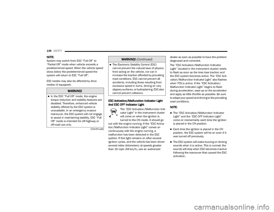
ESC Activation/Malfunction Indicator Light
And ESC OFF Indicator Light
The “ESC Activation/Malfunction Indi -
cator Light” in the instrument cluster
will come on when the ignition is
turned to the ON mode. It should go
out with the engine running. If the “ESC Activa -
tion/Malfunction Indicator Light” comes on
continuously with the engine running, a
malfunction has been detected in the ESC
system. If this light remains on after several
ignition cycles, and the vehicle has been driven
several miles (kilometers) at speeds greater
than 30 mph (48 km/h), see an authorized dealer as soon as possible to have the problem
diagnosed and corrected.
The “ESC Activation/Malfunction Indicator
Light” (located in the instrument cluster) starts
to flash as soon as the tires lose traction and
the ESC system becomes active. The “ESC Acti
-
vation/Malfunction Indicator Light” also flashes
when TCS is active. If the “ESC Activation/
Malfunction Indicator Light” begins to flash
during acceleration, ease up on the accelerator
and apply as little throttle as possible. Be sure
to adapt your speed and driving to the prevailing
road conditions.
NOTE:
The “ESC Activation/Malfunction Indicator
Light” and the “ESC OFF Indicator Light”
come on momentarily each time the ignition
is placed in the ON position.
Each time the ignition is placed in the ON
position, the ESC system will be on even if it
was turned off previously.
The ESC system will make buzzing or clicking
sounds when it is active. This is normal; the
sounds will stop when ESC becomes inactive
following the maneuver that caused the ESC
activation.
WARNING!
In the ESC “Full Off” mode, the engine
torque reduction and stability features are
disabled. Therefore, enhanced vehicle
stability offered by the ESC system is
unavailable. In an emergency evasive
maneuver, the ESC system will not engage
to assist in maintaining stability. ESC “Full
Off” mode is intended for off-highway or
off-road use only.
The Electronic Stability Control (ESC)
cannot prevent the natural laws of physics
from acting on the vehicle, nor can it
increase the traction afforded by prevailing
road conditions. ESC cannot prevent all
accidents, including those resulting from
excessive speed in turns, driving on very
slippery surfaces, or hydroplaning. ESC also
cannot prevent collisions.
WARNING! (Continued)
20_DJD2_OM_EN_USC_t.book Page 148
Page 232 of 553
230STARTING AND OPERATING
DIESEL EXHAUST BRAKE — ENGINE
BRAKING (IF EQUIPPED)
The purpose of the exhaust brake (engine
braking) feature is to supply negative (braking)
torque from the engine. Typically, the engine
braking is used for, but not limited to, vehicle
towing applications where vehicle braking can be achieved by the internal engine power,
thereby sparing the mechanical brakes of the
vehicle.
Benefits of the exhaust brake are:
Vehicle driving control.
Reduced brake fade.
Longer brake life.
Faster cab warm-up.
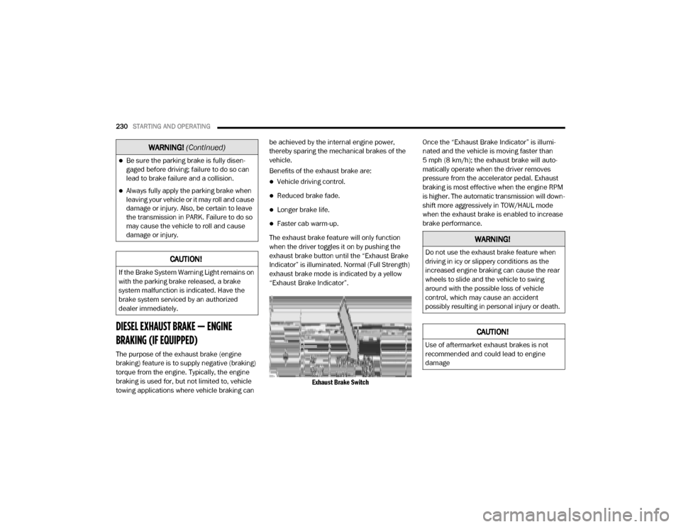
The exhaust brake feature will only function
when the driver toggles it on by pushing the
exhaust brake button until the “Exhaust Brake
Indicator” is illuminated. Normal (Full Strength)
exhaust brake mode is indicated by a yellow
“Exhaust Brake Indicator”.
Exhaust Brake Switch
Once the “Exhaust Brake Indicator” is illumi
-
nated and the vehicle is moving faster than
5 mph (8 km/h); the exhaust brake will auto -
matically operate when the driver removes
pressure from the accelerator pedal. Exhaust
braking is most effective when the engine RPM
is higher. The automatic transmission will down -
shift more aggressively in TOW/HAUL mode
when the exhaust brake is enabled to increase
brake performance.
Be sure the parking brake is fully disen -
gaged before driving; failure to do so can
lead to brake failure and a collision.
Always fully apply the parking brake when
leaving your vehicle or it may roll and cause
damage or injury. Also, be certain to leave
the transmission in PARK. Failure to do so
may cause the vehicle to roll and cause
damage or injury.
CAUTION!
If the Brake System Warning Light remains on
with the parking brake released, a brake
system malfunction is indicated. Have the
brake system serviced by an authorized
dealer immediately.
WARNING! (Continued)
WARNING!
Do not use the exhaust brake feature when
driving in icy or slippery conditions as the
increased engine braking can cause the rear
wheels to slide and the vehicle to swing
around with the possible loss of vehicle
control, which may cause an accident
possibly resulting in personal injury or death.
CAUTION!
Use of aftermarket exhaust brakes is not
recommended and could lead to engine
damage
20_DJD2_OM_EN_USC_t.book Page 230
Page 242 of 553
240STARTING AND OPERATING
engine may be started in this range. Apply the
parking brake and shift the transmission into
PARK if you must exit the vehicle.
DRIVE (D)
This range should be used for most city and
highway driving. It provides the smoothest
upshifts and downshifts, and the best fuel
economy. The transmission automatically
upshifts through underdrive first, second, and third gears, direct fourth gear and overdrive fifth
and sixth gears. The DRIVE position provides
optimum driving characteristics under all
normal operating conditions.
When frequent transmission shifting occurs
(such as when operating the vehicle under
heavy loading conditions, in hilly terrain, trav
-
eling into strong head winds, or while towing a
heavy trailer), use the Electronic Range Select
(ERS) shift control refer to “Electronic Range
Select (ERS) Operation” in this section for
further information to select a lower gear range.
Under these conditions, using a lower gear
range will improve performance and extend
transmission life by reducing excessive shifting
and heat buildup.
If the transmission temperature exceeds
normal operating limits, the powertrain
controller will modify the transmission shift
schedule and expand the range of torque
converter clutch engagement. This is done to
prevent transmission damage due to over -
heating.
If the transmission becomes extremely hot or is
in danger of overheating, the “Transmission
Temperature Warning Light” may illuminate and
the transmission may operate differently until
the transmission cools down. NOTE:
Use caution when operating a heavily loaded
vehicle at low speeds (such as towing a trailer
up a steep grade, or in stop-and-go traffic)
during hot weather. In these conditions, torque
converter slip can impose a significant addi
-
tional heat load on the cooling system. Down -
shifting the transmission to the lowest possible
gear (when climbing a grade), or shifting to
NEUTRAL (when stopped in heavy traffic) can
help to reduce this excess heat generation.
During cold temperatures, transmission opera -
tion may be modified depending on engine and
transmission temperature as well as vehicle
speed. This feature improves warm up time of
the engine and transmission to achieve
maximum efficiency. Engagement of the torque
converter clutch is inhibited until the transmis -
sion fluid is warm refer to the “Note” under
“Torque Converter Clutch” in this section. On
Pickup models with 68RFE transmission, top
overdrive gear is also inhibited until the trans -
mission fluid is warm, and during extremely cold
temperatures (-16°F [-27°C] or below), opera -
tion may briefly be limited to first and direct
gears only. On trucks with AS69RC transmis -
sion, fifth and sixth gears may be inhibited
briefly on cold starts below 41°F (5°C), and
WARNING!
Do not coast in NEUTRAL and never turn off
the ignition to coast down a hill. These are
unsafe practices that limit your response to
changing traffic or road conditions. You might
lose control of the vehicle and have a
collision.
CAUTION!
Towing the vehicle, coasting, or driving for any
other reason with the transmission in
NEUTRAL can cause severe transmission
damage. Refer to “Recreational Towing” in
“Starting And Operating” and “Towing A
Disabled Vehicle” in “In Case Of Emergency”
for further information.
20_DJD2_OM_EN_USC_t.book Page 240
Page 245 of 553
STARTING AND OPERATING243
Torque Converter Clutch
A feature designed to improve fuel economy
has been included in the automatic transmis -
sion on your vehicle. A clutch within the torque
converter engages automatically at calibrated
speeds. This may result in a slightly different
feeling or response during normal operation in
the upper gears. When the vehicle speed drops
or during some accelerations, the clutch auto -
matically disengages.
NOTE:
The torque converter clutch will not engage,
until the transmission fluid and engine
coolant are warm [usually after 1 to 3 miles
(2 to 5 km) of driving]. Because engine speed
is higher when the torque converter clutch is
not engaged, it may seem as if the transmis -
sion is not shifting properly when cold. This is normal. Using the Electronic Range Select
(ERS) shift control, when the transmission is
sufficiently warm, will demonstrate that the
transmission is able to shift into and out of
Overdrive.
If the vehicle has not been driven for several
days, the first few seconds of operation after
shifting the transmission into gear may seem
sluggish. This is due to the fluid partially
draining from the torque converter into the
transmission. This condition is normal and
will not cause damage to the transmission.
The torque converter will refill within five
seconds after starting the engine.
AUXILIARY SWITCHES — IF EQUIPPED
There can be up to six auxiliary switches located
in the lower switch bank of the instrument panel
which can be used to power various electronic
devices and PTO (Power Take Off) – If Equipped.
If Power Take Off is equipped, it will take the
place of the sixth Auxiliary switch. Connections
to the switches are found under the hood in the
connectors attached to the auxiliary Power
Distribution Center.
You have the ability to configure the function
-
ality of the auxiliary switches via the instrument cluster display. All switches can now be config
-
ured for setting the switch type operation to
latching or momentary, power source of either
battery or ignition, and ability to hold last state
across key cycles.
NOTE:
Holding last state conditions are met when
switch type is set to latching and power source
is set to ignition.
For further information on using the auxiliary
switches, please refer to the Ram Body Builders
Guide by accessing www.rambodybuilder.com
and choosing the appropriate links.
ACTIVE NOISE CANCELLATION
Your vehicle is equipped with an Active Noise
Cancellation system that cannot be turned off.
This system is designed to address exhaust and
engine noise. The system relies on four micro -
phones embedded in the headliner, which
monitor exhaust and engine noise, and assists
an onboard frequency generator, which creates
counteracting sound waves in the audio
system’s speakers. This helps keep the vehicle
quiet at idle and during drive. The system is
deactivated when the windows are rolled down.
WARNING!
Do not use the “TOW/HAUL” feature when
driving in icy or slippery conditions. The
increased engine braking can cause the rear
wheels to slide, and the vehicle to swing
around with the possible loss of vehicle
control, which may cause an accident
possibly resulting in personal injury or death.
5
20_DJD2_OM_EN_USC_t.book Page 243
Page 246 of 553

244STARTING AND OPERATING
(Continued)
FOUR-WHEEL DRIVE OPERATION — IF
EQUIPPED
Four-wheel drive trucks are equipped with
either a manually shifted transfer case or an
electronically shifted transfer case. Refer to the
operating instructions for your transfer case,
located in this section for further information.
Four-Position Electronically Shifted Transfer
Case — If Equipped
This is an electronic shift transfer case and is
operated by the 4WD Control Switch (Transfer
Case Switch), which is located on the instru-
ment panel.
Four-Position Transfer Case
This electronically shifted transfer case
provides four mode positions:
Two-Wheel Drive High Range (2WD)
Four-Wheel Drive High Range (4WD HIGH)
Four-Wheel Drive Low Range (4WD LOW)
N (Neutral)
For additional information on the appropriate
use of each transfer case mode position, see
the information below:
2WD
Two-Wheel Drive High Range — This range is for
normal street and highway driving on dry hard
surfaced roads.
4WD HIGH
Four-Wheel Drive High Range — This range
provides torque to the front driveshaft (engages
four-wheel drive) which allows front and rear
wheels to spin at the same speed. This provides
additional traction for loose, slippery road
surfaces only.
4WD LOW
Four-Wheel Drive Low Range — This range
provides low speed four-wheel drive. It maxi -
mizes torque (increased torque over 4WD HIGH)
to the front driveshaft, allowing front and rear wheels to rotate at the same speed. This range
provides additional traction and maximum
pulling power for loose, slippery road surfaces
only. Do not exceed 25 mph (40 km/h) in this
range.
N (Neutral)
N (Neutral) — This range disengages both the
front and rear driveshafts from the powertrain.
To be used for flat towing behind another
vehicle. Refer to “Recreational Towing” in this
section for further information.
WARNING!
You or others could be injured or killed if
you leave the vehicle unattended with the
transfer case in the NEUTRAL (N) position
without first fully engaging the parking
brake. The transfer case NEUTRAL (N) posi -
tion disengages both the front and rear
drive shaft from the powertrain, and will
allow the vehicle to roll, even if the trans -
mission is in PARK. The parking brake
should always be applied when the driver is
not in the vehicle.
20_DJD2_OM_EN_USC_t.book Page 244