tow Ram 2500 2020 Owners Manual
[x] Cancel search | Manufacturer: RAM, Model Year: 2020, Model line: 2500, Model: Ram 2500 2020Pages: 553, PDF Size: 21.99 MB
Page 333 of 553

STARTING AND OPERATING331
RECREATIONAL TOWING (BEHIND MOTORHOME, ETC.)
Towing This Vehicle Behind Another Vehicle
NOTE:
When towing your vehicle, always follow
applicable state and provincial laws. Contact
state and provincial Highway Safety offices
for additional details.
Vehicles equipped with air suspension must
be placed in Transport mode before tying
them down (from the body) on a trailer or
flatbed truck. Refer to “Air Suspension – If
Equipped” for more information. If the
vehicle cannot be placed in Transport mode (for example, engine will not run), tie-downs
must be fastened to the axles (not to the
body). Failure to follow these instructions
may cause fault codes to be set and/or
cause loss of proper tie-down tension.Recreational Towing — Two-Wheel Drive
Models
DO NOT flat tow this vehicle. Damage to the
drivetrain will result.
Recreational towing (for two-wheel drive
models) is allowed
ONLY if the rear wheels are OFF
the ground. This may be accomplished
using a tow dolly or vehicle trailer. If using a tow
dolly, follow this procedure:
NOTE:
If vehicle is equipped with air suspension,
ensure the vehicle is set to Normal Ride Height.
1. Properly secure the dolly to the tow vehicle, following the dolly manufacturer's instruc -
tions.
2. Drive the rear wheels onto the tow dolly.
Towing Condition Wheels OFF The
Ground Two-Wheel Drive
Models Four-Wheel Drive Models
Flat Tow
NONENOT ALLOWED See Instructions
Automatic transmission in PARK
Transfer case in NEUTRAL (N)
Tow in forward direction
Dolly Tow Front
NOT ALLOWED NOT ALLOWED
Rear OK NOT ALLOWED
On Trailer ALLOK OK
5
20_DJD2_OM_EN_USC_t.book Page 331
Page 334 of 553
332STARTING AND OPERATING
(Continued)
3. Firmly apply the parking brake. Place auto-
matic transmission in PARK.
4. Properly secure the rear wheels to the dolly, following the dolly manufacturer's instruc -
tions.
5. Turn the ignition OFF and remove the key fob.
6. Install a suitable clamping device, designed for towing, to secure the front wheels in the
straight position.Recreational Towing — Four-Wheel Drive
Models
NOTE:
Both the manual shift and electronic shift
transfer cases must be shifted into NEUTRAL
(N) for recreational towing. Automatic transmis -
sions must be shifted into PARK for recreational
towing. Refer to the following for the proper
transfer case NEUTRAL (N) shifting procedure
for your vehicle.
CAUTION!
Towing with the rear wheels on the ground
will cause severe transmission damage.
Damage from improper towing is not
covered under the New Vehicle Limited
Warranty.
Do not disconnect the driveshaft because
fluid may leak from the transmission,
causing damage to internal parts.
CAUTION!
DO NOT dolly tow any 4WD vehicle. Towing
with only one set of wheels on the ground
(front or rear) will cause severe transmis -
sion and/or transfer case damage. Tow
with all four wheels either ON the ground, or
OFF the ground (using a vehicle trailer).
Tow only in the forward direction. Towing
this vehicle backwards can cause severe
damage to the transfer case.
Before recreational towing, the transfer
case must be in NEUTRAL. To be certain the
transfer case is fully in NEUTRAL, perform
the procedure outlined under “Shifting Into
NEUTRAL”. Internal transmission damage
will result, if the transfer case is not in
NEUTRAL during towing.
The transmission must be placed in PARK
for recreational towing.
Towing this vehicle in violation of the above
requirements can cause severe transmis -
sion and/or transfer case damage.
Damage from improper towing is not
covered under the New Vehicle Limited
Warranty.
Do not disconnect the rear driveshaft
because fluid will leak from the transfer
case, causing damage to internal parts.
Do not use a bumper-mounted clamp-on
tow bar on your vehicle. The bumper face
bar will be damaged.
CAUTION! (Continued)
20_DJD2_OM_EN_USC_t.book Page 332
Page 335 of 553
STARTING AND OPERATING333
Shifting Into (N) NEUTRAL
Use the following procedure to prepare your
vehicle for recreational towing.
1. Bring the vehicle to a complete stop on
level ground, with the engine running.
Firmly apply the parking brake.
2. Shift the transmission to NEUTRAL. NOTE:
If vehicle is equipped with air suspension,
ensure the vehicle is set to Normal Ride Height.
3. Press and hold the brake pedal.
4. Shift the transfer case into N (Neutral):
With manual shift transfer case, shift the
transfer case lever into N (Neutral)
With electronic shift transfer case, push and hold the transfer case N (Neutral)
button. Some models have a small,
recessed “N” button (at the center of the
transfer case switches) that must be
pushed using a ballpoint pen or similar
object. Other models have a rectangular
N (Neutral) switch, below the rotary
transfer case control knob. The N
(Neutral) indicator light will blink while
the shift is in progress. The light will stop
blinking (stay on solid) when the shift to N
(Neutral) is complete. After the shift is
completed and the N (Neutral) light stays
on, release the N (Neutral) button.
5. Release the parking brake.
6. Shift the transmission into REVERSE. 7. Release the brake pedal for five seconds
and ensure that there is no vehicle move-
ment.
8. Repeat steps 6 and 7 with automatic trans -
mission in DRIVE.
9. Shift the transmission to NEUTRAL. Firmly apply the parking brake. Turn off the engine.
For vehicles with Keyless Enter-N-Go, push
and hold the ENGINE START/STOP button
until the engine shuts off.
10. Shift the transmission into PARK. On 8-speed transmissions the shifter will auto -
matically select PARK when the engine is
turned off.
11. Turn the ignition to the OFF mode, then cycle the ignition to the RUN mode and back
to the OFF mode. Remove the key fob from
the ignition.
12. Attach the vehicle to the tow vehicle using a suitable tow bar.
13. Release the parking brake.
WARNING!
You or others could be injured or killed if you
leave the vehicle unattended with the transfer
case in the NEUTRAL (N) position without first
fully engaging the parking brake. The transfer
case NEUTRAL (N) position disengages both
the front and rear driveshafts from the
powertrain, and will allow the vehicle to roll,
even if the automatic transmission is in PARK.
The parking brake should always be applied
when the driver is not in the vehicle.
CAUTION!
It is necessary to follow these steps to be
certain that the transfer case is fully in
NEUTRAL (N) before recreational towing to
prevent damage to internal parts.
5
20_DJD2_OM_EN_USC_t.book Page 333
Page 336 of 553
334STARTING AND OPERATING
NOTE:
With electronic shift transfer case:
Steps 2 through 3 are requirements that
must be met before pushing the N (Neutral)
button, and must continue to be met until the
shift has been completed. If any of these
requirements are not met before pushing the
N (Neutral) button or are no longer met
during the shift, the N (Neutral) indicator light
will flash continuously until all requirements
are met or until the N (Neutral) button is
released.
The ignition must be in the ON/RUN mode for
a shift to take place and for the position indi -
cator lights to be operable. If the ignition is
not in the ON/RUN mode, the shift will not
take place and no position indicator lights will
be on or flashing.
A flashing N (Neutral) position indicator light
indicates that shift requirements have not
been met.
If the vehicle is equipped with air suspension,
the engine should be started and left running
for a minimum of 60 seconds (with all the
doors closed) at least once every 24 hours. This process allows the air suspension to
adjust the vehicle’s ride height to compen
-
sate for temperature effects.
Shifting Out Of (N) NEUTRAL
Use the following procedure to prepare your
vehicle for normal usage:
1. Bring the vehicle to a complete stop,
leaving it connected to the tow vehicle.
2. Firmly apply the parking brake.
3. Press and hold the brake pedal.
4. Start the engine. Shift the transmission into NEUTRAL.
With manual shift transfer case, shift the transfer case lever to the desired posi -
tion.
With electronic shift transfer case with rotary selector switch, push and hold the
transfer case N (Neutral) button until the
N (Neutral) indicator light turns off. After
the N (Neutral) indicator light turns off,
release the N (Neutral) button. After the
N (Neutral) button has been released, the
transfer case will shift to the position indi -
cated by the selector switch.
With electronic shift transfer case with push-button selector switch, push and
hold the switch for the desired transfer
case position, until the N (Neutral) indi -
cator light turns off and the desired posi -
tion indicator light turns on.
NOTE:
When shifting out of transfer case N (Neutral),
turning the engine OFF is not required, but may
be helpful to avoid gear clash. With the 8-speed
automatic transmission, the engine must
remain running, since turning the engine OFF
will shift the transmission to PARK (and the
transmission must be in NEUTRAL for the
transfer case to shift out of NEUTRAL).
5. Turn the engine off. Shift automatic trans -
mission into PARK. On 8-speed transmis -
sions the shifter will automatically select
PARK when the engine is turned off.
6. Release the brake pedal.
7. Disconnect vehicle from the tow vehicle.
8. Start the engine.
9. Press and hold the brake pedal.
20_DJD2_OM_EN_USC_t.book Page 334
Page 341 of 553
IN CASE OF EMERGENCY339
NOTE:
Your vehicle may be transmitting data as
authorized by the subscriber.
The SOS and ASSIST buttons will only func -
tion if you are connected to an operable LTE
(voice/data) or 4G (data) network. Other
Uconnect services will only be operable if
your SiriusXM Guardian™ service is active
and you are connected to an operable LTE
(voice/data) or 4G (data) network. ASSIST Call
The ASSIST Button is used to automatically
connect you to any one of the following support
centers:
Roadside Assistance – If you get a flat tire, or
need a tow, just push the ASSIST button and
you’ll be connected to someone who can
help. Roadside Assistance will know what
vehicle you’re driving and its location. Addi
-
tional fees may apply for roadside assis -
tance.
SiriusXM Guardian™ Customer Care –
In-vehicle support for SiriusXM Guardian™.
Vehicle Customer Care – Total support for all
other vehicle issues.
SOS Call
1. Push the SOS Call button on the overhead console.
NOTE:
In case the SOS Call button is pushed in error,
there will be a 10 second delay before the SOS
Call system initiates a call to a SOS operator. To
cancel the SOS Call connection, push the SOS
call button on the overhead console or press the cancellation button on the Device Screen.
Termination of the SOS Call will turn off the
green LED light on the overhead console.
2. The LED light located between the ASSIST
and SOS buttons on the overhead console
will turn green once a connection to a SOS
operator has been made.
3. Once a connection between the vehicle and a SOS operator is made, the SOS Call
system may transmit the following
important vehicle information to a SOS
operator: Indication that the occupant placed a SOS Call.
The vehicle brand.
The last known GPS coordinates of the vehicle.
4. You should be able to speak with the SOS operator through the vehicle audio system
to determine if additional help is needed.
WARNING!
ALWAYS obey traffic laws and pay attention to
the road. ALWAYS drive safely with your hands
on the steering wheel. You have full
responsibility and assume all risks related to
the use of the features and applications in
this vehicle. Only use the features and
applications when it is safe to do so. Failure
to do so may result in an accident involving
serious injury or death.
6
20_DJD2_OM_EN_USC_t.book Page 339
Page 345 of 553
IN CASE OF EMERGENCY343
NOTE:
If your vehicle is equipped with an air suspen -
sion system, there is a feature which allows the
automatic leveling to be disabled to assist with
changing a tire.
This feature can be activated through the Ucon -
nect system.
Refer to “Uconnect Settings” in “Multimedia”
for further information.
Jack Location
The jack and jack tools are stored under the
front passenger seat.
Removal Of Jack And Tools
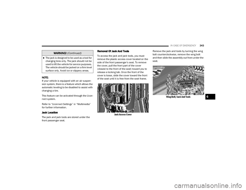
To access the jack and jack tools, you must
remove the plastic access cover located on the
side of the front passenger’s seat. To remove
the cover, pull the front part of the cover
(closest to the front of the seat) toward you to
release a locking tab. Once the front of the
cover is loose, slide the cover toward the front
of the seat until it is free from the seat frame.
Jack Access Cover
Remove the jack and tools by turning the wing
bolt counterclockwise, remove the wing bolt
and then slide the assembly out from under the
seat.
Wing Bolt/Jack And Tools
The jack is designed to be used as a tool for
changing tires only. The jack should not be
used to lift the vehicle for service purposes.
The vehicle should be jacked on a firm level
surface only. Avoid ice or slippery areas.
WARNING! (Continued)
6
20_DJD2_OM_EN_USC_t.book Page 343
Page 349 of 553
IN CASE OF EMERGENCY347
(Continued)
Jacking Instructions
Jack Warning Label Lug Wrench Adapter Shown In Jack And Tools Assembly
1. Remove the spare wheel, jack, and tools
from storage.
2. Using the lug wrench, loosen, but do not remove, the wheel nuts by turning them
counterclockwise one turn while the wheel
is still on the ground. Changing a dually tire
requires the lug wrench adapter.
WARNING!
Carefully follow these tire changing warnings
to help prevent personal injury or damage to
your vehicle:
Always park on a firm, level surface as far
from the edge of the roadway as possible
before raising the vehicle.
Turn on the Hazard Warning Flashers.
Apply the parking brake firmly and set the
transmission in PARK.
Block the wheel diagonally opposite the
wheel to be raised.
Never start or run the engine with the
vehicle on a jack.
Do not let anyone sit in the vehicle when it
is on a jack.
Do not get under the vehicle when it is on a
jack. If you need to get under a raised
vehicle, take it to a service center where it
can be raised on a lift.
Only use the jack in the positions indicated
and for lifting this vehicle during a tire
change.
If working on or near a roadway, be
extremely careful of motor traffic.
To assure that spare tires, flat or inflated,
are securely stowed, spares must be
stowed with the valve stem facing the
ground.
WARNING! (Continued)
CAUTION!
Do not attempt to raise the vehicle by jacking
on locations other than those indicated in the
Jacking Instructions for this vehicle.
6
20_DJD2_OM_EN_USC_t.book Page 347
Page 351 of 553

IN CASE OF EMERGENCY349
under the axle between the spring and the
shock absorber with the extension tubes ex -
tending to the rear.
Rear Lifting Point
Rear Jacking Location
Connect the extension tubes and lug
wrench. NOTE:
If the bottle jack will not lower by turning the dial
(thumbwheel) by hand, it may be necessary to
use the jack driver in order to lower the jack.
4. By rotating the lug wrench clockwise, raise
the vehicle until the wheel just clears the
surface.
5. Remove the lug nuts and pull the wheel off. On Single Rear Wheel (SRW) trucks, install
the spare wheel and lug nuts with the cone
shaped end of the wheel nuts toward the
wheel. On 3500 Dual Rear Wheel models
(DRW) trucks, if the outer tire is being replaced then leave the inner wheel on the
vehicle. If the inner wheel is being replaced
remove the outer wheel and replace the
inner wheel. The wheel nuts are a two-piece
assembly with a flat face. Lightly tighten the
lug nuts. To avoid the risk of forcing the
vehicle off the jack, do not fully tighten the
lug nuts until the vehicle has been lowered.
Rear Inner Wheel Proper Placement (Dual Rear Wheel Equipped)
CAUTION!
Before raising the wheel off the ground, make
sure that the jack will not damage
surrounding truck parts and adjust the jack
position as required.
WARNING!
Raising the vehicle higher than necessary can
make the vehicle less stable. It could slip off
the jack and hurt someone near it. Raise the
vehicle only enough to remove the tire.
6
20_DJD2_OM_EN_USC_t.book Page 349
Page 352 of 553

350IN CASE OF EMERGENCY
Dual Rear Wheel Jack Placement
6. Finish tightening the lug nuts. Push down on the lug wrench while at the end of the handle
for increased leverage. Tighten the lug nuts in
a star pattern until each nut has been tight -
ened twice. For the correct lug nut torque refer
to “Wheel And Tire Torque Specifications” in
“Technical Specifications”. If in doubt about
the correct tightness, have them checked with
a torque wrench by an authorized dealer or
service station. 7. Install the wheel center cap and remove the
wheel blocks. Do not install chrome or
aluminum wheel center caps on the spare
wheel. This may result in cap damage.
8. Lower the jack to its fully closed position. Stow the replaced tire, jack, and tools as
previously described.
NOTE:
The bottle jack will not lower by turning the dial
(thumbwheel) by hand, it may be necessary to
use the jack driver in order to lower the jack.
9. Adjust the tire pressure when possible.
NOTE:
Do not oil wheel studs. For chrome wheels, do
not substitute with chrome plated lug nuts.
To Stow The Flat Or Spare
NOTE:
Have the flat tire repaired or replaced immedi -
ately.
1. Turn the wheel so that the valve stem is facing the ground and toward the rear of
the vehicle for convenience in checking the
spare tire inflation. Slide the wheel retainer
through the center of the wheel.
Reinstalling The Retainer
WARNING!
A loose tire or jack thrown forward in a
collision or hard stop, could endanger the
occupants of the vehicle. Always stow the jack
parts and the spare tire in the places
provided.
WARNING!
A loose tire or jack thrown forward in a
collision or hard stop could endanger the
occupants of the vehicle. Always stow the jack
parts and the spare tire in the places
provided. Have the deflated (flat) tire repaired
or replaced immediately.
20_DJD2_OM_EN_USC_t.book Page 350
Page 357 of 553
IN CASE OF EMERGENCY355
F0940 Amp Green (SSV &
Cummins Diesel) –
Aux Relay Output / Diesel Fuel Heater – If Equipped
F09 30 Amp Pink –Brake Vacuum Pump – If Equipped (HD Only)
F10 40 Amp Green –Body Controller / Exterior Lighting #2
F11 30 Amp Pink –PWR - Trailer Tow Electric Brake Batt Feed – If Equipped
(DS 1500 Only)
F11 40 Amp Green –Brake System Module (ECU and Valves) (HD Only)
F12 40 Amp Green –Body Controller #3
F13 40 Amp Green –Blower Motor
F14 40 Amp Green –Body Controller #4 / Exterior Lighting
F15 30 Amp Pink
40 Amp Green –
–Power Side Steps – If Equipped (HD Only)
Extra Fuse - SSV Only
F16 30 Amp Pink –Smart-Bar Module – If Equipped (HD Only)
F17 30 Amp Pink –Winch Control Module – If Equipped (HD Only)
F19 20 Amp Blue (DS 1500 LD
Diesel)
30 Amp Pink (Cummins Diesel) –
SCR – If Equipped
F20 30 Amp Pink –Passenger Door Module
F21 30 Amp Pink –Drive Train Control Module
F22 20 Amp Blue –Engine Control Module GPEC / Heavy Duty / Other – If
Equipped
Cavity
Cartridge Fuse Micro Fuse Description
6
20_DJD2_OM_EN_USC_t.book Page 355