tailgate Ram 2500 2020 User Guide
[x] Cancel search | Manufacturer: RAM, Model Year: 2020, Model line: 2500, Model: Ram 2500 2020Pages: 553, PDF Size: 21.99 MB
Page 104 of 553

102GETTING TO KNOW YOUR VEHICLE
Tri-Fold Tonneau Cover Removal
To remove the Tonneau Cover, follow the next
steps:
1. Open the tailgate to gain access to the rear
pair of Tonneau Cover clamps located on
the underside of the cover (left and right
side).
Clamped Position
NOTE:
If clamp wire is damaged replace immediately.
2. Pull both clamp handles down to release the Tonneau Cover’s rear panel.
Released Position
3. From the released position, send the clamps to the Stowed Position by pushing
from the yellow bumper up. Listen for a
“clicking” sound to confirm the clamp has
been properly stowed.
Stowed Position
4. Fold the rear panel up onto the center panel
(intermediate position).
Folded Rear Panel (Intermediate Position)
NOTE:
The vehicle cannot be driven when the Tonneau
Cover is in this position.CAUTION!
Make sure the Tonneau Cover clamp and
clamp wire are in the proper stowed position.
If the clamp and clamp wire are not properly
stowed, damage to the Tonneau Cover
material will result.
20_DJD2_OM_EN_USC_t.book Page 102
Page 106 of 553
104GETTING TO KNOW YOUR VEHICLE
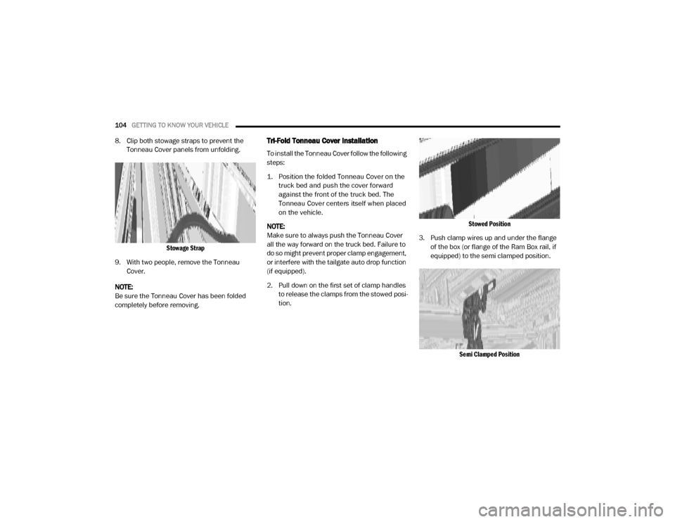
8. Clip both stowage straps to prevent the
Tonneau Cover panels from unfolding.
Stowage Strap
9. With two people, remove the Tonneau Cover.
NOTE:
Be sure the Tonneau Cover has been folded
completely before removing.Tri-Fold Tonneau Cover Installation
To install the Tonneau Cover follow the following
steps:
1. Position the folded Tonneau Cover on the truck bed and push the cover forward
against the front of the truck bed. The
Tonneau Cover centers itself when placed
on the vehicle.
NOTE:
Make sure to always push the Tonneau Cover
all the way forward on the truck bed. Failure to
do so might prevent proper clamp engagement,
or interfere with the tailgate auto drop function
(if equipped).
2. Pull down on the first set of clamp handles to release the clamps from the stowed posi -
tion.
Stowed Position
3. Push clamp wires up and under the flange of the box (or flange of the Ram Box rail, if
equipped) to the semi clamped position.
Semi Clamped Position
20_DJD2_OM_EN_USC_t.book Page 104
Page 295 of 553
STARTING AND OPERATING293
(Continued)
(Continued)
When you move the gear selector into
REVERSE with ParkSense turned off, the
instrument cluster display will show "Off" on
the vehicle graphic arcs for as long as the
vehicle is in REVERSE.
ParkSense, when on, will reduce the volume
of the radio when it is sounding a tone.
Clean the ParkSense sensors regularly,
taking care not to scratch or damage them.
The sensors must not be covered with ice,
snow, slush, mud, dirt or debris. Failure to do
so can result in the system not working prop
-
erly. The ParkSense system might not detect
an obstacle behind the fascia/bumper, or it
could provide a false indication that an
obstacle is behind the fascia/bumper.
Ensure the ParkSense system is off if objects
such as bicycle carriers, trailer hitches, etc.,
are placed within 18 inches (45 cm) of the
rear fascia/bumper while driving the vehicle.
Failure to do so can result in the system
misinterpreting a close obstacle as a sensor
problem, causing the "Rear ParkSense
Unavailable Service Required" message to
appear in the instrument cluster display.
On vehicles equipped with a tailgate, Park -
Sense should be disabled when the tailgate
is in the lowered or open position and the
vehicle is in REVERSE. A lowered tailgate
could provide a false indication that an
obstacle is behind the vehicle.
WARNING!
Drivers must be careful when backing up
even when using ParkSense. Always check
carefully behind your vehicle, look behind
you, and be sure to check for pedestrians,
animals, other vehicles, obstructions, and
blind spots before backing up. You are
responsible for safety and must continue to
pay attention to your surroundings. Failure
to do so can result in serious injury or
death.
Before using ParkSense, it is strongly
recommended that the ball mount and
hitch ball assembly is disconnected from
the vehicle when the vehicle is not used for
towing. Failure to do so can result in injury
or damage to vehicles or obstacles
because the hitch ball will be much closer
to the obstacle than the rear fascia when
the loudspeaker sounds the continuous
tone. Also, the sensors could detect the ball
mount and hitch ball assembly, depending
on its size and shape, giving a false indica -
tion that an obstacle is behind the vehicle.
CAUTION!
ParkSense is only a parking aid and it is
unable to recognize every obstacle,
including small obstacles. Parking curbs
might be temporarily detected or not
detected at all. Obstacles located above or
below the sensors will not be detected
when they are in close proximity.
WARNING! (Continued)
5
20_DJD2_OM_EN_USC_t.book Page 293
Page 300 of 553
298STARTING AND OPERATING
Service Required" or the "Front/Rear Park -
Sense Unavailable Wipe Sensors" message.
When the gear selector is moved into REVERSE,
a vehicle graphic will show in the instrument
cluster display, along with the display overlay
“Wipe Sensors.” If the system needs service,
the display overlay will read “Service.” Under
this condition, ParkSense will not operate.
If "Front/Rear ParkSense Unavailable Wipe
Sensors" appears in the instrument cluster
display make sure the outer surface and the
underside of the rear fascia/bumper is clean
and clear of snow, ice, mud, dirt or other
obstruction, and then cycle the ignition. If the
message continues to appear, see an autho -
rized dealer.
If "Front/Rear ParkSense Unavailable Service
Required" appears in the instrument cluster
display, see an authorized dealer.
Cleaning The ParkSense System
Clean the ParkSense sensors with water, car
wash soap and a soft cloth. Do not use rough or
hard cloths. Do not scratch or poke the sensors.
Otherwise, you could damage the sensors.
ParkSense System Usage Precautions
NOTE:
Ensure that the front and rear bumpers are
free of snow, ice, mud, dirt and debris to keep
the ParkSense system operating properly.
Jackhammers, large trucks, and other vibra -
tions could affect the performance of Park -
Sense.
When you move the gear selector to the
REVERSE position and Front or Rear Park -
Sense is turned off, the instrument cluster
display will show "Off" on the vehicle graphic
arcs. This vehicle graphic will be displayed for
as long as the vehicle is in REVERSE.
ParkSense, when on, will reduce the volume
of the radio when it is sounding a tone.
Clean the ParkSense sensors regularly,
taking care not to scratch or damage them.
The sensors must not be covered with ice,
snow, slush, mud, dirt or debris. Failure to do
so can result in the system not working prop -
erly. The ParkSense system might not detect an obstacle behind or in front of the fascia/
bumper, or it could provide a false indication
that an obstacle is behind or in front of the
fascia/bumper.
Use the ParkSense switch to turn the Park
-
Sense system off if obstacles such as bicycle
carriers, trailer hitches, etc. are placed within
18 inches (45 cm) from the rear fascia/
bumper. Failure to do so can result in the
system misinterpreting a close obstacle as a
sensor problem, causing the “Front/Rear
ParkSense Unavailable Service Required”
message to be appear in the instrument
cluster display.
On vehicles equipped with a tailgate, Park -
Sense should be disabled when the tailgate
is in the lowered or open position. A lowered
tailgate could provide a false indication that
an obstacle is behind the vehicle.
20_DJD2_OM_EN_USC_t.book Page 298
Page 306 of 553
304STARTING AND OPERATING
The ParkView Camera is located in the center of
the tailgate handle.
NOTE:
If snow, ice, mud, or any foreign substance
builds up on the camera lens, clean the lens,
rinse with water, and dry with a soft cloth. Do
not cover the lens.
Zoom View
When the Rear View Camera image is
being displayed, and the vehicle
speed is below 8 mph (13 km/h)
while in any gear selector position,
Zoom View is available. By pressing the “magni -
fying glass” icon in the upper left of the display screen, the image will zoom in to four times the
standard view. Pressing the icon a second time
will return the view to the standard Backup
Camera display.
When Zoom View is selected while the vehicle is
in REVERSE, then shifted to DRIVE, the camera
delay view will display the standard Backup
Camera view. If the vehicle is then returned to
REVERSE gear from DRIVE, the Zoom View
selection will automatically resume.
Shifting to NEUTRAL from any gear will maintain
the selected view (Zoom or Standard) as long as
the vehicle is below 8 mph (13 km/h).
If the vehicle is in PARK, Zoom View is available
until the gear selector is placed in DRIVE or
REVERSE.
NOTE:
If the vehicle is in DRIVE, NEUTRAL, or
REVERSE, and speed is greater than or equal
to 8 mph (13 km/h), Zoom View is unavail
-
able and the icon will appear gray.
While in Zoom View, the guidelines will not be
visible.
AUX Camera — If Equipped
Your vehicle may be equipped with one or two
AUX Cameras, which display rearview and side
view images from the trailer on the touch-
screen.
Activation
The AUX Camera is activated by first pressing
the Backup Camera, Cargo Camera (if
equipped), or Surround View Camera (if
equipped) button on the touchscreen, followed
by the AUX button located in the upper left
corner of the rearview display. The AUX camera
can also be activated when the vehicle is in
REVERSE by pressing the AUX button.
If equipped with two AUX Cameras, you can
switch between each camera by then pressing
the AUX1 or AUX2 buttons on the Trailer Camera
display.
AUX1 Camera Button
AUX2 Camera ButtonCAUTION!
To avoid vehicle damage, ParkView should
only be used as a parking aid. The ParkView
camera is unable to view every obstacle or
object in your drive path.
To avoid vehicle damage, the vehicle must
be driven slowly when using ParkView to be
able to stop in time when an obstacle is
seen. It is recommended that the driver
look frequently over his/her shoulder when
using ParkView.
20_DJD2_OM_EN_USC_t.book Page 304
Page 307 of 553
STARTING AND OPERATING305
Deactivation
The AUX Camera is deactivated by pressing the
“X” in the upper right corner of the touchscreen.
This will return the display back to the previ -
ously displayed screen.
NOTE:
If the AUX button is pressed and no AUX
Camera is connected, the touchscreen will
display a blue screen along with the message
“Camera System Unavailable.” The screen
can be exited out by pressing the “X” in the
upper right hand corner. This will return the
display back to the previously displayed
screen.
Zoom View is not available with the AUX
Camera feature.
The display will always default to the Trailer
Camera display (AUX 1).
SURROUND VIEW CAMERA SYSTEM — IF
EQUIPPED
Your vehicle may be equipped with the
Surround View Camera System that allows you
to see an on-screen image of the surroundings
and top view of your vehicle whenever the gear selector is put into REVERSE or manually acti
-
vated via the Uconnect system. The top view of
the vehicle will show which doors are open. The
image will be displayed on the touchscreen
display along with a caution note “Check Entire
Surroundings” across the top of the screen.
After five seconds, this note will disappear. The
Surround View Camera System is comprised of
four sequential cameras located in the front
grille, rear tailgate and side mirrors.
NOTE:
The Surround View Camera System has
programmable settings that may be selected
through the Uconnect System. Refer to “Ucon -
nect Settings” in “Multimedia” for further infor -
mation.
When the vehicle is shifted into REVERSE, the
rear camera view and top view is the default
view of the system (Automatic Activation).
When the vehicle is shifted out of REVERSE
(with camera delay turned on), the camera
image will continue to be displayed for up to 10
seconds after shifting out of REVERSE unless
the vehicle speed exceeds 8 mph (13 km/h),
the vehicle is shifted into PARK or the ignition is
placed in the OFF position. There is a touch -screen button “X” to disable the display of the
camera image.
When the vehicle is shifted out of REVERSE
(with camera delay turned off), the surround
view camera mode is exited and the last known
screen appears again.
While the “Rear View” camera is displayed and
guidelines are enabled, active guidelines are
overlaid on the image to illustrate the width of
the vehicle, including the side view mirrors and
its projected backup path based on the steering
wheel position.
Different colored zones indicate the distance to
the rear of the vehicle.
The following table shows the approximate
distances for each zone:
Zone Distance To The Rear
Of The Vehicle
Red 0 - 1 ft (0 - 30 cm)
Yellow 1 ft - 6.5 ft
(30 cm - 2 m)
Green 6.5 ft or greater
(2 m or greater)
5
20_DJD2_OM_EN_USC_t.book Page 305
Page 347 of 553

IN CASE OF EMERGENCY345
Removing The Spare Tire
1. Remove the spare tire before attempting to
jack up the truck. Attach the lug wrench to
the extension tubes with the curved angle
facing away from the vehicle. Insert the
extension tube through the access hole
between the lower tailgate and the top of
the bumper and into the winch mechanism
tube.
Winch Mechanism Tube
Inserting The Extension Tubes Into The Access Hole
2. Rotate the lug wrench handle counterclock -
wise until the spare tire is on the ground
with enough cable slack to allow you to pull
it out from under the vehicle.
Rotating The Lug Wrench Handle
3. Pull the spare tire out from under the vehicle to gain access to the spare tire
retainer.
Pulling The Spare Tire Out
WARNING!
After using the jack and tools, always reinstall
them in the original carrier and location.
While driving you may experience abrupt
stopping, rapid acceleration or sharp turns. A
loose jack, tools, bracket or other objects in
the vehicle may move around with force,
resulting in serious injury.
6
20_DJD2_OM_EN_USC_t.book Page 345
Page 353 of 553

IN CASE OF EMERGENCY351
2. Lift the spare tire with one hand to give
clearance to tilt the retainer at the end of
the cable and position it properly across the
wheel opening.
Pushing The Retainer Through The Center Of The Wheel And Positioning It
3. Attach the lug wrench to the extension
tubes with the curved angle facing away
from the vehicle. Insert the extensions
through the access hole between the lower
tailgate and the top of the bumper and into
the winch mechanism tube.
Lug Wrench And Extension Tubes Assembled And In Position
4. Rotate the lug wrench handle clockwise
until the wheel is drawn into place against
the underside of the vehicle. Continue to
rotate until you feel the winch mechanism
slip, or click three or four times. It cannot be
overtightened. Push against the tire several
times to ensure it is firmly in place.
Rotating The Lug Wrench Handle
NOTE:
The winch mechanism is designed for use with
the jack extension tube only. Use of an air
wrench or other power tools is not recom-
mended and can damage the winch.
6
20_DJD2_OM_EN_USC_t.book Page 351
Page 410 of 553

408SERVICING AND MAINTENANCE
exhaust after-treatment system work together
to achieve the EPA Heavy Duty Diesel Engine
Emissions Standards. These systems are seam -
lessly integrated into your vehicle and managed
by the Cummins Powertrain Control Module
(PCM). The PCM manages engine combustion
to allow the exhaust system’s catalyst to trap
and burn Particulate Matter (PM) pollutants,
with no input or interaction on your part.
If the engine is allowed to idle or the truck is
driven on low engine speed drive cycles for
more than two hours, the system will automati -
cally enter an emissions operating mode that
will increase the engine idle speed to 900 RPM
(1050 RPM for Chassis Cab). While in this
mode, which is designed to help maintain the
Diesel Particulate Filter, the engine idle speed
will return to normal when the brake pedal is
applied. A small change in engine tone or a
slight change in engine performance while
accelerating may also be noticeable at speeds
below 20 mph (32 kmh). This operating mode
may last for up to an hour of idle time, or around
20 minutes of driving time.
Additionally, your vehicle has the ability to alert
you to additional maintenance required on your
truck or engine. Refer to “Instrument Cluster Display” in
“Getting To Know Your Instrument Panel” for
further information.
Diesel Exhaust Fluid
Diesel Exhaust Fluid (DEF) sometimes known
simply by the name of its active component,
UREA—is a key component of selective catalytic
reduction (SCR) systems, which help diesel
vehicles meet stringent emission regulations.
DEF is a liquid reducing agent that reacts with
engine exhaust in the presence of a catalyst to
convert smog-forming nitrogen oxides (NOx)
into harmless nitrogen and water vapor.
Refer to “Fluids And Lubricants” in “Technical
Specification” for further information.
You can receive assistance in locating DEF in
the United States by calling 866-RAM-INFO (866-726-4636). In Canada call
1–800–465–2001 (English) or
1–800–387–9983 (French)
You can receive assistance in locating DEF by
contacting an authorized dealer.
Body Lubrication
Locks and all body pivot points, including such
items as seat tracks, door hinge pivot points
and rollers, liftgate, tailgate, decklid, sliding
doors and hood hinges, should be lubricated
periodically with a lithium based grease, such
as Mopar Spray White Lube to ensure quiet,
easy operation and to protect against rust and
wear. Prior to the application of any lubricant,
the parts concerned should be wiped clean to
remove dust and grit; after lubricating, excess
oil and grease should be removed. Particular
attention should also be given to hood latching
components to ensure proper function. When
performing other underhood services, the hood
latch, release mechanism and safety catch
should be cleaned and lubricated.
The external lock cylinders should be lubricated
twice a year, preferably in the Autumn and
Spring. Apply a small amount of a high quality
lubricant, such as Mopar Lock Cylinder Lubri
-
cant directly into the lock cylinder.
WARNING!
A hot exhaust system can start a fire if you
park over materials that can burn. Such
materials might be grass or leaves coming
into contact with your exhaust system. Do not
park or operate your vehicle in areas where
your exhaust system can contact anything
that can burn.
20_DJD2_OM_EN_USC_t.book Page 408
Page 542 of 553
540
INDEX
A
Adaptive Cruise Control (ACC) (Cruise
Control)
.......................................................... 275
Adding Engine Coolant (Antifreeze)............... 413
Adding Fuel.......................................... 312, 313
Additives, Fuel............................................... 446AdjustDown
........................................................... 34
Forward....................................................... 34
Rearward..................................................... 34
Up................................................................ 34
Adjustable Pedals............................................ 43
Air BagAir Bag Operation
...................................... 184
Air Bag Warning Light................................ 181Enhanced Accident Response......... 189, 371
Event Data Recorder (EDR)....................... 371
If Deployment Occurs................................ 188Knee Impact Bolsters................................ 184
Maintaining Your Air Bag System.............. 189
Maintenance............................................. 189Redundant Air Bag Warning Light.............182
Transporting Pets...................................... 208
Air Bag Light............................... 130, 181, 209
Air Cleaner, Engine (Engine Air Cleaner
Filter)
................................................... 398, 419
Air Conditioner Maintenance........................ 400
Air Conditioner Refrigerant........................... 400
Air Conditioner System................................. 400
Air Conditioning......................................... 57, 68
Air Conditioning Filter..............................70, 401
Air Conditioning System................................... 68Air Conditioning, Operating Tips....................... 69
Air Filter........................................................ 398
Air PressureTires
......................................................... 429
AlarmPanic
........................................................... 15
Security Alarm....................................25, 131
Alterations/ModificationsVehicle
......................................................... 12Android Auto................................................. 533
Antifreeze (Engine Coolant)................. 412, 451
Capacites................................................. 451Disposal................................................... 414
Anti-Lock Brake System (ABS)...................... 144
Anti-Lock Warning Light................................ 136Apple CarPlay................................................ 533
Assist, Hill Start............................................. 151
Audio Systems (Radio).................................. 458
Auto Down Power Windows............................. 71
Automatic Door Locks...................................... 31
Automatic Headlights.......................................51
Automatic Tailgate Release.............................75
Automatic Temperature Control (ATC)..............68
Automatic Transmission....................... 233, 418
Adding Fluid.............................................. 418
Fluid And Filter Change............................. 418Fluid Change............................................. 418
Fluid Level Check............................. 416, 417
Fluid Type...............................416, 454, 457
Shifting..................................................... 237
Special Additives...................................... 416
Automatic Transmission Limp Home Mode... 236
AUX Camera......................................... 304, 311
Auxiliary Driving Systems.............................. 153
Axle Fluid.....................................418, 454, 457Axle Lubrication............................................ 418
B
Back-Up
......................................................... 302
Back-Up Camera........................................... 302
Bar, Stabilizer/Sway System......................... 253Battery................................................. 132, 395
Blanket..................................................... 223
Charging System Light.............................. 132Keyless Key Fob Replacement....................15
Battery Saver Feature......................................53
20_DJD2_OM_EN_USC_t.book Page 540