tailgate Ram 2500 2020 Owner's Manual
[x] Cancel search | Manufacturer: RAM, Model Year: 2020, Model line: 2500, Model: Ram 2500 2020Pages: 553, PDF Size: 21.99 MB
Page 5 of 553

3
Power Mirrors — If Equipped ...................... 45
Power Convex Mirror Switch —
If Equipped ................................................... 46 Trailer Towing Mirrors — If Equipped ......... 46
Heated Mirrors — If Equipped ..................... 47
Tilt Side Mirrors In Reverse —
If Equipped ................................................... 47 Power Folding Outside Mirrors For
Standard And Trailer Tow — If Equipped .... 47 Illuminated Vanity Mirror — If Equipped ..... 48
EXTERIOR LIGHTS.................................................49
Multifunction Lever ...................................... 49
Headlight Switch .......................................... 49
Daytime Running Lights (DRLs) —
If Equipped ................................................... 49 High/Low Beam Switch ............................... 50
Automatic High Beam Headlamp Control —
If Equipped ................................................... 50 Flash-To-Pass ............................................... 51
Automatic Headlights — If Equipped ......... 51
Directional LED Headlamp System — If
Equipped ...................................................... 51 Parking Lights And Panel Lights ................. 51
Headlights On With Wipers (Available With
Automatic Headlights Only) ......................... 51 Headlight Delay ............................................ 51
Lights-On Reminder ..................................... 52 Front Fog Lights — If Equipped .................. 52
Turn Signals ................................................ 52
Lane Change Assist — If Equipped ............. 52
Cargo Lights/Trailer Spotter Lights With
Bed Lights — If Equipped............................. 52 Battery Saver ............................................... 53
INTERIOR LIGHTS ................................................ 53
Courtesy Lights ............................................ 53
Illuminated Entry ......................................... 55
WINDSHIELD WIPERS AND WASHERS............. 55
Windshield Wipers ....................................... 55
Rain Sensing Wipers — If Equipped ........... 56
CLIMATE CONTROLS ........................................... 57
Manual Climate Control Overview .............. 57
Automatic Climate Control Overview .......... 61
Climate Control Functions........................... 68
Automatic Temperature Control (ATC) ....... 68
Operating Tips ............................................. 69
WINDOWS ............................................................ 70
Power Windows ........................................... 70
Wind Buffeting ............................................ 72
POWER SUNROOF — IF EQUIPPED .................... 72
Single Pane Power Sunroof —
If Equipped ................................................... 72
HOOD .................................................................... 74
To Open The Hood ...................................... 74
To Close The Hood ....................................... 75 TAILGATE ...............................................................75
Opening ........................................................ 75
Closing.......................................................... 75
Bed Step — If Equipped ............................... 75
GARAGE DOOR OPENER — IF EQUIPPED ..........76
Before You Begin Programming
HomeLink® .................................................. 77 Canadian/Gate Operator Programming..... 79
Using HomeLink®........................................ 80
Security ........................................................ 80
Troubleshooting Tips ................................... 80
General Information .................................... 81
INTERNAL EQUIPMENT ........................................82
Storage ......................................................... 82
Cupholders .................................................. 87
Electrical Power Outlets .............................. 88
Power Inverter — If Equipped ..................... 90
Wireless Charging Pad — If Equipped ....... 91
Overhead Sunglass Storage ....................... 92
PICKUP BOX .........................................................92
Cargo Camera — If Equipped ...................... 93
RAMBOX — IF EQUIPPED .....................................94
RamBox Integrated Box Side Storage
Bins............................................................... 95 RamBox Safety Warning ............................. 96
Bed Divider — If Equipped ........................... 96
Bed Rail Tie-Down System —
If Equipped .................................................. 98
20_DJD2_OM_EN_USC_t.book Page 3
Page 6 of 553

4
SLIDE-IN CAMPERS .......................................... 100 Camper Applications .................................100
EASY-OFF TAILGATE ......................................... 100
Disconnecting The Rear Camera And
Remote Keyless Entry ...............................100 Removing The Tailgate .............................. 101
Locking Tailgate .........................................101
TRI-FOLD TONNEAU COVER — IF EQUIPPED .. 101
Tri-Fold Tonneau Cover Removal ..............102
Tri-Fold Tonneau Cover Installation ..........104
Tri-Fold Tonneau Cover Cleaning ..............107
GETTING TO KNOW YOUR INSTRUMENT PANEL
BASE / MIDLINE INSTRUMENT CLUSTER —
GAS ENGINE ....................................................... 108
Base / Midline Instrument Cluster
Descriptions — Gas Engine .......................109
PREMIUM INSTRUMENT CLUSTER —
GAS ENGINE ....................................................... 111
Premium Instrument Cluster Descriptions —
Gas Engine .................................................112
BASE INSTRUMENT CLUSTER — DIESEL
ENGINE ............................................................... 113
Base Instrument Cluster Descriptions —
Diesel Engine .............................................114
PREMIUM INSTRUMENT CLUSTER — DIESEL
ENGINE ................................................................ 116
Premium Instrument Cluster Descriptions —
Diesel Engine .............................................117 INSTRUMENT CLUSTER DISPLAY ................... 117
Instrument Cluster Display Controls......... 118
Oil Life Reset ............................................. 119
Display Menu Items ................................... 119
Diesel Messages And Warnings — 6.7L
Cummins Diesel Engine ............................ 124 Battery Saver On/Battery Saver Mode
Message — Electrical Load Reduction
Actions — If Equipped ................................ 128
WARNING LIGHTS AND MESSAGES ................130
Red Warning Lights ................................... 130
Yellow Warning Lights ............................... 133
Yellow Indicator Lights .............................. 137
Green Indicator Lights ............................... 140
White Indicator Lights ............................... 141
Blue Indicator Lights.................................. 141
ONBOARD DIAGNOSTIC SYSTEM — OBD II..... 141
Onboard Diagnostic System (OBD II)
Cybersecurity ............................................. 142
EMISSIONS INSPECTION AND MAINTENANCE
PROGRAMS......................................................... 142
SAFETY
SAFETY FEATURES .............................................144
Anti-Lock Brake System (ABS) ................. 144
Electronic Brake Control (EBC) System .... 145 AUXILIARY DRIVING SYSTEMS ........................ 153
Blind Spot Monitoring (BSM) —
If Equipped ................................................ 153 Forward Collision Warning (FCW) With
Mitigation — If Equipped ........................... 160 Tire Pressure Monitoring System
(TPMS) ........................................................ 163
OCCUPANT RESTRAINT SYSTEMS ................. 171
Occupant Restraint Systems Features ... 171
Important Safety Precautions ................... 171
Seat Belt Systems .................................... 172
Supplemental Restraint Systems (SRS)... 181
Child Restraints ......................................... 190
Transporting Pets ...................................... 208
SAFETY TIPS ....................................................... 208
Transporting Passengers .......................... 208
Exhaust Gas .............................................. 208
Safety Checks You Should Make Inside
The Vehicle ................................................ 209 Periodic Safety Checks You Should Make
Outside The Vehicle ................................... 210
20_DJD2_OM_EN_USC_t.book Page 4
Page 16 of 553
14GETTING TO KNOW YOUR VEHICLE
TIP:
When viewing a topic, tap the star icon to add it
to your Favorites, for easy access in the future.
KEYS
Key Fob
Your vehicle uses a keyless ignition system. The
ignition system consists of a key fob and a
START/STOP push button ignition system. The
Remote Keyless Entry (RKE) system consists of
a key fob and Keyless Enter-N-Go feature.
NOTE:
The key fob may not be found if it is located next
to a mobile phone, laptop or other electronic
device; these devices may block the key fob’s
wireless signal.
The key fob allows you to lock or unlock all
doors, tailgate, and the RamBox (if equipped),
as well as release the tailgate, and activate the
Panic Alarm from distances up to approximately
66 ft (20 m). The key fob does not need to be
pointed at the vehicle to activate the system. NOTE:
In the ON/RUN position, all key fob buttons
will work until the vehicle reaches 2 mph
(4 km/h).
The key fob should not be placed next to the
wireless charging pad (if equipped).
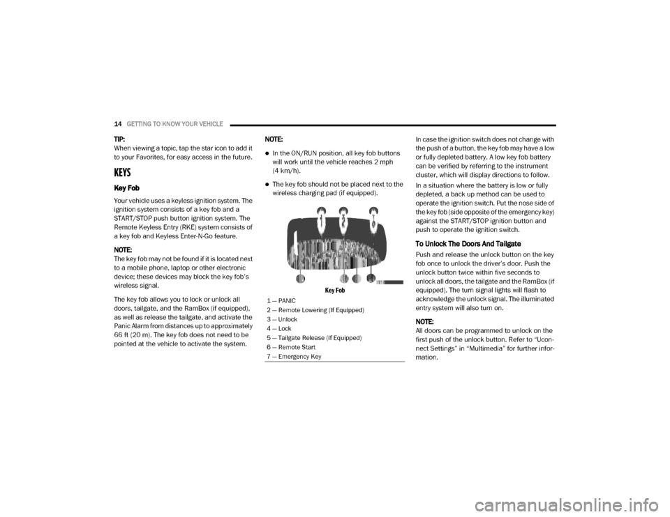
Key Fob
In case the ignition switch does not change with
the push of a button, the key fob may have a low
or fully depleted battery. A low key fob battery
can be verified by referring to the instrument
cluster, which will display directions to follow.
In a situation where the battery is low or fully
depleted, a back up method can be used to
operate the ignition switch. Put the nose side of
the key fob (side opposite of the emergency key)
against the START/STOP ignition button and
push to operate the ignition switch.
To Unlock The Doors And Tailgate
Push and release the unlock button on the key
fob once to unlock the driver’s door. Push the
unlock button twice within five seconds to
unlock all doors, the tailgate and the RamBox (if
equipped). The turn signal lights will flash to
acknowledge the unlock signal. The illuminated
entry system will also turn on.
NOTE:
All doors can be programmed to unlock on the
first push of the unlock button. Refer to “Ucon
-
nect Settings” in “Multimedia” for further infor -
mation.
1 — PANIC
2 — Remote Lowering (If Equipped)
3 — Unlock
4 — Lock
5 — Tailgate Release (If Equipped)
6 — Remote Start
7 — Emergency Key
20_DJD2_OM_EN_USC_t.book Page 14
Page 17 of 553
GETTING TO KNOW YOUR VEHICLE15
To Lock The Doors And Tailgate
Push and release the lock button on the key fob
to lock all doors, the tailgate, and the RamBox
(if equipped). The turn signal lights will flash and
the horn will chirp to acknowledge the signal.
Sound Horn With Remote Key Lock — If
Equipped
This feature will cause the horn to chirp when
the doors are locked with the key fob. This
feature can be turned on or turned off through
the Uconnect settings.
NOTE:
Pushing the lock button on the key fob while you
are in the vehicle will activate the vehicle secu -
rity alarm system. Opening a door with the
vehicle security alarm system activated will
cause the alarm to sound. Push the unlock
button to deactivate the vehicle security alarm
system.
Refer to “Vehicle Security Alarm” in this chapter
for further information.
Using The Panic Alarm
To turn the Panic Alarm feature on or off, push
the Panic button on the key fob. When the Panic
Alarm is activated, the turn signals will flash, the horn will pulse on and off, and the interior lights
will turn on.
The Panic Alarm will stay on for three minutes
unless you turn it off by either pushing the Panic
button a second time or drive the vehicle at a
speed of 15 mph (24 km/h) or greater.
NOTE:
The interior lights will turn off if you place the
ignition in the ACC or ON/RUN position while
the Panic Alarm is activated. However, the
exterior lights and horn will remain on.
You may need to be less than 35 ft (11 m)
from the vehicle when using the key fob to
turn off the Panic Alarm due to the radio
frequency noises emitted by the system.
Replacing The Battery In The Key Fob With
Remote Control
The replacement battery model is one CR2032
battery.
NOTE:
Perchlorate Material — special handling may
apply. See
www.dtsc.ca.gov/hazard -
ouswaste/perchlorate for further
information.
Do not touch the battery terminals that are
on the back housing or the printed circuit
board.
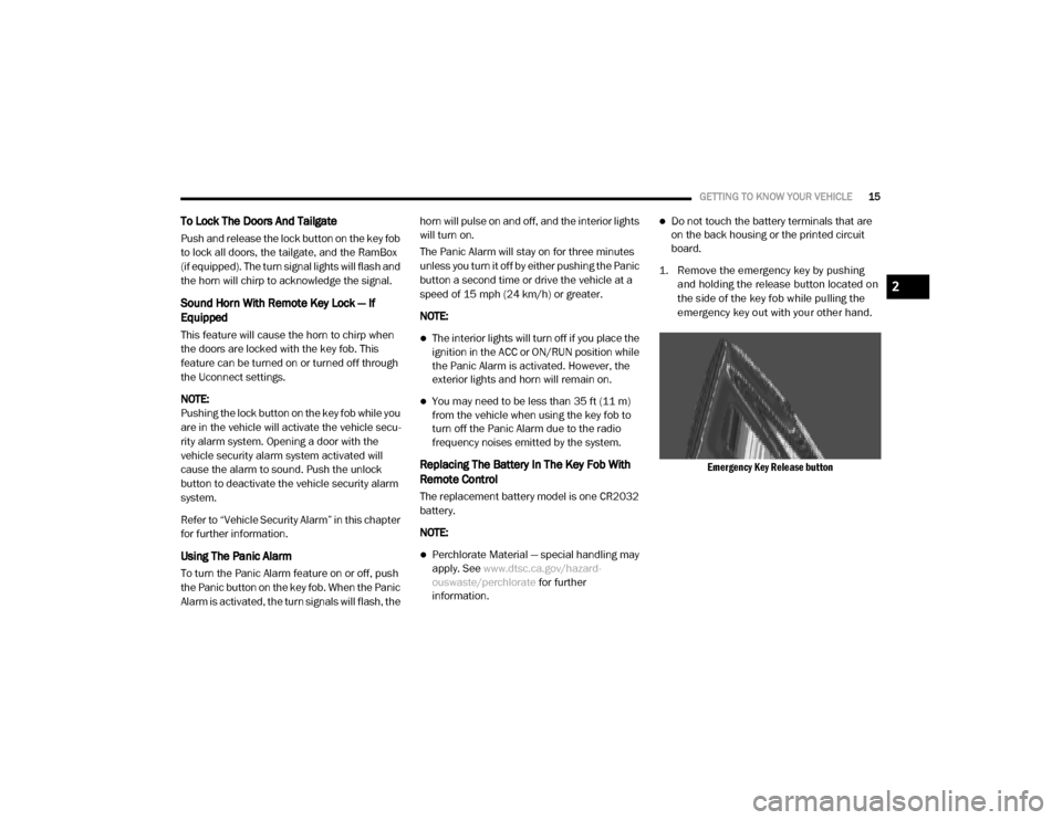
1. Remove the emergency key by pushing and holding the release button located on
the side of the key fob while pulling the
emergency key out with your other hand.
Emergency Key Release button
2
20_DJD2_OM_EN_USC_t.book Page 15
Page 27 of 553

GETTING TO KNOW YOUR VEHICLE25
NOTE:
Duplication of key fobs may be performed at an
authorized dealer. This procedure consists of
programming a blank key fob to the vehicle
electronics. A blank key fob is one that has
never been programmed.
When having the Sentry Key Immobilizer
System serviced, bring all vehicle keys with you
to an authorized dealer.
General Information
The following regulatory statement applies to all
Radio Frequency (RF) devices equipped in this
vehicle:
This device complies with Part 15 of the FCC
Rules and with Innovation, Science and
Economic Development Canada license-exempt
RSS standard(s). Operation is subject to the
following two conditions:
1. This device may not cause harmful interfer
-
ence, and
2. This device must accept any interference received, including interference that may
cause undesired operation.
Le présent appareil est conforme aux CNR
d`Innovation, Science and Economic Develop -
ment applicables aux appareils radio exempts
de licence. L'exploitation est autorisée aux deux
conditions suivantes:
1. l'appareil ne doit pas produire de brouil -
lage, et
2. l'utilisateur de l'appareil doit accepter tout brouillage radioélectrique subi, même si le
brouillage est susceptible d'en comprom -
ettre le fonctionnement.
La operación de este equipo está sujeta a las
siguientes dos condiciones:
1. es posible que este equipo o dispositivo no cause interferencia perjudicial y
2. este equipo o dispositivo debe aceptar cual -
quier interferencia, incluyendo la que
pueda causar su operación no deseada. NOTE:
Changes or modifications not expressly
approved by the party responsible for compli
-
ance could void the user’s authority to operate
the equipment.
VEHICLE SECURITY ALARM
The vehicle security alarm monitors the vehicle
doors, tailgate, and ignition for unauthorized
operation. When the vehicle security alarm is
activated, interior switches for door locks are
disabled. The system will turn the horn off after
29 seconds, 5 seconds between cycles, up to 8
cycles if the trigger remains active and then the
vehicle security alarm will rearm itself.
To Arm The System
Follow these steps to arm the vehicle security
alarm:
1. Remove the key from the ignition system. Refer to "Starting The Engine" in "Starting
And Operating" for further information.
Make sure the vehicle ignition system is OFF.
For vehicles equipped with Keyless
Enter-N-Go — Ignition, always remember to
place the ignition in the OFF position.
CAUTION! (Continued)
2
20_DJD2_OM_EN_USC_t.book Page 25
Page 46 of 553
44GETTING TO KNOW YOUR VEHICLE
Headlight glare from vehicles behind you can be
reduced by moving the small control under the
mirror to the night position (toward the rear of
the vehicle). The mirror should be adjusted
while set in the day position (toward the wind -
shield).
Adjusting Rearview Mirror
Automatic Dimming Mirror — If Equipped
The mirror head can be adjusted up, down, left,
and right for various drivers. The mirror should
be adjusted to center on the view through the
rear window.
This mirror automatically adjusts for headlight
glare from vehicles behind you. NOTE:
The Automatic Dimming feature is disabled
when the vehicle is in REVERSE to improve rear
view viewing.
The Automatic Dimming feature can be turned
on or off through the touchscreen.
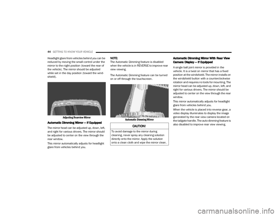
Automatic Dimming Mirror
Automatic Dimming Mirror With Rear View
Camera Display — If Equipped
A single ball joint mirror is provided in the
vehicle. It is a twist on mirror that has a fixed
position at the windshield. The mirror installs on
the windshield button with a counterclockwise
rotation and requires no tools for mounting. The
mirror head can be adjusted up, down, left, and
right for various drivers. The mirror should be
adjusted to center on the view through the rear
window.
This mirror automatically adjusts for headlight
glare from vehicles behind you.
When the vehicle is placed into reverse gear, a
video display illuminates to display the image
generated by the rear view camera located on
the tailgate handle. The auto dimming feature is
also disabled to improve rear view viewing.
CAUTION!
To avoid damage to the mirror during
cleaning, never spray any cleaning solution
directly onto the mirror. Apply the solution
onto a clean cloth and wipe the mirror clean.
20_DJD2_OM_EN_USC_t.book Page 44
Page 77 of 553
GETTING TO KNOW YOUR VEHICLE75
To Close The Hood
Lower the hood to approximately 12 inches
(30 cm) from the engine compartment and drop
it. Make sure that the hood is completely
closed.
TAILGATE
Opening
The power tailgate may be opened by pushing
the tailgate release pad located on the tailgate
door.
The tailgate damper strut will lower the tailgate
to the open position (if equipped).
Electronic Tailgate Release — If Equipped
The key fob may be equipped with an
electronic release feature for the tail-
gate, allowing hands-free tailgate
opening. To activate, push and
release the Tailgate Release button on the key
fob twice within five seconds. The tailgate door
will unlatch, and slowly lower into the open posi -
tion.
If equipped, a button on the center overhead
console inside the vehicle can be used to
release the tailgate.
NOTE:
The Tri-Fold Tonneau Cover (if equipped) may
prevent Electronic Tailgate Release if installed.
The Tonneau Cover must be removed or folded
up before releasing the tailgate. Refer to “Tri-Fold Tonneau Cover — If Equipped” in this
chapter for further information.
Closing
To close the tailgate, push it upward until both
sides are latched.
NOTE:
Pull back on the tailgate firmly after closing to
ensure it is securely latched.
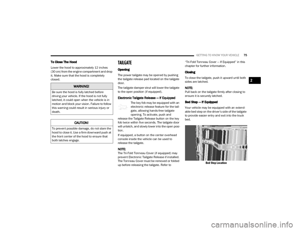
Bed Step — If Equipped
Your vehicle may be equipped with an extend
-
able bed step on the driver’s side of the tailgate
to provide easier entry and exit into the truck
bed.
Bed Step Location
WARNING!
Be sure the hood is fully latched before
driving your vehicle. If the hood is not fully
latched, it could open when the vehicle is in
motion and block your vision. Failure to follow
this warning could result in serious injury or
death.
CAUTION!
To prevent possible damage, do not slam the
hood to close it. Use a firm downward push at
the front center of the hood to ensure that
both latches engage.
2
20_DJD2_OM_EN_USC_t.book Page 75
Page 78 of 553
76GETTING TO KNOW YOUR VEHICLE
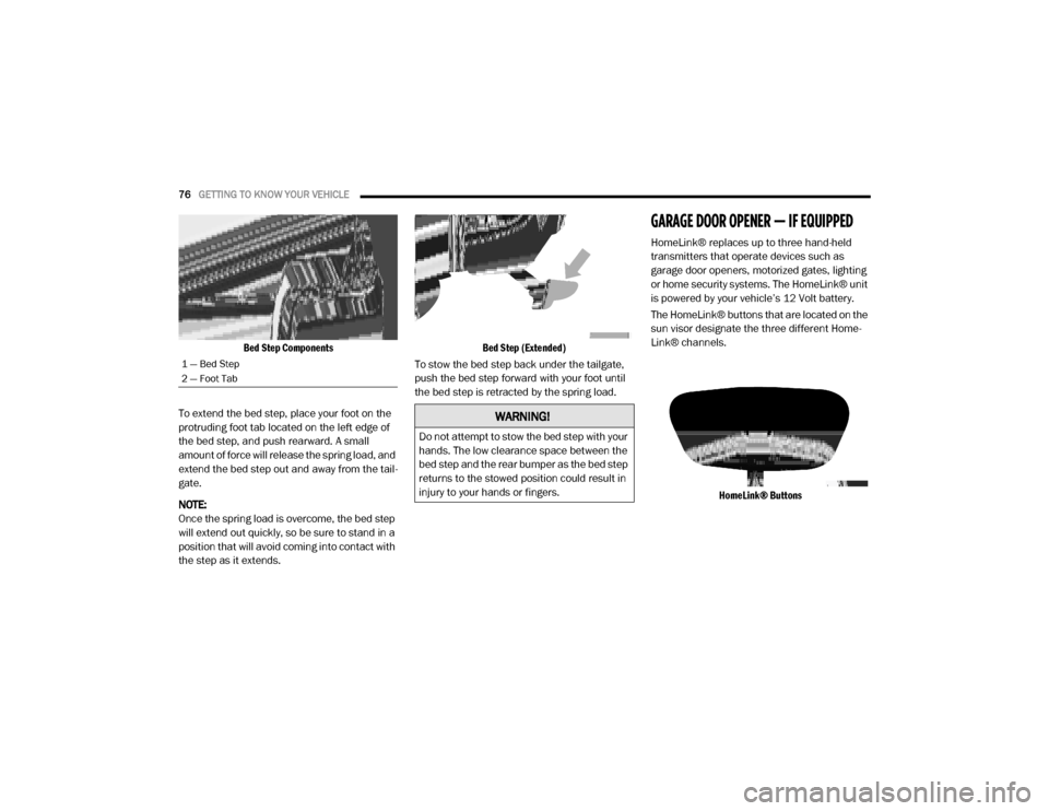
Bed Step Components
To extend the bed step, place your foot on the
protruding foot tab located on the left edge of
the bed step, and push rearward. A small
amount of force will release the spring load, and
extend the bed step out and away from the tail -
gate.
NOTE:
Once the spring load is overcome, the bed step
will extend out quickly, so be sure to stand in a
position that will avoid coming into contact with
the step as it extends.
Bed Step (Extended)
To stow the bed step back under the tailgate,
push the bed step forward with your foot until
the bed step is retracted by the spring load.
GARAGE DOOR OPENER — IF EQUIPPED
HomeLink® replaces up to three hand-held
transmitters that operate devices such as
garage door openers, motorized gates, lighting
or home security systems. The HomeLink® unit
is powered by your vehicle’s 12 Volt battery.
The HomeLink® buttons that are located on the
sun visor designate the three different Home -
Link® channels.
HomeLink® Buttons
1 — Bed Step
2 — Foot Tab
WARNING!
Do not attempt to stow the bed step with your
hands. The low clearance space between the
bed step and the rear bumper as the bed step
returns to the stowed position could result in
injury to your hands or fingers.
20_DJD2_OM_EN_USC_t.book Page 76
Page 102 of 553

100GETTING TO KNOW YOUR VEHICLE
SLIDE-IN CAMPERS
Camper Applications
Certain truck models are not recommended for
slide-in campers. To determine if your vehicle is
excluded, please refer to the “Consumer Infor -
mation Truck-Camper Loading” document at
www.ramtrucks.com . For safety reasons, follow
all instructions in this important document.
NOTE:
When a cap or pickup camper is installed on a
vehicle, an alternate Center High-Mounted Stop
Light (CHMSL) must be provided.
EASY-OFF TAILGATE
To simplify mounting of a camper unit with an
overhang, the tailgate can be removed.
NOTE:
The electric connector at the bottom of the tail -
gate must be disconnected prior to removing
the tailgate.
Disconnecting The Rear Camera And
Remote Keyless Entry
1. Open the tailgate to access the rear camera or Remote Keyless Entry
connector bracket located on the rear sill.
Connector Bracket
2. Remove the connector bracket from the sill by pushing inward in the locking tab.
Locking Tab
3. Disconnect the chassis wiring harness, ensuring the connector bracket does not
fall into the sill.
4. Connect the chassis plug and bracket (provided in the glove compartment) to the
chassis wiring harness and insert the
bracket back into the sill.
5. Connect the tailgate plug (provided in the glove compartment) to the tailgate wiring
harness to ensure that the terminals do not
corrode.
6. Tape the tailgate harness and bracket against the forward-facing surface of the
tailgate. This will prevent damaging the
connector and bracket when storing or rein -
stalling the tailgate.
WARNING!
To avoid inhaling carbon monoxide, which is
deadly, the exhaust system on vehicles
equipped with “Cap or Slide-In Campers”
should extend beyond the overhanging
camper compartment and be free of leaks.
20_DJD2_OM_EN_USC_t.book Page 100
Page 103 of 553
GETTING TO KNOW YOUR VEHICLE101
Removing The Tailgate
1. Disconnect the wiring harness for the rear
camera and or power locks (if equipped).
NOTE:
Refer to “Disconnecting The Rear Camera And
Remote Keyless Entry” in this section.
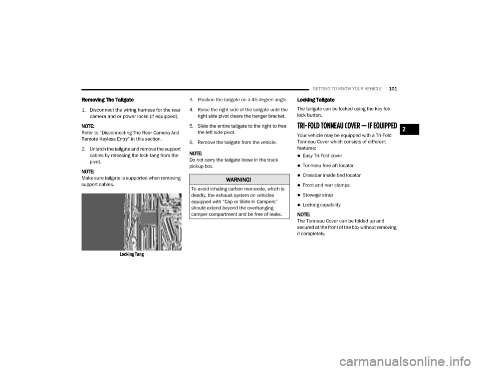
2. Unlatch the tailgate and remove the support cables by releasing the lock tang from the
pivot.
NOTE:
Make sure tailgate is supported when removing
support cables.
Locking Tang
3. Position the tailgate on a 45 degree angle.
4. Raise the right side of the tailgate until the
right side pivot clears the hanger bracket.
5. Slide the entire tailgate to the right to free the left side pivot.
6. Remove the tailgate from the vehicle.
NOTE:
Do not carry the tailgate loose in the truck
pickup box.
Locking Tailgate
The tailgate can be locked using the key fob
lock button.
TRI-FOLD TONNEAU COVER — IF EQUIPPED
Your vehicle may be equipped with a Tri-Fold
Tonneau Cover which consists of different
features:
Easy Tri-Fold cover
Tonneau fore aft locator
Crossbar inside bed locator
Front and rear clamps
Stowage strap
Locking capability
NOTE:
The Tonneau Cover can be folded up and
secured at the front of the box without removing
it completely.
WARNING!
To avoid inhaling carbon monoxide, which is
deadly, the exhaust system on vehicles
equipped with “Cap or Slide-In Campers”
should extend beyond the overhanging
camper compartment and be free of leaks.
2
20_DJD2_OM_EN_USC_t.book Page 101