turn signal Ram 2500 2020 Owner's Guide
[x] Cancel search | Manufacturer: RAM, Model Year: 2020, Model line: 2500, Model: Ram 2500 2020Pages: 553, PDF Size: 21.99 MB
Page 301 of 553
STARTING AND OPERATING299
LANESENSE — IF EQUIPPED
LaneSense Operation
The LaneSense system is operational at speeds
above 37 mph (60 km/h) and below 112 mph
(180 km/h). It uses a forward looking camera to
detect lane markings and measure vehicle posi -
tion within the lane boundaries.
When both lane markings are detected and the
driver unintentionally drifts out of the lane while
no turn signal has been applied OR the driver
departs the lane on the opposite side of the
applied turn signal (if the left turn signal is applied and the vehicle departs to the right), the
LaneSense system provides a haptic warning in
the form of torque applied to the steering wheel
to prompt the driver to remain within the lane
boundaries. The LaneSense system will also
provide a visual warning through the instrument
cluster display to prompt the driver to remain
within the lane boundaries.
The driver may manually override the haptic
warning by applying torque into the steering
wheel at any time.
When only a single lane marking is detected
and the driver unintentionally drifts across that
lane marking (no turn signal applied), the Lane
-
Sense system provides a visual warning
through the instrument cluster display to
prompt the driver to remain within the lane.
When only a single lane marking is detected, a
haptic (torque) warning will not be provided.
NOTE:
When operating conditions have been met, the
LaneSense system will monitor if the driver’s
hands are on the steering wheel and provides
an audible and visual warning to the driver
when the driver’s hands are not detected on the
steering wheel. The system will cancel if the
driver does not return their hands to the wheel.
WARNING!
Drivers must be careful when backing up
even when using ParkSense. Always check
carefully behind your vehicle, look behind
you, and be sure to check for pedestrians,
animals, other vehicles, obstructions, and
blind spots before backing up. You are
responsible for safety and must continue to
pay attention to your surroundings. Failure
to do so can result in serious injury or
death.
Before using ParkSense, it is strongly
recommended that the ball mount and
hitch ball assembly is disconnected from
the vehicle when the vehicle is not used for
towing. Failure to do so can result in injury
or damage to vehicles or obstacles
because the hitch ball will be much closer
to the obstacle than the rear fascia when
the loudspeaker sounds the continuous
tone. Also, the sensors could detect the ball
mount and hitch ball assembly, depending
on its size and shape, giving a false indica -
tion that an obstacle is behind the vehicle.
CAUTION!
ParkSense is only a parking aid and it is
unable to recognize every obstacle,
including small obstacles. Parking curbs
might be temporarily detected or not
detected at all. Obstacles located above or
below the sensors will not be detected
when they are in close proximity.
The vehicle must be driven slowly when
using ParkSense in order to be able to stop
in time when an obstacle is detected. It is
recommended that the driver looks over
his/her shoulder when using ParkSense.
5
20_DJD2_OM_EN_USC_t.book Page 299
Page 304 of 553
302STARTING AND OPERATING
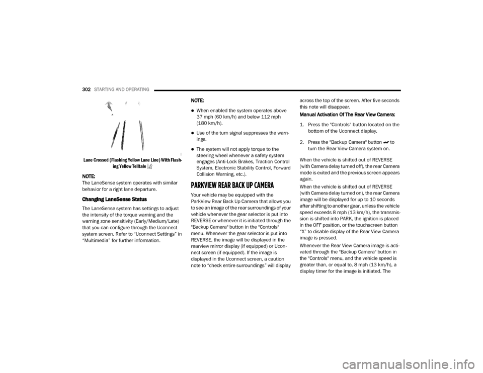
Lane Crossed (Flashing Yellow Lane Line) With Flash -
ing Yellow Telltale
NOTE:
The LaneSense system operates with similar
behavior for a right lane departure.
Changing LaneSense Status
The LaneSense system has settings to adjust
the intensity of the torque warning and the
warning zone sensitivity (Early/Medium/Late)
that you can configure through the Uconnect
system screen. Refer to “Uconnect Settings” in
“Multimedia” for further information. NOTE:
When enabled the system operates above
37 mph (60 km/h) and below 112 mph
(180 km/h).
Use of the turn signal suppresses the warn
-
ings.
The system will not apply torque to the
steering wheel whenever a safety system
engages (Anti-Lock Brakes, Traction Control
System, Electronic Stability Control, Forward
Collision Warning, etc.).
PARKVIEW REAR BACK UP CAMERA
Your vehicle may be equipped with the
ParkView Rear Back Up Camera that allows you
to see an image of the rear surroundings of your
vehicle whenever the gear selector is put into
REVERSE or whenever it is initiated through the
"Backup Camera" button in the "Controls"
menu. Whenever the gear selector is put into
REVERSE, the image will be displayed in the
rearview mirror display (if equipped) or Ucon -
nect screen (if equipped). If the image is
displayed in the Uconnect screen, a caution
note to “check entire surroundings” will display across the top of the screen. After five seconds
this note will disappear.
Manual Activation Of The Rear View Camera:
1. Press the "Controls" button located on the
bottom of the Uconnect display.
2. Press the "Backup Camera" button to turn the Rear View Camera system on.
When the vehicle is shifted out of REVERSE
(with Camera delay turned off), the rear Camera
mode is exited and the previous screen appears
again.
When the vehicle is shifted out of REVERSE
(with Camera delay turned on), the rear Camera
image will be displayed for up to 10 seconds
after shifting to another gear, unless the vehicle
speed exceeds 8 mph (13 km/h), the transmis- sion is shifted into PARK, the ignition is placed
in the OFF position, or the touchscreen button
“X” to disable display of the Rear View Camera
image is pressed.
Whenever the Rear View Camera image is acti -
vated through the "Backup Camera" button in
the "Controls" menu, and the vehicle speed is
greater than, or equal to, 8 mph (13 km/h), a display timer for the image is initiated. The
20_DJD2_OM_EN_USC_t.book Page 302
Page 329 of 553

STARTING AND OPERATING327
* The suggested selection depends and may
change depending on the customer prefer -
ences for braking performance. Condition of the
trailer brakes, driving and road state may also
affect the selection.
Display Messages
The trailer brake control interacts with the
instrument cluster display. Display messages,
along with a single chime, will be displayed
when a malfunction is determined in the trailer
connection, trailer brake control, or on the
trailer. Refer to “Instrument Cluster Display” in
“Getting To Know Your Instrument Panel” for
further information. NOTE:
An aftermarket controller may be available
for use with trailers with air or elec
-
tric-over-hydraulic trailer brake systems. To
determine the type of brakes on your trailer
and the availability of controllers, check with
your trailer manufacturer or dealer.
Removal of the ITBM will cause errors and it
may cause damage to the electrical system
and electronic modules of the vehicle. See
your authorized dealer if an aftermarket
module is to be installed.
Towing Requirements — Trailer Lights And
Wiring
Whenever you pull a trailer, regardless of the
trailer size, stoplights and turn signals on the
trailer are required for motoring safety.
The Trailer Tow Package may include a four- and
seven-pin wiring harness. Use a factory
approved trailer harness and connector.
NOTE:
Do not cut or splice wiring into the vehicle’s
wiring harness.
The electrical connections are all complete to
the vehicle but you must mate the harness to a
trailer connector. Refer to the following illustra -
tions.
Light Electric Heavy Electric Light EOHHeavy EOH
Type of Trailer Brakes Electric Trailer Brakes Electric Trailer Brakes Electric over Hydraulic
Trailer BrakesElectric over Hydraulic
Trailer Brakes
Load *Under 10,000 lbs *Above 10,000 lbs *Under 10,000 lbs *Above 10,000 lbs
WARNING!
Connecting a trailer that is not compatible
with the ITBM system may result in reduced
or complete loss of trailer braking. There may
be a increase in stopping distance or trailer
instability which could result in personal
injury.
CAUTION!
Connecting a trailer that is not compatible
with the ITBM system may result in reduced
or complete loss of trailer braking. There may
be a increase in stopping distance or trailer
instability which could result in damage to
your vehicle, trailer, or other property.
5
20_DJD2_OM_EN_USC_t.book Page 327
Page 340 of 553
338
IN CASE OF EMERGENCY
HAZARD WARNING FLASHERS
The Hazard Warning Flashers switch
is located on the upper switch bank
just below the radio.
NOTE:
If your vehicle is equipped with a 12–inch Ucon -
nect display, the Hazard Warning Flashers
switch is located above the display.
Push the switch to turn on the Hazard Warning
Flashers. When the switch is activated, all direc -
tional turn signals will flash on and off to warn
oncoming traffic of an emergency. Push the
switch a second time to turn off the Hazard
Warning Flashers.
This is an emergency warning system and it
should not be used when the vehicle is in
motion. Use it when your vehicle is disabled and
it is creating a safety hazard for other motorists.
When you must leave the vehicle to seek assis -
tance, the Hazard Warning Flashers will
continue to operate even though the ignition is
placed in the OFF position. NOTE:
With extended use the Hazard Warning
Flashers may wear down your battery.
ASSIST AND SOS SYSTEM — IF EQUIPPED
NOTE:
Depending on the vehicles trim level, the over
-
head console may vary.
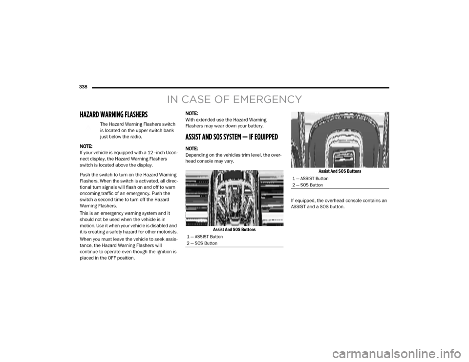
Assist And SOS Buttons Assist And SOS Buttons
If equipped, the overhead console contains an
ASSIST and a SOS button.
1 — ASSIST Button
2 — SOS Button
1 — ASSIST Button
2 — SOS Button
20_DJD2_OM_EN_USC_t.book Page 338
Page 343 of 553
IN CASE OF EMERGENCY341
SOS Call System Limitations
Vehicles sold in Mexico DO NOT have SOS Call
system capabilities.
SOS or other emergency line operators in
Mexico may not answer or respond to SOS
system calls.
If the SOS Call system detects a malfunction,
any of the following may occur at the time the
malfunction is detected, and at the beginning of
each ignition cycle:
The overhead console light located between
the ASSIST and SOS buttons will continuously
be illuminated red.
The Device Screen will display the following
message: “Vehicle device requires service.
Please contact your dealer.”
An In-Vehicle Audio message will state
“Vehicle device requires service. Please
contact your dealer.” Even if the SOS Call system is fully functional,
factors beyond FCA US LLC’s control may
prevent or stop the SOS Call system operation.
These include, but are not limited to, the
following factors:
Delayed accessories mode is active.
The ignition is in the OFF position.
The vehicle’s electrical systems are not
intact.
The SOS Call system software and/or hard
-
ware are damaged during a crash.
The vehicle battery loses power or becomes
disconnected during a vehicle crash.
LTE (voice/data) or 4G (data) network and/or
Global Positioning Satellite signals are
unavailable or obstructed.
Equipment malfunction at the SOS operator
facility.
Operator error by the SOS operator.
LTE (voice/data) or 4G (data) network
congestion.
Weather.
Buildings, structures, geographic terrain, or
tunnels.
WARNING!
Ignoring the overhead console light could
mean you will not have SOS Call services. If
the overhead console light is illuminated,
have an authorized dealer service the SOS
Call system immediately.
The Occupant Restraint Control module
turns on the air bag Warning Light on the
instrument panel if a malfunction in any
part of the system is detected. If the Air Bag
Warning Light is illuminated, have an
authorized dealer service the Occupant
Restraint Control system immediately.
WARNING!
ALWAYS obey traffic laws and pay attention to
the road. ALWAYS drive safely with your hands
on the steering wheel. You have full
responsibility and assume all risks related to
the use of the features and applications in
this vehicle. Only use the features and
applications when it is safe to do so. Failure
to do so may result in an accident involving
serious injury or death.
6
20_DJD2_OM_EN_USC_t.book Page 341
Page 374 of 553
372IN CASE OF EMERGENCY
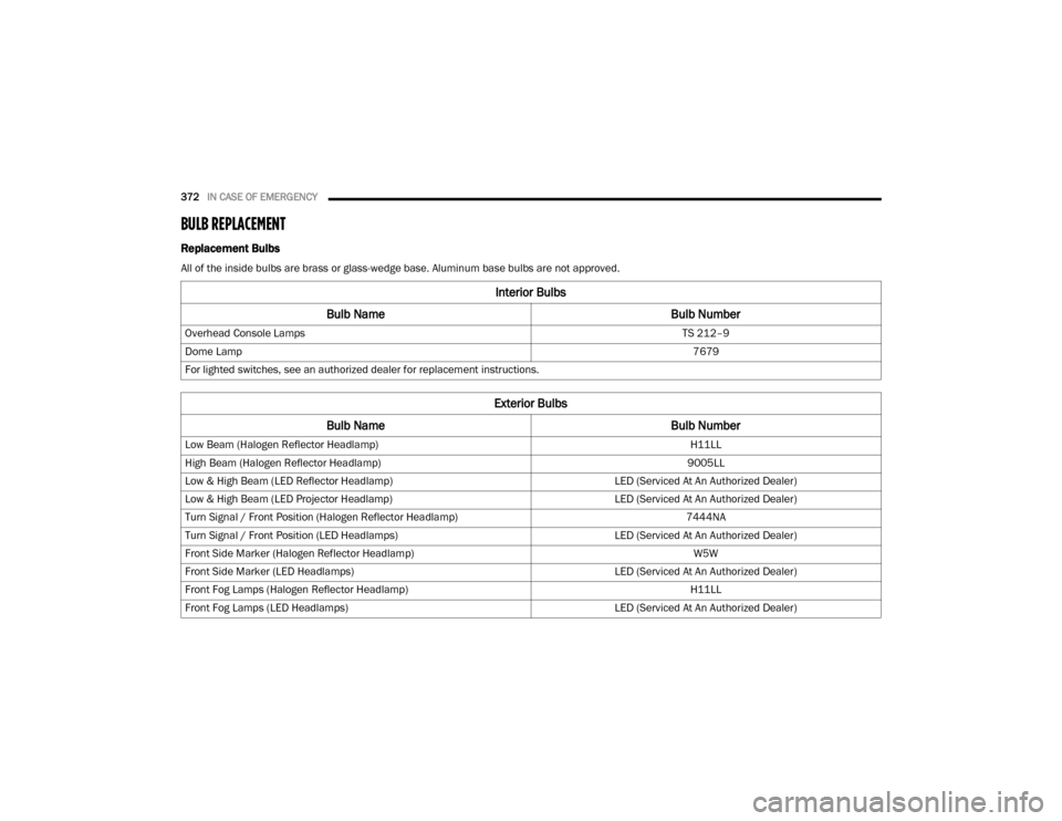
BULB REPLACEMENT
Replacement Bulbs
All of the inside bulbs are brass or glass-wedge base. Aluminum base bulbs are not approved.
Interior Bulbs
Bulb Name Bulb Number
Overhead Console Lamps TS 212–9
Dome Lamp 7679
For lighted switches, see an authorized dealer for replacement instructions.
Exterior Bulbs
Bulb Name Bulb Number
Low Beam (Halogen Reflector Headlamp) H11LL
High Beam (Halogen Reflector Headlamp) 9005LL
Low & High Beam (LED Reflector Headlamp) LED (Serviced At An Authorized Dealer)
Low & High Beam (LED Projector Headlamp) LED (Serviced At An Authorized Dealer)
Turn Signal / Front Position (Halogen Reflector Headlamp) 7444NA
Turn Signal / Front Position (LED Headlamps) LED (Serviced At An Authorized Dealer)
Front Side Marker (Halogen Reflector Headlamp) W5W
Front Side Marker (LED Headlamps) LED (Serviced At An Authorized Dealer)
Front Fog Lamps (Halogen Reflector Headlamp) H11LL
Front Fog Lamps (LED Headlamps) LED (Serviced At An Authorized Dealer)
20_DJD2_OM_EN_USC_t.book Page 372
Page 378 of 553
376IN CASE OF EMERGENCY
4. Reach through the access hole of the wheel
house splash shield and disengage the side
marker socket by rotating counterclockwise
a quarter turn.
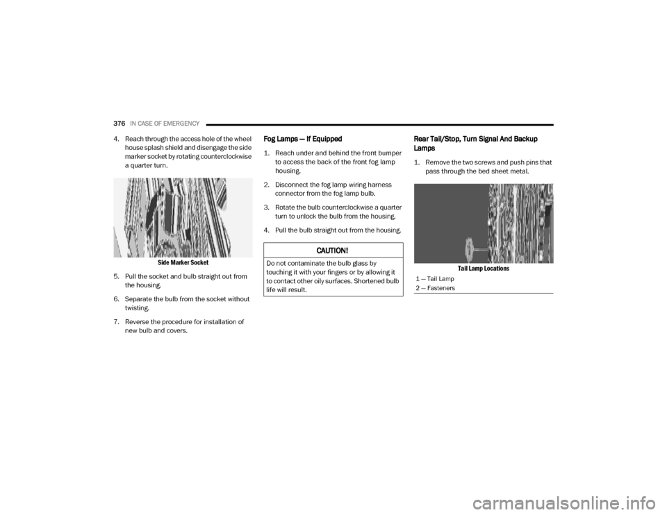
Side Marker Socket
5. Pull the socket and bulb straight out from the housing.
6. Separate the bulb from the socket without twisting.
7. Reverse the procedure for installation of new bulb and covers.Fog Lamps — If Equipped
1. Reach under and behind the front bumper to access the back of the front fog lamp
housing.
2. Disconnect the fog lamp wiring harness connector from the fog lamp bulb.
3. Rotate the bulb counterclockwise a quarter turn to unlock the bulb from the housing.
4. Pull the bulb straight out from the housing.
Rear Tail/Stop, Turn Signal And Backup
Lamps
1. Remove the two screws and push pins that pass through the bed sheet metal.
Tail Lamp Locations
CAUTION!
Do not contaminate the bulb glass by
touching it with your fingers or by allowing it
to contact other oily surfaces. Shortened bulb
life will result.
1 — Tail Lamp
2 — Fasteners
20_DJD2_OM_EN_USC_t.book Page 376
Page 485 of 553
MULTIMEDIA483
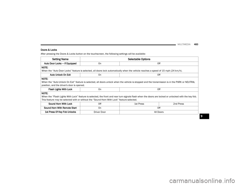
Doors & Locks
After pressing the Doors & Locks button on the touchscreen, the following settings will be available:
Setting Name Selectable Options
Auto Door Locks — If EquippedOn Off
NOTE:
When the “Auto Door Locks” feature is selected, all doors lock automatically when the vehicle reaches a speed of 15 mph (24 km/h). Auto Unlock On Exit On Off
NOTE:
When the “Auto Unlock On Exit” feature is selected, all doors unlock when the vehicle is stopped and the transmission is in the PARK or NEUTRAL
position, and the driver's door is opened. Flash Lights With Lock On Off
NOTE:
When the “Flash Lights With Lock” feature is selected, the front and rear turn signals flash when the doors are locked or unlocked with the key fob.
This feature may be selected with or without the “Sound Horn With Lock” feature selected. Sound Horn With Lock Off1st Press 2nd Press
Sound Horn With Remote Start On Off
1st Press Of Key Fob Unlocks Driver Door All Doors
9
20_DJD2_OM_EN_USC_t.book Page 483
Page 504 of 553
502MULTIMEDIA
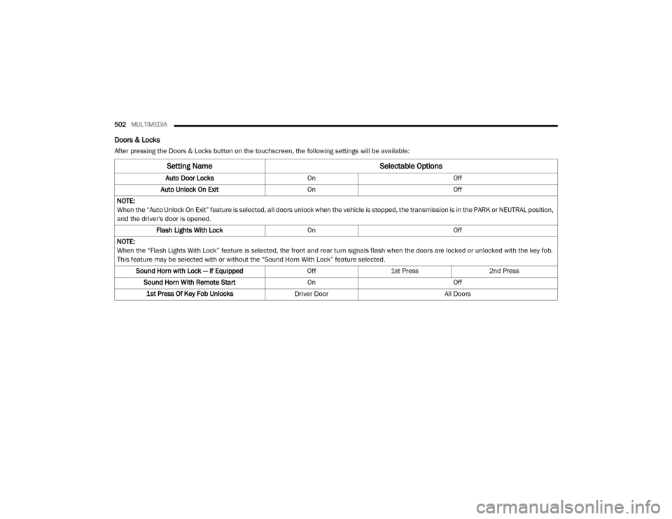
Doors & Locks
After pressing the Doors & Locks button on the touchscreen, the following settings will be available:
Setting Name Selectable Options
Auto Door LocksOn Off
Auto Unlock On Exit OnOff
NOTE:
When the “Auto Unlock On Exit” feature is selected, all doors unlock when the vehicle is stopped, the transmission is in the PARK or NEUTRAL position,
and the driver's door is opened. Flash Lights With Lock OnOff
NOTE:
When the “Flash Lights With Lock” feature is selected, the front and rear turn signals flash when the doors are locked or unlocked with the key fob.
This feature may be selected with or without the “Sound Horn With Lock” feature selected. Sound Horn with Lock — If Equipped Off1st Press 2nd Press
Sound Horn With Remote Start OnOff
1st Press Of Key Fob Unlocks Driver Door All Doors
20_DJD2_OM_EN_USC_t.book Page 502
Page 544 of 553
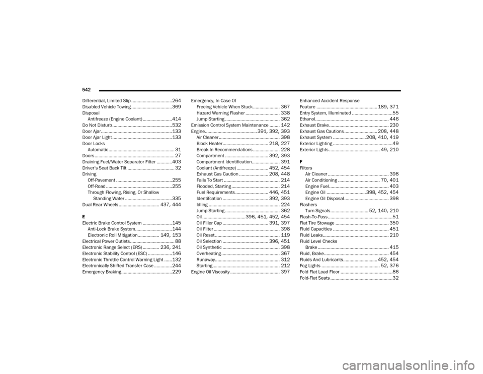
542
Differential, Limited Slip
................................ 264
Disabled Vehicle Towing................................ 369
Disposal Antifreeze (Engine Coolant)
....................... 414
Do Not Disturb............................................... 532
Door Ajar........................................................ 133
Door Ajar Light............................................... 133Door LocksAutomatic
.................................................... 31
Doors............................................................... 27Draining Fuel/Water Separator Filter............ 403
Driver’s Seat Back Tilt..................................... 32
DrivingOff-Pavement
............................................ 255
Off-Road.................................................... 255Through Flowing, Rising, Or Shallow Standing Water
..................................... 335
Dual Rear Wheels................................ 437, 444
E
Electric Brake Control System
....................... 145
Anti-Lock Brake System............................. 144
Electronic Roll Mitigation................. 149, 153
Electrical Power Outlets................................... 88Electronic Range Select (ERS)............. 236, 241
Electronic Stability Control (ESC)...................146
Electronic Throttle Control Warning Light...... 132
Electronically Shifted Transfer Case.............. 244
Emergency Braking........................................ 229
Emergency, In Case OfFreeing Vehicle When Stuck
..................... 367
Hazard Warning Flasher........................... 338
Jump Starting........................................... 362
Emission Control System Maintenance........ 142
Engine......................................... 391, 392, 393
Air Cleaner................................................ 398Block Heater.................................... 218, 227
Break-In Recommendations..................... 228
Compartment.................................. 392, 393Compartment Identification...................... 391
Coolant (Antifreeze)......................... 452, 454
Exhaust Gas Caution....................... 208, 448
Fails To Start............................................ 214
Flooded, Starting...................................... 214Fuel Requirements.......................... 446, 451
Identifcation.................................... 392, 393
Idling........................................................ 224
Jump Starting........................................... 362Oil..................................396, 451, 452, 454
Oil Filler Cap.................................... 391, 397
Oil Filter.................................................... 398
Oil Reset................................................... 119
Oil Selection.................................... 396, 451
Oil Synthetic............................................. 398
Overheating.............................................. 367
Runaway................................................... 312
Starting..................................................... 212
Engine Oil Viscosity....................................... 397
Enhanced Accident Response
Feature
................................................ 189, 371
Entry System, Illuminated................................55
Ethanol.......................................................... 446
Exhaust Brake............................................... 230
Exhaust Gas Cautions.......................... 208, 448
Exhaust System..........................208, 410, 419Exterior Lighting...............................................49
Exterior Lights........................................ 49, 210
F
FiltersAir Cleaner
................................................ 398
Air Conditioning................................. 70, 401
Engine Fuel............................................... 403
Engine Oil...............................398, 452, 454
Engine Oil Disposal................................... 398
FlashersTurn Signals
.............................. 52, 140, 210
Flash-To-Pass...................................................51
Flat Tire Stowage.......................................... 350
Fluid Capacities............................................ 451
Fluid Leaks.................................................... 210
Fluid Level ChecksBrake........................................................ 415
Fluid, Brake................................................... 454
Fluids And Lubricants........................... 452, 454
Fog Lights.............................................. 52, 376
Fold Flat Load Floor.........................................86
Fold-Flat Seats.................................................32
20_DJD2_OM_EN_USC_t.book Page 542