instrument panel Ram 2500 2020 Owner's Manual
[x] Cancel search | Manufacturer: RAM, Model Year: 2020, Model line: 2500, Model: Ram 2500 2020Pages: 553, PDF Size: 21.99 MB
Page 3 of 553

TABLE OF CONTENTS
1
2
3
4
5
6
7
8
9
10
11
1INTRODUCTION .............................................................................................................................11
2 G
E
TTING TO KNOW YOUR VEHICLE ..................................................................................13
3 GETTING TO KNOW YOUR INSTRUMENT PANEL ......................................................108
4 SAFETY .........................................................................................................................................144
5 STARTING AND OPERATING ................................................................................................ 211
6 IN CASE OF EMERGENCY .................................................................................................... 338
7 SERVICING AND MAINTENANCE ......................................................................................380
8 TECHNICAL SPECIFICATIONS ........................................................................................... 444
9 MULTIMEDIA .............................................................................................................................. 458
10 CUSTOMER ASSISTANCE ..................................................................................................... 536
11 INDEX ............................................................................................................................................ 540
20_DJD2_OM_EN_USC_t.book Page 1
Page 6 of 553

4
SLIDE-IN CAMPERS .......................................... 100 Camper Applications .................................100
EASY-OFF TAILGATE ......................................... 100
Disconnecting The Rear Camera And
Remote Keyless Entry ...............................100 Removing The Tailgate .............................. 101
Locking Tailgate .........................................101
TRI-FOLD TONNEAU COVER — IF EQUIPPED .. 101
Tri-Fold Tonneau Cover Removal ..............102
Tri-Fold Tonneau Cover Installation ..........104
Tri-Fold Tonneau Cover Cleaning ..............107
GETTING TO KNOW YOUR INSTRUMENT PANEL
BASE / MIDLINE INSTRUMENT CLUSTER —
GAS ENGINE ....................................................... 108
Base / Midline Instrument Cluster
Descriptions — Gas Engine .......................109
PREMIUM INSTRUMENT CLUSTER —
GAS ENGINE ....................................................... 111
Premium Instrument Cluster Descriptions —
Gas Engine .................................................112
BASE INSTRUMENT CLUSTER — DIESEL
ENGINE ............................................................... 113
Base Instrument Cluster Descriptions —
Diesel Engine .............................................114
PREMIUM INSTRUMENT CLUSTER — DIESEL
ENGINE ................................................................ 116
Premium Instrument Cluster Descriptions —
Diesel Engine .............................................117 INSTRUMENT CLUSTER DISPLAY ................... 117
Instrument Cluster Display Controls......... 118
Oil Life Reset ............................................. 119
Display Menu Items ................................... 119
Diesel Messages And Warnings — 6.7L
Cummins Diesel Engine ............................ 124 Battery Saver On/Battery Saver Mode
Message — Electrical Load Reduction
Actions — If Equipped ................................ 128
WARNING LIGHTS AND MESSAGES ................130
Red Warning Lights ................................... 130
Yellow Warning Lights ............................... 133
Yellow Indicator Lights .............................. 137
Green Indicator Lights ............................... 140
White Indicator Lights ............................... 141
Blue Indicator Lights.................................. 141
ONBOARD DIAGNOSTIC SYSTEM — OBD II..... 141
Onboard Diagnostic System (OBD II)
Cybersecurity ............................................. 142
EMISSIONS INSPECTION AND MAINTENANCE
PROGRAMS......................................................... 142
SAFETY
SAFETY FEATURES .............................................144
Anti-Lock Brake System (ABS) ................. 144
Electronic Brake Control (EBC) System .... 145 AUXILIARY DRIVING SYSTEMS ........................ 153
Blind Spot Monitoring (BSM) —
If Equipped ................................................ 153 Forward Collision Warning (FCW) With
Mitigation — If Equipped ........................... 160 Tire Pressure Monitoring System
(TPMS) ........................................................ 163
OCCUPANT RESTRAINT SYSTEMS ................. 171
Occupant Restraint Systems Features ... 171
Important Safety Precautions ................... 171
Seat Belt Systems .................................... 172
Supplemental Restraint Systems (SRS)... 181
Child Restraints ......................................... 190
Transporting Pets ...................................... 208
SAFETY TIPS ....................................................... 208
Transporting Passengers .......................... 208
Exhaust Gas .............................................. 208
Safety Checks You Should Make Inside
The Vehicle ................................................ 209 Periodic Safety Checks You Should Make
Outside The Vehicle ................................... 210
20_DJD2_OM_EN_USC_t.book Page 4
Page 14 of 553
12INTRODUCTION
HOW TO USE THIS MANUAL
Essential Information
Consult the Table of Contents to determine
which section contains the information you
desire.
Since the specification of your vehicle depends
on the items of equipment ordered, certain
descriptions and illustrations may differ from
your vehicle's equipment.
The detailed Index at the back of this Owner's
Manual contains a complete listing of all
subjects.
Symbols
Some vehicle components have colored labels
whose symbols indicate precautions to be
observed when using this component. Refer to
“Warning Lights and Messages” in “Getting To
Know Your Instrument Panel” for further infor -
mation on the symbols used in your vehicle.
WARNINGS AND CAUTIONS
This Owner’s Manual contains WARNINGS
against operating procedures that could result
in a collision, bodily injury and/or death. It also
contains CAUTIONS against procedures that
could result in damage to your vehicle. If you do
not read this entire Owner’s Manual, you may
miss important information. Observe all Warn -
ings and Cautions.
VAN CONVERSIONS/CAMPERS
The New Vehicle Limited Warranty does not
apply to body modifications or special equip -
ment installed by van conversion/camper
manufacturers/body builders. US residents
refer to the Warranty Information, Section
2.1.C. Canadian residents refer to the “What Is
Not Covered” section of the Warranty Informa -
tion. Such equipment includes video monitors,
VCRs, heaters, stoves, refrigerators, etc. For
warranty coverage and service on these items,
contact the applicable manufacturer.
Operating instructions for the special equip -
ment installed by the conversion/camper
manufacturer should also be supplied with your
vehicle. If these instructions are missing, please
contact an authorized dealer for assistance in obtaining replacement documents from the
applicable manufacturer.
For information on the Body Builder’s Guide
refer to
www.ramtrucks.com . This website
contains dimensional and technical specifica -
tions for your vehicle. It is intended for Second
Stage Manufacturer's technical support. For
service issues, contact an authorized dealer.
VEHICLE MODIFICATIONS/ALTERATIONS
WARNING!
Any modifications or alterations to this vehicle
could seriously affect its roadworthiness and
safety and may lead to a collision resulting in
serious injury or death.
20_DJD2_OM_EN_USC_t.book Page 12
Page 24 of 553
22GETTING TO KNOW YOUR VEHICLE
Le présent appareil est conforme aux CNR
d`Innovation, Science and Economic Develop -
ment applicables aux appareils radio exempts
de licence. L'exploitation est autorisée aux deux
conditions suivantes:
1. l'appareil ne doit pas produire de brouil -
lage, et
2. l'utilisateur de l'appareil doit accepter tout brouillage radioélectrique subi, même si le
brouillage est susceptible d'en comprom -
ettre le fonctionnement.
La operación de este equipo está sujeta a las
siguientes dos condiciones:
1. es posible que este equipo o dispositivo no cause interferencia perjudicial y
2. este equipo o dispositivo debe aceptar cual -
quier interferencia, incluyendo la que
pueda causar su operación no deseada.
NOTE:
Changes or modifications not expressly
approved by the party responsible for compli -
ance could void the user’s authority to operate
the equipment.REMOTE START— IF EQUIPPED (DIESEL)
This system uses the key fob to start
the engine conveniently from outside
the vehicle while still maintaining
security. The system has a range of
approximately 300 ft (91 m).
NOTE:
Obstructions between the vehicle and the
key fob may reduce this range.
The Remote Start system will wait for the
“Wait To Start” Indicator Light to extinguish
before cranking the engine. This allows time
for the intake heater to preheat the incoming
air, and is normal operation in cold weather.
Refer to “Wait To Start Light,” located in
“Warning Lights And Messages” in “Getting
To Know Your Instrument Panel” for more
information.
How To Use Remote Start
All of the following conditions must be met
before the engine will remote start:
Transmission in PARK
Doors closed
Hood closed
Hazard switch off
Brake switch inactive (brake pedal not
pushed)
Battery at an acceptable charge level
PANIC button not pushed
Fuel meets minimum requirement
Water In Fuel Indicator Light is not illumi -
nated
Wait To Start Light Indicator Light is not illu -
minated
Malfunction Indicator Light is not illuminated
20_DJD2_OM_EN_USC_t.book Page 22
Page 33 of 553
GETTING TO KNOW YOUR VEHICLE31
Automatic Door Locks — If Equipped
The auto door lock feature default condition is
enabled. When enabled, the door locks will lock
automatically when the vehicle's speed exceeds
15 mph (24 km/h). The auto door lock feature
can be enabled or disabled by an authorized
dealer per written request of the customer.
Please see an authorized dealer for service.
Automatic Doors Unlock — If Equipped
This feature unlocks all of the doors of the vehicle
when either front door is opened. This will occur
only after the vehicle has been shifted into the
PARK position after the vehicle has been driven
(shifted out of PARK and all doors closed).
Automatic Doors Unlock Programming — If
Equipped
The Automatic Doors Unlock feature can be
enabled or disabled as follows:
For vehicles not equipped with a touchscreen
radio, refer to “Instrument Cluster Display” in
“Getting To Know Your Instrument Panel” for
further information.
For vehicles equipped with a touchscreen
radio, refer to “Uconnect Settings” in “Multi -
media” for further information. NOTE:
Use the Auto Unlock Doors feature in accor
-
dance with local laws.
Child-Protection Door Lock
To provide a safer environment for children
riding in the rear seat, the rear doors (if
equipped) of your vehicle have the Child-Protec -
tion Door Lock system.
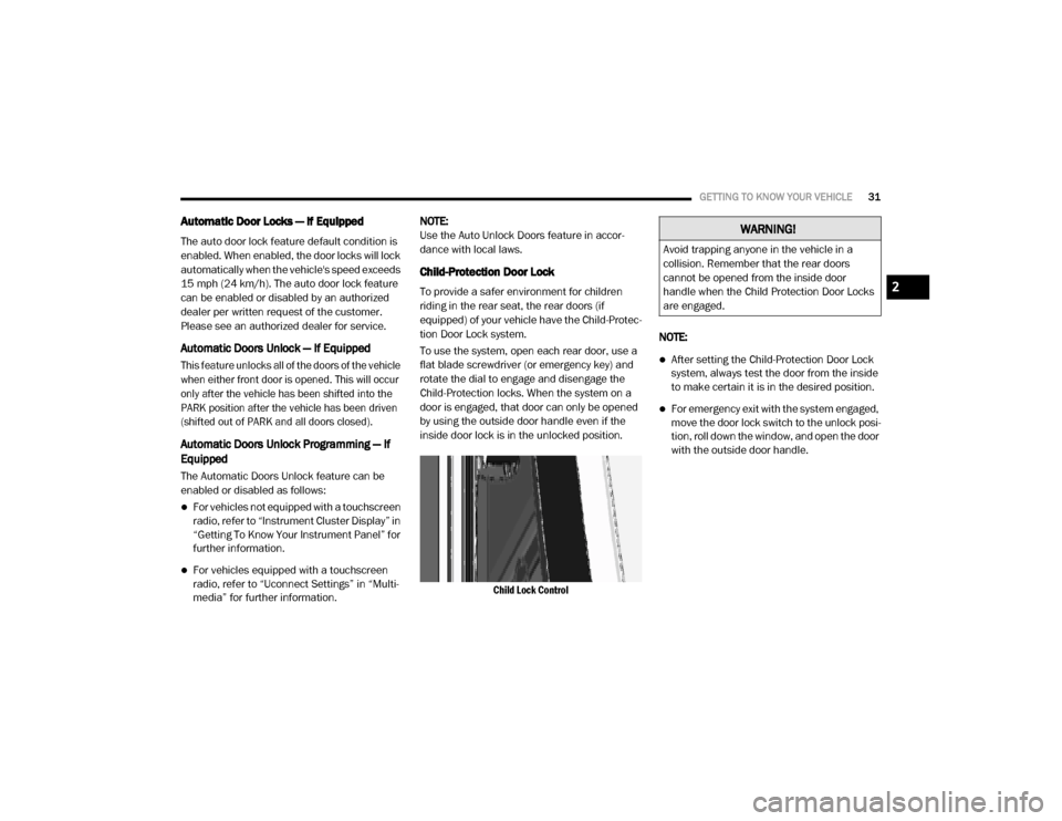
To use the system, open each rear door, use a
flat blade screwdriver (or emergency key) and
rotate the dial to engage and disengage the
Child-Protection locks. When the system on a
door is engaged, that door can only be opened
by using the outside door handle even if the
inside door lock is in the unlocked position.
Child Lock Control
NOTE:
After setting the Child-Protection Door Lock
system, always test the door from the inside
to make certain it is in the desired position.
For emergency exit with the system engaged,
move the door lock switch to the unlock posi
-
tion, roll down the window, and open the door
with the outside door handle.
WARNING!
Avoid trapping anyone in the vehicle in a
collision. Remember that the rear doors
cannot be opened from the inside door
handle when the Child Protection Door Locks
are engaged.
2
20_DJD2_OM_EN_USC_t.book Page 31
Page 38 of 553

36GETTING TO KNOW YOUR VEHICLE
4. Within five seconds, push and release
either of the memory buttons (1) or (2). The
instrument cluster display will show which
memory position has been set.
NOTE:
Memory profiles can be set without the vehicle
in PARK.
Linking And Unlinking The Remote Keyless
Entry Key Fob To Memory
Your key fob can be programmed to recall one
of two pre-programmed memory profiles by
pushing the unlock button on the key fob.
NOTE:
Before programming your key fob you must
select the “Personal Settings Linked to Key
Fob” feature through the Uconnect Settings.
Refer to “Uconnect Settings” in “Multimedia”
for further information.
To program your key fob, perform the following:
1. Place the vehicle’s ignition in the OFF posi -
tion.
2. Select a desired memory profile 1 or 2. NOTE:
If a memory profile has not already been set,
refer to "Programming The Memory Feature" in
this section for instructions on how to set a
memory profile.
3. Once the profile has been recalled, push
and release the set (S) button on the
memory switch.
4. Push and release button (1) or (2) accord -
ingly. “Memory Profile Set” (1 or 2) will
display in the instrument cluster.
5. Push and release the lock button on the key fob within 10 seconds.
NOTE:
Your key fob can be unlinked to your memory
settings by pushing the set (S) button, and
within 10 seconds, followed by pushing the
unlock button on the key fob.
Memory Position Recall
NOTE:
The vehicle speed must be lower than 5 mph
(8 km/h) to recall memory positions. If a recall
is attempted when the vehicle speed is greater than 5 mph (8 km/h), a message will be
displayed in the instrument cluster display.
Driver One Memory Position Recall
To recall the memory settings for driver one
using the memory buttons on the door panel,
push memory button (1).
To recall the memory settings for driver one
using the key fob, push the unlock button on
the key fob linked to memory position 1.
Driver Two Memory Position Recall
To recall the memory setting for driver two
using the memory buttons on the door panel,
push memory button (2).
To recall the memory settings for driver two
using the key fob, push the unlock button on
the key fob linked to memory position 2.
A recall can be cancelled by pushing any of the
memory buttons during a recall (S, 1, or 2).
When a recall is canceled, the driver's seat and
the adjustable pedals (if equipped) stop
moving. A delay of one second will occur before
another recall can be selected.
20_DJD2_OM_EN_USC_t.book Page 36
Page 39 of 553

GETTING TO KNOW YOUR VEHICLE37
Easy Entry/Exit Seat
This feature provides automatic driver’s seat
positioning to enhance driver mobility when
entering and exiting the vehicle.
The distance the driver’s seat moves depends
on where you have the driver’s seat positioned
when you place the ignition in the OFF position.
When you place the ignition in the OFF posi -
tion, the driver’s seat will move about
2.4 inches (60 mm) rearward if the driver’s
seat position is greater than or equal to
2.7 inches (67.7 mm) forward of the rear
stop. The seat will return to its previously set
position when you place the ignition into the
ACC or RUN position.
When you place the ignition in the OFF posi -
tion, the driver’s seat will move to a position
0.3 inches (7.7 mm) forward of the rear stop
if the driver’s seat position is between
0.9 inches and 2.7 inches (22.7 mm and
67.7 mm) forward of the rear stop. The seat
will return to its previously set position when
you place the ignition to the ACC or RUN posi -
tion.
The Easy Entry/Easy Exit feature is disabled
when the driver’s seat position is less than
0.9 inches (22.7 mm) forward of the rear stop. At this position, there is no benefit to
the driver by moving the seat for Easy Exit or
Easy Entry.
Each stored memory setting will have an associ -
ated Easy Entry and Easy Exit position.
NOTE:
The Easy Entry/Exit feature is not enabled when
the vehicle is delivered from the factory. The
Easy Entry/Exit feature is enabled (or later
disabled) through the programmable features
in the Uconnect system. Refer to “Uconnect
Settings” in “Multimedia” for further informa -
tion.
Heated Seats — If Equipped
On some models, the front and rear seats may
be equipped with heaters located in the seat
cushions and seat backs.Front Heated Seats
The heated seats control buttons are located on
the center instrument panel below the touch -
screen, and are also located within the climate
or controls screen of the touchscreen.
WARNING!
Persons who are unable to feel pain to the
skin because of advanced age, chronic
illness, diabetes, spinal cord injury, medica -
tion, alcohol use, exhaustion or other phys -
ical condition must exercise care when
using the seat heater. It may cause burns
even at low temperatures, especially if
used for long periods of time.
Do not place anything on the seat or seat -
back that insulates against heat, such as a
blanket or cushion. This may cause the seat
heater to overheat. Sitting in a seat that has
been overheated could cause serious
burns due to the increased surface
temperature of the seat.
2
20_DJD2_OM_EN_USC_t.book Page 37
Page 41 of 553
GETTING TO KNOW YOUR VEHICLE39
Ventilated Seats — If Equipped
Front Ventilated Seats
Located in the seat cushion are small fans that
draw the air from the passenger compartment
and move air through fine perforations in the
seat cover to help keep the driver and front
passenger cooler in higher ambient tempera -
tures. The fans operate at three speeds, HI,
MED and LO.
The front ventilated seats control buttons are
located on the center instrument panel below
the touchscreen, and are also located within the
climate or controls screen of the touchscreen.
NOTE:
If the vehicle is equipped with a 12-inch radio,
there will only be control buttons through the
touchscreen.
Press the ventilated seat button once to
choose HI.
Press the ventilated seat button a second
time to choose MED.
Press the ventilated seat button a third
time to choose LO.
Press the ventilated seat button a fourth
time to turn the ventilation off.
NOTE:
The engine must be running for the ventilated
seats to operate.
Vehicles Equipped With Remote Start
On models that are equipped with remote start,
the driver’s seat can be programmed to come
on during a remote start.
This feature can be programmed through the
Uconnect system. Refer to “Uconnect Settings”
in “Multimedia” for further information.
HEAD RESTRAINTS
Head restraints are designed to reduce the risk
of injury by restricting head movement in the
event of a rear impact. Head restraints should
be adjusted so that the top of the head restraint
is located above the top of your ear. NOTE:
Do not reverse the head restraints (making the
rear of the head restraint face forward) in an
attempt to gain additional clearance to the back
of your head.
WARNING!
All occupants, including the driver, should
not operate a vehicle or sit in a vehicle’s
seat until the head restraints are placed in
their proper positions in order to minimize
the risk of neck injury in the event of a
crash.
Head restraints should never be adjusted
while the vehicle is in motion. Driving a
vehicle with the head restraints improperly
adjusted or removed could cause serious
injury or death in the event of a collision.
2
20_DJD2_OM_EN_USC_t.book Page 39
Page 44 of 553
42GETTING TO KNOW YOUR VEHICLE
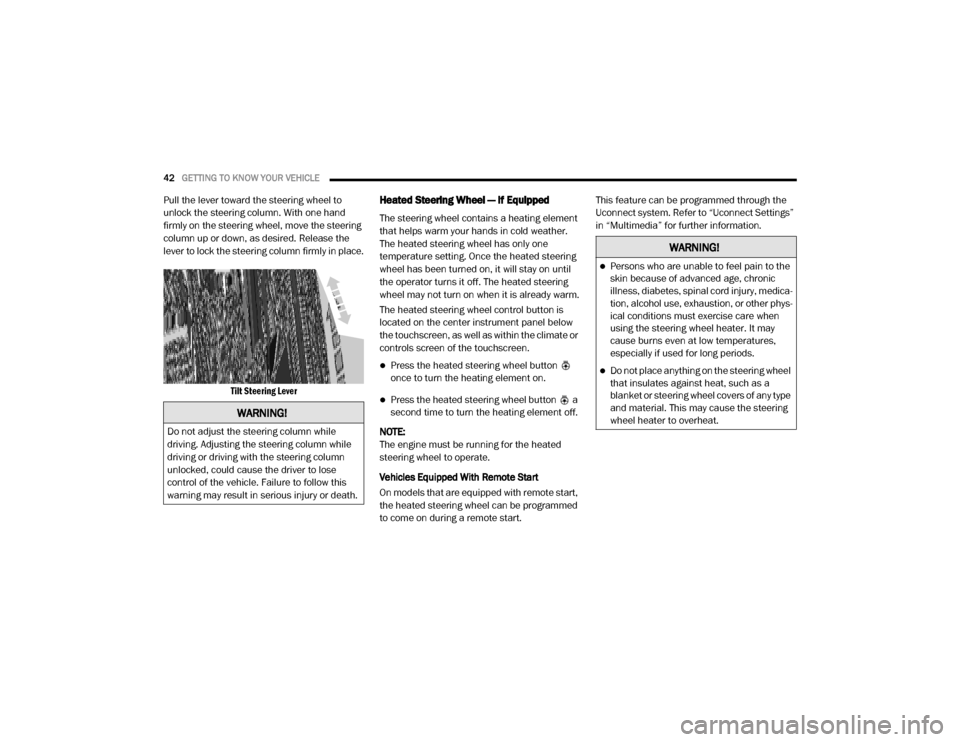
Pull the lever toward the steering wheel to
unlock the steering column. With one hand
firmly on the steering wheel, move the steering
column up or down, as desired. Release the
lever to lock the steering column firmly in place.
Tilt Steering Lever
Heated Steering Wheel — If Equipped
The steering wheel contains a heating element
that helps warm your hands in cold weather.
The heated steering wheel has only one
temperature setting. Once the heated steering
wheel has been turned on, it will stay on until
the operator turns it off. The heated steering
wheel may not turn on when it is already warm.
The heated steering wheel control button is
located on the center instrument panel below
the touchscreen, as well as within the climate or
controls screen of the touchscreen.
Press the heated steering wheel button
once to turn the heating element on.
Press the heated steering wheel button a
second time to turn the heating element off.
NOTE:
The engine must be running for the heated
steering wheel to operate.
Vehicles Equipped With Remote Start
On models that are equipped with remote start,
the heated steering wheel can be programmed
to come on during a remote start. This feature can be programmed through the
Uconnect system. Refer to “Uconnect Settings”
in “Multimedia” for further information.
WARNING!
Do not adjust the steering column while
driving. Adjusting the steering column while
driving or driving with the steering column
unlocked, could cause the driver to lose
control of the vehicle. Failure to follow this
warning may result in serious injury or death.
WARNING!
Persons who are unable to feel pain to the
skin because of advanced age, chronic
illness, diabetes, spinal cord injury, medica
-
tion, alcohol use, exhaustion, or other phys -
ical conditions must exercise care when
using the steering wheel heater. It may
cause burns even at low temperatures,
especially if used for long periods.
Do not place anything on the steering wheel
that insulates against heat, such as a
blanket or steering wheel covers of any type
and material. This may cause the steering
wheel heater to overheat.
20_DJD2_OM_EN_USC_t.book Page 42
Page 51 of 553
GETTING TO KNOW YOUR VEHICLE49
“Slide-On-Rod” Features Of Sun Visor — If
Equipped
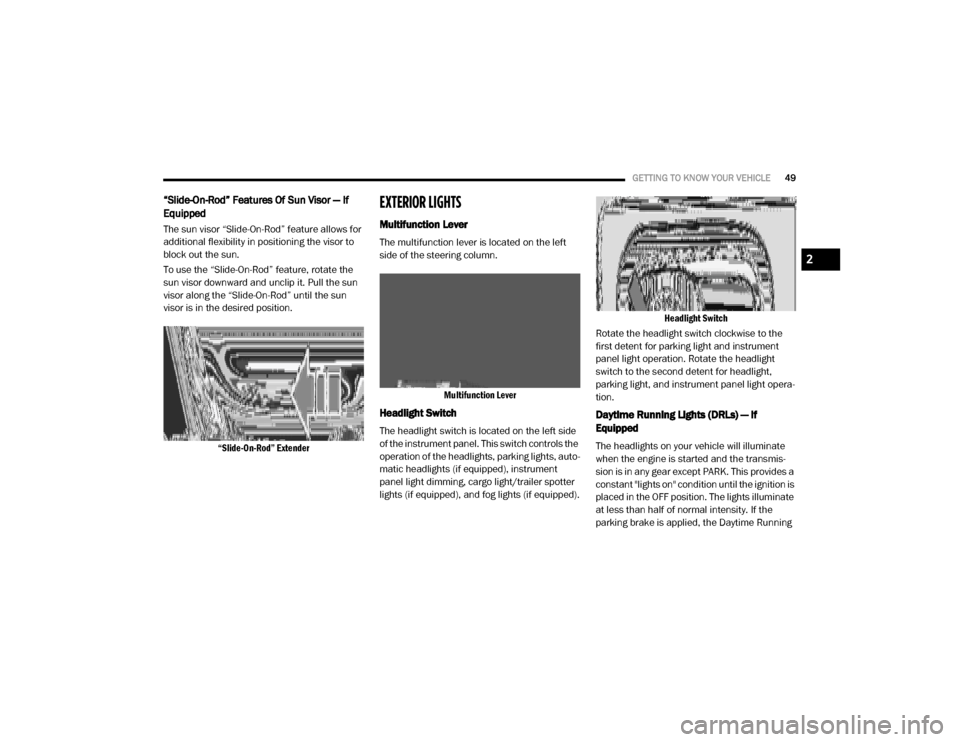
The sun visor “Slide-On-Rod” feature allows for
additional flexibility in positioning the visor to
block out the sun.
To use the “Slide-On-Rod” feature, rotate the
sun visor downward and unclip it. Pull the sun
visor along the “Slide-On-Rod” until the sun
visor is in the desired position.
“Slide-On-Rod” Extender
EXTERIOR LIGHTS
Multifunction Lever
The multifunction lever is located on the left
side of the steering column.
Multifunction Lever
Headlight Switch
The headlight switch is located on the left side
of the instrument panel. This switch controls the
operation of the headlights, parking lights, auto -
matic headlights (if equipped), instrument
panel light dimming, cargo light/trailer spotter
lights (if equipped), and fog lights (if equipped).
Headlight Switch
Rotate the headlight switch clockwise to the
first detent for parking light and instrument
panel light operation. Rotate the headlight
switch to the second detent for headlight,
parking light, and instrument panel light opera -
tion.
Daytime Running Lights (DRLs) — If
Equipped
The headlights on your vehicle will illuminate
when the engine is started and the transmis -
sion is in any gear except PARK. This provides a
constant "lights on" condition until the ignition is
placed in the OFF position. The lights illuminate
at less than half of normal intensity. If the
parking brake is applied, the Daytime Running
2
20_DJD2_OM_EN_USC_t.book Page 49