key Ram 2500 2020 Owner's Guide
[x] Cancel search | Manufacturer: RAM, Model Year: 2020, Model line: 2500, Model: Ram 2500 2020Pages: 553, PDF Size: 21.99 MB
Page 90 of 553
88GETTING TO KNOW YOUR VEHICLE
(Continued)
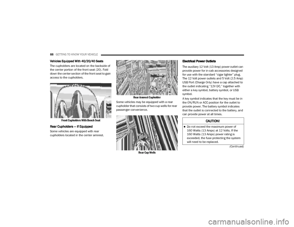
Vehicles Equipped With 40/20/40 Seats
The cupholders are located on the backside of
the center portion of the front seat (20). Fold
down the center section of the front seat to gain
access to the cupholders.
Front Cupholders With Bench Seat
Rear Cupholders — If Equipped
Some vehicles are equipped with rear
cupholders located in the center armrest.
Rear Armrest Cupholder
Some vehicles may be equipped with a rear
cupholder that consists of two cup wells for rear
passenger convenience.
Rear Cup Wells
Electrical Power Outlets
The auxiliary 12 Volt (13 Amp) power outlet can
provide power for in-cab accessories designed
for use with the standard “cigar lighter” plug.
The 12 Volt power outlets and 5 Volt (2.5 Amp)
USB Port (Charge Only) have a cap attached to
the outlet indicating “12V DC,” together with
either a key symbol, battery symbol, or USB
symbol.
A key symbol indicates that the key must be in
the ON/RUN or ACC position for the outlet to
provide power. The battery symbol indicates
that the outlet is connected to the battery, and
can provide power at all times.
CAUTION!
Do not exceed the maximum power of
160 Watts (13 Amps) at 12 Volts. If the
160 Watts (13 Amps) power rating is
exceeded, the fuse protecting the system
will need to be replaced.
20_DJD2_OM_EN_USC_t.book Page 88
Page 93 of 553
GETTING TO KNOW YOUR VEHICLE91
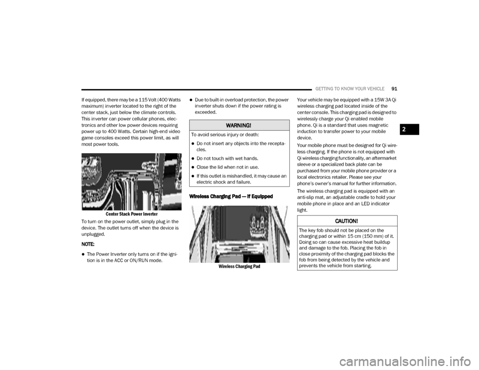
If equipped, there may be a 115 Volt (400 Watts
maximum) inverter located to the right of the
center stack, just below the climate controls.
This inverter can power cellular phones, elec -
tronics and other low power devices requiring
power up to 400 Watts. Certain high-end video
game consoles exceed this power limit, as will
most power tools.
Center Stack Power Inverter
To turn on the power outlet, simply plug in the
device. The outlet turns off when the device is
unplugged.
NOTE:
The Power Inverter only turns on if the igni -
tion is in the ACC or ON/RUN mode.
Due to built-in overload protection, the power
inverter shuts down if the power rating is
exceeded.
Wireless Charging Pad — If Equipped
Wireless Charging Pad
Your vehicle may be equipped with a 15W 3A Qi
wireless charging pad located inside of the
center console. This charging pad is designed to
wirelessly charge your Qi enabled mobile
phone. Qi is a standard that uses magnetic
induction to transfer power to your mobile
device.
Your mobile phone must be designed for Qi wire
-
less charging. If the phone is not equipped with
Qi wireless charging functionality, an aftermarket
sleeve or a specialized back plate can be
purchased from your mobile phone provider or a
local electronics retailer. Please see your
phone’s owner’s manual for further information.
The wireless charging pad is equipped with an
anti-slip mat, an adjustable cradle to hold your
mobile phone in place and an LED indicator
light.
WARNING!
To avoid serious injury or death:
Do not insert any objects into the recepta -
cles.
Do not touch with wet hands.
Close the lid when not in use.
If this outlet is mishandled, it may cause an
electric shock and failure.
CAUTION!
The key fob should not be placed on the
charging pad or within 15 cm (150 mm) of it.
Doing so can cause excessive heat buildup
and damage to the fob. Placing the fob in
close proximity of the charging pad blocks the
fob from being detected by the vehicle and
prevents the vehicle from starting.
2
20_DJD2_OM_EN_USC_t.book Page 91
Page 98 of 553

96GETTING TO KNOW YOUR VEHICLE
Locking And Unlocking RamBox
Push and release the lock or unlock button on
the key fob to lock and unlock all doors, the tail -
gate and the RamBox (if equipped). Refer to
“Keys” in this chapter for further details. The
RamBox storage bins can be locked using the
vehicle key. To lock and unlock the storage bin,
insert the key into the keyhole on the push
button and turn clockwise to lock or counter -
clockwise to unlock. Always return the key to the
upright (vertical) position before removing the
key from the push button.
RamBox Safety Warning
Carefully follow these warnings to help prevent
personal injury or damage to your vehicle:
RamBox Storage Bin Cover Emergency
Release Lever — If Equipped
As a security measure, a Storage Bin Cover
Emergency Release is built into the storage bin
cover latching mechanism.
Storage Bin Cover Emergency Release Lever
NOTE:
In the event of an individual being locked inside
the storage bin, the storage bin cover can be
opened from inside of the bin by pulling on the
glow-in-the-dark lever attached to the storage
bin cover latching mechanism.
Bed Divider — If Equipped
The bed divider has two functional positions:
Storage Position
Divider Position
CAUTION!
Ensure cargo bin lids are closed and
latched before moving or driving vehicle.
Loads applied to the top of the bin lid
should be minimized to prevent damage to
the lid and latching/hinging mechanisms.
Damage to the RamBox bin may occur due
to heavy/sharp objects placed in bin that
shift due to vehicle motion. In order to mini -
mize potential for damage, secure all cargo
to prevent movement and protect inside
surfaces of bin from heavy/sharp objects
with appropriate padding.
WARNING!
Always close the storage bin covers when
your vehicle is unattended.
Do not allow children to have access to the
storage bins. Once in the storage bin, young
children may not be able to escape. If
trapped in the storage bin, children can die
from suffocation or heat stroke.
In an accident, serious injury could result if
the storage bin covers are not properly
latched.
Do not drive the vehicle with the storage bin
covers open.
Keep the storage bin covers closed and
latched while the vehicle is in motion.
Do not use a storage bin latch as a tie
down.
20_DJD2_OM_EN_USC_t.book Page 96
Page 99 of 553
GETTING TO KNOW YOUR VEHICLE97
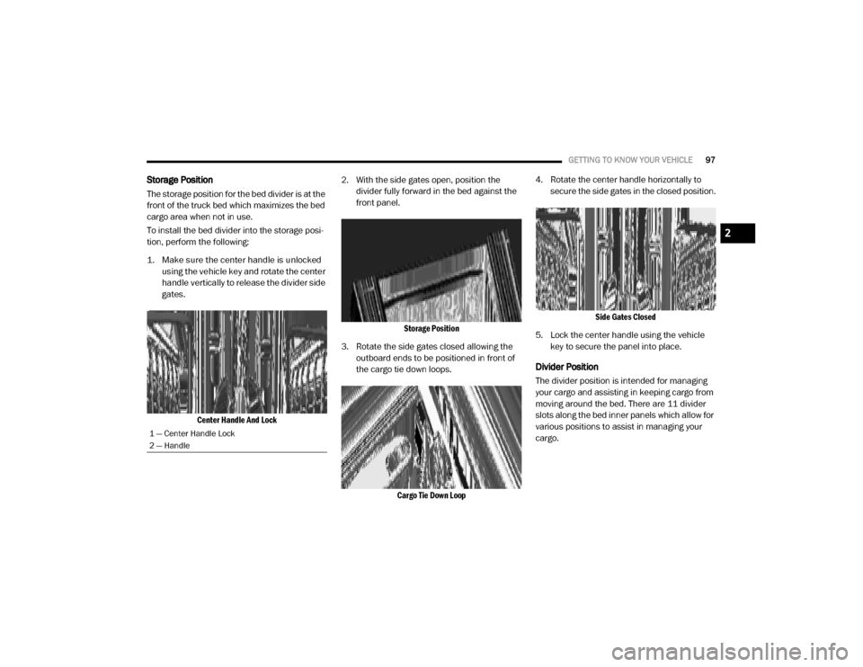
Storage Position
The storage position for the bed divider is at the
front of the truck bed which maximizes the bed
cargo area when not in use.
To install the bed divider into the storage posi -
tion, perform the following:
1. Make sure the center handle is unlocked using the vehicle key and rotate the center
handle vertically to release the divider side
gates.
Center Handle And Lock
2. With the side gates open, position the
divider fully forward in the bed against the
front panel.
Storage Position
3. Rotate the side gates closed allowing the outboard ends to be positioned in front of
the cargo tie down loops.
Cargo Tie Down Loop
4. Rotate the center handle horizontally to
secure the side gates in the closed position.
Side Gates Closed
5. Lock the center handle using the vehicle key to secure the panel into place.
Divider Position
The divider position is intended for managing
your cargo and assisting in keeping cargo from
moving around the bed. There are 11 divider
slots along the bed inner panels which allow for
various positions to assist in managing your
cargo.
1 — Center Handle Lock
2 — Handle
2
20_DJD2_OM_EN_USC_t.book Page 97
Page 100 of 553

98GETTING TO KNOW YOUR VEHICLE
To install the bed divider into a divider position,
perform the following:
1. Make sure the center handle is unlocked
using the vehicle key and rotate the center
handle vertically to release the divider side
gates.
Center Handle And Lock
2. With the side gates open, position the divider so the outboard ends align with the
intended slots in the sides of the bed.
Aligning Gate To Slots
3. Rotate the side gates closed so that the outboard ends are secured into the
intended slots of the bed.
4. Rotate the center handle horizontally to secure the side gates in the closed position.
Side Gates Closed
5. Lock the center handle to secure the panel
into place.
Bed Rail Tie-Down System — If Equipped
NOTE:
This feature is only available for vehicles
equipped with a RamBox.
There are two adjustable cleats on each side of the
bed that can be used to assist in securing cargo.
Adjustable Cleats
1 — Center Handle Lock
2 — Handle
CAUTION!
The maximum load per cleat should not
exceed 250 lbs (113 kg) and the angle of
the load on each cleat should not exceed
45 degrees above horizontal, or damage to
the cleat or cleat rail may occur.
20_DJD2_OM_EN_USC_t.book Page 98
Page 102 of 553

100GETTING TO KNOW YOUR VEHICLE
SLIDE-IN CAMPERS
Camper Applications
Certain truck models are not recommended for
slide-in campers. To determine if your vehicle is
excluded, please refer to the “Consumer Infor -
mation Truck-Camper Loading” document at
www.ramtrucks.com . For safety reasons, follow
all instructions in this important document.
NOTE:
When a cap or pickup camper is installed on a
vehicle, an alternate Center High-Mounted Stop
Light (CHMSL) must be provided.
EASY-OFF TAILGATE
To simplify mounting of a camper unit with an
overhang, the tailgate can be removed.
NOTE:
The electric connector at the bottom of the tail -
gate must be disconnected prior to removing
the tailgate.
Disconnecting The Rear Camera And
Remote Keyless Entry
1. Open the tailgate to access the rear camera or Remote Keyless Entry
connector bracket located on the rear sill.
Connector Bracket
2. Remove the connector bracket from the sill by pushing inward in the locking tab.
Locking Tab
3. Disconnect the chassis wiring harness, ensuring the connector bracket does not
fall into the sill.
4. Connect the chassis plug and bracket (provided in the glove compartment) to the
chassis wiring harness and insert the
bracket back into the sill.
5. Connect the tailgate plug (provided in the glove compartment) to the tailgate wiring
harness to ensure that the terminals do not
corrode.
6. Tape the tailgate harness and bracket against the forward-facing surface of the
tailgate. This will prevent damaging the
connector and bracket when storing or rein -
stalling the tailgate.
WARNING!
To avoid inhaling carbon monoxide, which is
deadly, the exhaust system on vehicles
equipped with “Cap or Slide-In Campers”
should extend beyond the overhanging
camper compartment and be free of leaks.
20_DJD2_OM_EN_USC_t.book Page 100
Page 103 of 553
GETTING TO KNOW YOUR VEHICLE101
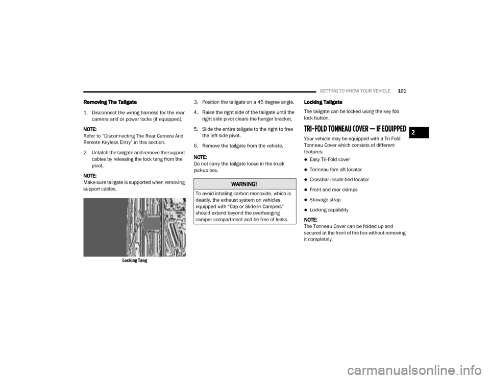
Removing The Tailgate
1. Disconnect the wiring harness for the rear
camera and or power locks (if equipped).
NOTE:
Refer to “Disconnecting The Rear Camera And
Remote Keyless Entry” in this section.
2. Unlatch the tailgate and remove the support cables by releasing the lock tang from the
pivot.
NOTE:
Make sure tailgate is supported when removing
support cables.
Locking Tang
3. Position the tailgate on a 45 degree angle.
4. Raise the right side of the tailgate until the
right side pivot clears the hanger bracket.
5. Slide the entire tailgate to the right to free the left side pivot.
6. Remove the tailgate from the vehicle.
NOTE:
Do not carry the tailgate loose in the truck
pickup box.
Locking Tailgate
The tailgate can be locked using the key fob
lock button.
TRI-FOLD TONNEAU COVER — IF EQUIPPED
Your vehicle may be equipped with a Tri-Fold
Tonneau Cover which consists of different
features:
Easy Tri-Fold cover
Tonneau fore aft locator
Crossbar inside bed locator
Front and rear clamps
Stowage strap
Locking capability
NOTE:
The Tonneau Cover can be folded up and
secured at the front of the box without removing
it completely.
WARNING!
To avoid inhaling carbon monoxide, which is
deadly, the exhaust system on vehicles
equipped with “Cap or Slide-In Campers”
should extend beyond the overhanging
camper compartment and be free of leaks.
2
20_DJD2_OM_EN_USC_t.book Page 101
Page 163 of 553
SAFETY161
When the system determines a collision with
the vehicle in front of you is no longer probable,
the warning message will be deactivated.
NOTE:
The minimum speed for FCW activation is
3 mph (5 km/h).
The FCW alerts may be triggered on objects
other than vehicles such as guard rails or
sign posts based on the course prediction.
This is expected and is a part of normal FCW
activation and functionality.
It is unsafe to test the FCW system. To
prevent such misuse of the system, after four
Active Braking events within a key cycle, the
Active Braking portion of FCW will be deacti -
vated until the next key cycle.
The FCW system is intended for on-road use
only. If the vehicle is taken off-road, the FCW
system should be deactivated to prevent
unnecessary warnings to the surroundings.
FCW may not react to irrelevant objects such
as overhead objects, ground reflections,
objects not in the path of the vehicle,
stationary objects that are far away, oncoming traffic, or leading vehicles with the
same or higher rate of speed.
“FCW will be disabled like ACC, with the
unavailable screens.
During a FCW event when towing a trailer,
your Electronic Brake system will respond, to
activate the trailer brakes (if equipped).
Turning FCW On or Off
The FCW button is located in the Uconnect
display in the control settings. Refer to “Ucon
-
nect Settings” in “Multimedia” in the Owner's
Manual for further information.
To turn the FCW system on, press the forward
collision button once.
To turn the FCW system off, press the forward
collision button once.
NOTE:
When the FCW is “on”, this allows the system
to warn the driver of a possible collision with
the vehicle in front.
When the FCW is “off” prevents the system
from warning the driver of a possible collision
with the vehicle in front. If the FCW is set to
“off”, “FCW OFF" will be displayed in the
instrument cluster display.
When FCW status is set to “Only Warning”
prevents the system from providing limited
active braking, or additional brake support if
the driver is not braking adequately in the
event of a potential frontal collision.
When FCW status is set to “Warning and
Braking” this allows the system to warn the
driver of a possible collision with the vehicle
in front using audible/visual warnings and it
applies autonomous braking.
The FCW system state is defaulted to “Full
On” from one ignition cycle to the next. If the
system is turned off, it will reset to “Full On”
when the vehicle is restarted.
WARNING!
Forward Collision Warning (FCW) is not
intended to avoid a collision on its own, nor
can FCW detect every type of potential
collision. The driver has the responsibility to
avoid a collision by controlling the vehicle via
braking and steering. Failure to follow this
warning could lead to serious injury or death.
4
20_DJD2_OM_EN_USC_t.book Page 161
Page 191 of 553

SAFETY189
(Continued)
Enhanced Accident Response System
In the event of an impact, if the communication
network remains intact, and the power remains
intact, depending on the nature of the event,
the Occupant Restraint Controller (ORC) will
determine whether to have the Enhanced Acci -
dent Response System perform the following
functions:
Cut off fuel to the engine (if equipped)
Cut off battery power to the electric motor (if
equipped)
Flash hazard lights as long as the battery has
power
Turn on the interior lights, which remain on
as long as the battery has power or for
15 minutes from the intervention of the
Enhanced Accident Response System
Unlock the power door locks
Your vehicle may also be designed to perform
any of these other functions in response to the
Enhanced Accident Response System:
Turn off the Fuel Filter Heater, Turn off the
HVAC Blower Motor, Close the HVAC Circula -
tion Door
Cut off battery power to the:
Engine
Electric Motor (if equipped)
Electric power steering
Brake booster
Electric park brake
Automatic transmission gear selector
Horn
Front wiper
Headlamp washer pump
NOTE:
After an accident, remember to cycle the ignition
to the STOP (OFF/LOCK) position and remove the
key from the ignition switch to avoid draining the
battery. Carefully check the vehicle for fuel leaks
in the engine compartment and on the ground
near the engine compartment and fuel tank
before resetting the system and starting the
engine. If there are no fuel leaks or damage to the
vehicle electrical devices (e.g. headlights) after an
accident, reset the system by following the proce -
dure described below. If you have any doubt,
contact an authorized dealer.
Enhanced Accident Response System Reset
Procedure
In order to reset the Enhanced Accident
Response System functions after an event, the
ignition switch must be changed from ignition
START or ON/RUN to ignition OFF. Carefully
check the vehicle for fuel leaks in the engine
compartment and on the ground near the
engine compartment and fuel tank before reset -
ting the system and starting the engine.
Maintaining Your Air Bag System
WARNING!
Modifications to any part of the air bag
system could cause it to fail when you need
it. You could be injured if the air bag system
is not there to protect you. Do not modify
the components or wiring, including adding
any kind of badges or stickers to the
steering wheel hub trim cover or the upper
passenger side of the instrument panel. Do
not modify the front bumper, vehicle body
structure, or add aftermarket side steps or
running boards.
4
20_DJD2_OM_EN_USC_t.book Page 189
Page 212 of 553
210SAFETY
(Continued)
Periodic Safety Checks You Should Make
Outside The Vehicle
Tires
Examine tires for excessive tread wear and
uneven wear patterns. Check for stones, nails,
glass, or other objects lodged in the tread or
sidewall. Inspect the tread for cuts and cracks.
Inspect sidewalls for cuts, cracks, and bulges.
Check the wheel bolts for tightness. Check the
tires (including spare) for proper cold inflation
pressure.
Lights
Have someone observe the operation of brake
lights and exterior lights while you work the
controls. Check turn signal and high beam indi -
cator lights on the instrument panel.
Door Latches
Check for proper closing, latching, and locking.
Fluid Leaks
Check area under the vehicle after overnight
parking for fuel, coolant, oil, or other fluid leaks.
Also, if gasoline fumes are detected or if fuel, or
brake fluid leaks are suspected, the cause
should be located and corrected immediately.
ONLY install floor mats designed to fit your
vehicle. NEVER install a floor mat that
cannot be properly attached and secured to
your vehicle. If a floor mat needs to be
replaced, only use a FCA approved floor
mat for the specific make, model, and year
of your vehicle.
ONLY use the driver’s side floor mat on the
driver’s side floor area. To check for inter -
ference, with the vehicle properly parked
with the engine off, fully depress the accel-
erator, the brake, and the clutch pedal (if
present) to check for interference. If your
floor mat interferes with the operation of
any pedal, or is not secure to the floor,
remove the floor mat from the vehicle and
place the floor mat in your trunk.
ONLY use the passenger’s side floor mat on
the passenger’s side floor area.
WARNING! (Continued)
ALWAYS make sure objects cannot fall or
slide into the driver’s side floor area when
the vehicle is moving. Objects can become
trapped under accelerator, brake, or clutch
pedals and could cause a loss of vehicle
control.
NEVER place any objects under the floor
mat (e.g., towels, keys, etc.). These objects
could change the position of the floor mat
and may cause interference with the accel -
erator, brake, or clutch pedals.
If the vehicle carpet has been removed and
re-installed, always properly attach carpet
to the floor and check the floor mat
fasteners are secure to the vehicle carpet.
Fully depress each pedal to check for inter -
ference with the accelerator, brake, or
clutch pedals then re-install the floor mats.
It is recommended to only use mild soap
and water to clean your floor mats. After
cleaning, always check your floor mat has
been properly installed and is secured to
your vehicle using the floor mat fasteners
by lightly pulling mat.
WARNING! (Continued)
20_DJD2_OM_EN_USC_t.book Page 210