steering Ram 2500 2020 Service Manual
[x] Cancel search | Manufacturer: RAM, Model Year: 2020, Model line: 2500, Model: Ram 2500 2020Pages: 553, PDF Size: 21.99 MB
Page 264 of 553

262STARTING AND OPERATING
hung up on something you should jack the
vehicle up and stack something under the
wheels to allow the vehicle to roll off the object
without causing further damage. This should be
tried before attempting any recovery method.
Rock Cycling Your Vehicle – Rock cycling your
vehicle is one of the easiest, fastest and
most commonly used methods. This simply
involves shifting your vehicle from DRIVE to
REVERSE, while applying throttle after each
shift. During this process, for additional trac -
tion, try turning your steering wheel quickly
left and right no more than a quarter turn. If
you are stuck in mud, sand, or snow try spin -
ning your tires during this process to clean
the debris from the tread and improve the
traction. You want to create a rocking motion
with the vehicle. This helps build vehicle
momentum, which hopefully gets you out.
Remember to ease off and on the accelerator before and after the shift. If after a few rock
cycles your vehicle is not free, stop and try
another method of recovery. Continuous rock
cycling will only cause unnecessary damage
to your vehicle and the environment.
Using The Tow Hooks With A Tow Strap
– Tow
straps are a quick and easy way to recover
your vehicle from minor situations if you have
a secondary vehicle which is not stuck. The
tow hooks on your vehicle are designed to
take the abusive force generated during
vehicle recovery. Do not use the bumper or
any other vehicle component as an attach -
ment point. Using tow straps requires coordi -
nation between the two drivers. Good
communication and line of sight are required
for a safe recovery. First connect the tow
strap to the correct attachment points on both vehicles. There should be a least 20 to
30 feet (6 to 9 meters) between the vehicles
to allow for a safe recovery. If necessary join
two tow straps together using a 1.5 inch hard
wood dowel. This will keep the straps from
becoming knotted and is safer than using a
clevis pin if the strap breaks. Next have the
tow vehicle backup, leaving two to three feet
worth of slack in the strap. Then the tow
vehicle, using light throttle, should accelerate
tightening the strap providing the pulling
force needed to free the vehicle. The vehicle
being recovered should assist in the
recovery, at the time of the snap, by slowly
spinning the tires in the same direction as
the pulling vehicle. After the vehicle becomes
free, the driver of the previously stuck vehicle
should signal they are free and should hit
their brakes stopping both vehicles. The
driver of the pulling vehicle should let off the
throttle without using the brakes, once
signaled by the other driver. This sequence is
important to avoid having the recovered
vehicle hit the pulling vehicle.
CAUTION!
Pulling the vehicle off an obstacle, without
first clearing the object, may result in
additional underbody damage.
CAUTION!
Damage can occur when spinning your tires
at an excessive high speed. Do not spin your
tires faster than an indicated 30 mph
(48 km/h).
20_DJD2_OM_EN_USC_t.book Page 262
Page 265 of 553

STARTING AND OPERATING263
Winching (Refer To “Winch Operation” For
Additional Information) – Winching is most
commonly used in the following situations:
there is no support vehicle available, a high
controlled force is required to recover the
vehicle, there is a high risk of environmental
or vehicle damage, or where nothing else
seems to work. A winch can deliver a high
pulling force with a great deal of control. It
allows you to walk the vehicle out of the situ -
ation in a slow controlled manner. This
control works well for avoiding further vehicle
damage. Once you decide it is time to use the
winch look for a good anchor point. It needs
to be strong enough to hold more than the vehicle's weight and provide a direction of
pull as straight as possible. Use block and
tackle if necessary to improve the angle of
pull or increase the winch's pulling force. If
the anchor point is a tree use a strap around
its base and hook the cable to the strap. If it
is another vehicle, then place that vehicle in
PARK and block the front tires. If you cannot
find an anchor point within reach try using
your spare tire by burying it. Once you have
determined an anchor point hook up the
cable, ensuring there are a least five wraps of
cable left on the drum, and place a floor mat
or something else over the strung out cable.
Placing something over the strung out cable
helps keep the cable on the ground if it
breaks. Next, place the vehicle in FIRST gear
and apply a very light throttle as you power
the winch in. Be careful not to allow slack in
the cable as you recover the vehicle. Do not
try to guide the cable into the drum. If it starts
to bunch up on one end, let it. You can
re-spool the cable afterwards. Never use a
winch cable as a tow strap and always stand
back while winching.
After Driving Off-Road
Off-road operation puts more stress on your
vehicle than does most on-road driving. After
going off-road, it is always a good idea to check
for damage. That way you can get any problems
taken care of right away and have your vehicle
ready when you need it.
Completely inspect the underbody of your
vehicle. Check tires, body structure, steering,
suspension, and exhaust system for damage.
Inspect the radiator for mud and debris and
clean as required.
WARNING!
Never use tow straps with end hooks or link
two straps with a clevis pin. These heavy
metal objects could become projectiles if a
strap breaks, which could cause severe
injury. Never leave more than 2 to 3 feet
(0.60 to 1 meter) of slack in the strap. More
slack than this greatly increases the risk of
injury and vehicle damage. Always keep
everyone at least 30 feet (9 meters) away
from a strapping or winching situation.
WARNING!
Winch cables are under high tension when in
use and can become a projectile if they fail.
Never stand over or straddle the winch cable.
Never jerk or overload the winch cable. Never
stand in front of the vehicle while winching.
Failure to follow these instructions can result
in serious or fatal injury.
5
20_DJD2_OM_EN_USC_t.book Page 263
Page 266 of 553
264STARTING AND OPERATING
Check threaded fasteners for looseness,
particularly on the chassis, drivetrain compo -
nents, steering, and suspension. Retighten
them, if required, and torque to the values
specified in the Service Manual.
Check for accumulations of plants or brush.
These things could be a fire hazard. They
might hide damage to fuel lines, brake hoses,
axle pinion seals, and propeller shafts.
After extended operation in mud, sand,
water, or similar dirty conditions, have the
radiator, fan, brake rotors, wheels, brake
linings, and axle yokes inspected and
cleaned as soon as possible.
If you experience unusual vibration after
driving in mud, slush or similar conditions,
check the wheels for impacted material.
Impacted material can cause a wheel imbal-
ance and freeing the wheels of it will correct
the situation.
LIMITED-SLIP DIFFERENTIAL
The limited-slip differential provides additional
traction on snow, ice, mud, sand and gravel,
particularly when there is a difference between
the traction characteristics of the surface under
the right and left rear wheels. During normal
driving and cornering, the limited-slip unit
performs similarly to a conventional differential.
On slippery surfaces, however, the differential
delivers more of the driving effort to the rear
wheel having the better traction.
The limited-slip differential is especially helpful
during slippery driving conditions. With both
rear wheels on a slippery surface, a slight appli -
cation of the accelerator will supply maximum
traction. When starting with only one rear wheel
on an excessively slippery surface, slight
momentary application of the parking brake
may be necessary to gain maximum traction. Care should be taken to avoid sudden accelera-
tions when both rear wheels are on a slippery
surface. This could cause both rear wheels to
spin, and allow the vehicle to slide sideways on
the crowned surface of a road or in a turn.
WINCH USAGE — POWER WAGON ONLY (IF
EQUIPPED)
Things To Know Before Using Your Winch
General Winch Information
Your vehicle is equipped with an electric vehicle
recovery winch. This winch uses the electrical
power from the vehicle charging system to
power a motor that winds the winch rope onto
the winch drum via planetary gear reduction. By
nature, a winch is capable of generating very
high forces and should be used with care. Do
WARNING!
Abrasive material in any part of the brakes
may cause excessive wear or unpredictable
braking. You might not have full braking
power when you need it to prevent a collision.
If you have been operating your vehicle in
dirty conditions, get your brakes checked and
cleaned as necessary.
WARNING!
On vehicles equipped with a limited-slip
differential never run the engine with one rear
wheel off the ground since the vehicle may
drive through the rear wheel remaining on the
ground. You could lose control of the vehicle.
20_DJD2_OM_EN_USC_t.book Page 264
Page 275 of 553
STARTING AND OPERATING273
Increasing Pulling Power
In some cases, you may find yourself needing
more pulling power. The use of snatch blocks
increases mechanical advantage and that
increases your pulling power.
Double Line
Wire Rope Routing
Because pulling power decreases with the
number of layers of synthetic rope on the winch
drum, you can use a snatch block to double line
out more rope. This decreases the number of
layers of synthetic rope on the drum, and
increases pulling power. Start by feeding out
enough synthetic rope to free the winch hook.
Attach the hook to your vehicle's frame/tow
hook and run the rope through a snatch block.
Disengage the clutch and, using the snatch block, pull out enough synthetic rope to reach
your anchor point. Do not attach the hook to the
mounting kit. Secure to the anchor point with a
tree trunk protector or choker chain. Attach the
clevis/shackle. Attach the shackle to the two
ends of the strap/chain, being careful not to
over tighten (tighten and back-off 1/2 turn).
FUEL SAVER TECHNOLOGY — GAS ENGINE
(IF EQUIPPED)
This feature offers improved fuel economy by
shutting off four of the engine's eight cylinders
during light load and cruise conditions. The
system is automatic with no driver inputs or
additional driving skills required.
NOTE:
This system may take some time to return to full
functionality after a battery disconnect.
SPEED CONTROL
When engaged, the Speed Control takes over
accelerator operations at speeds greater than
20 mph (32 km/h), or 25 mph (40 km/h),
depending on the powertrain used.
The Speed Control buttons are located on the
right side of the steering wheel.
Speed Control Buttons
NOTE:
In order to ensure proper operation, the Speed
Control system has been designed to shut down
if multiple speed control functions are operated
at the same time. If this occurs, the Speed
Control system can be reactivated by pushing
the Speed Control on/off button and resetting
the desired vehicle set speed.
1 — On/Off Button
2 — RES (+)
3 — SET (-)
4 — CANCEL
5
20_DJD2_OM_EN_USC_t.book Page 273
Page 278 of 553
276STARTING AND OPERATING
(Continued)
(Continued)
NOTE:
If the sensor does not detect a vehicle ahead
of you, ACC will maintain a fixed set speed.
If the ACC sensor detects a vehicle ahead,
ACC will apply limited braking or accelerate
(not to exceed the original set speed) auto -
matically to maintain a preset following
distance, while matching the speed of the
vehicle ahead.
The Cruise Control system has two control
modes:
Adaptive Cruise Control mode for main -
taining an appropriate distance between
vehicles.
Normal (Fixed Speed) Cruise Control mode
for cruising at a constant preset speed. For
additional information, refer to “Normal
(Fixed Speed) Cruise Control Mode” in this
section.
NOTE:
Normal (Fixed Speed) Cruise Control will not
react to preceding vehicles. Always be aware of
the mode selected. You can change the mode by using the Cruise
Control buttons. The two control modes func
-
tion differently. Always confirm which mode is
selected.
WARNING!
Adaptive Cruise Control (ACC) is a conve -
nience system. It is not a substitute for
active driving involvement. It is always the
driver’s responsibility to be attentive of
road, traffic, and weather conditions,
vehicle speed, distance to the vehicle
ahead; and, most importantly, brake opera -
tion to ensure safe operation of the vehicle
under all road conditions. Your complete
attention is always required while driving to
maintain safe control of your vehicle.
Failure to follow these warnings can result
in a collision and death or serious personal
injury.
The ACC system:
Does not react to pedestrians,
oncoming vehicles, and stationary
objects (e.g., a stopped vehicle in a
traffic jam or a disabled vehicle).
Cannot take street, traffic, and weather conditions into account, and may be
limited upon adverse sight distance
conditions.
Does not always fully recognize complex driving conditions, which can
result in wrong or missing distance
warnings.
Will bring the vehicle to a complete stop while following a target vehicle and hold
the vehicle for approximately two
seconds in the stop position. At this
point, there will be an “ACC may cancel
soon” chime and warning to the driver.
When ACC is cancelled, the system will
release the brakes and the driver must
take over braking. The system can be
resumed when the target vehicle drives
off by releasing the brake and pushing
the resume button on the steering
wheel.
WARNING! (Continued)
20_DJD2_OM_EN_USC_t.book Page 276
Page 279 of 553
STARTING AND OPERATING277
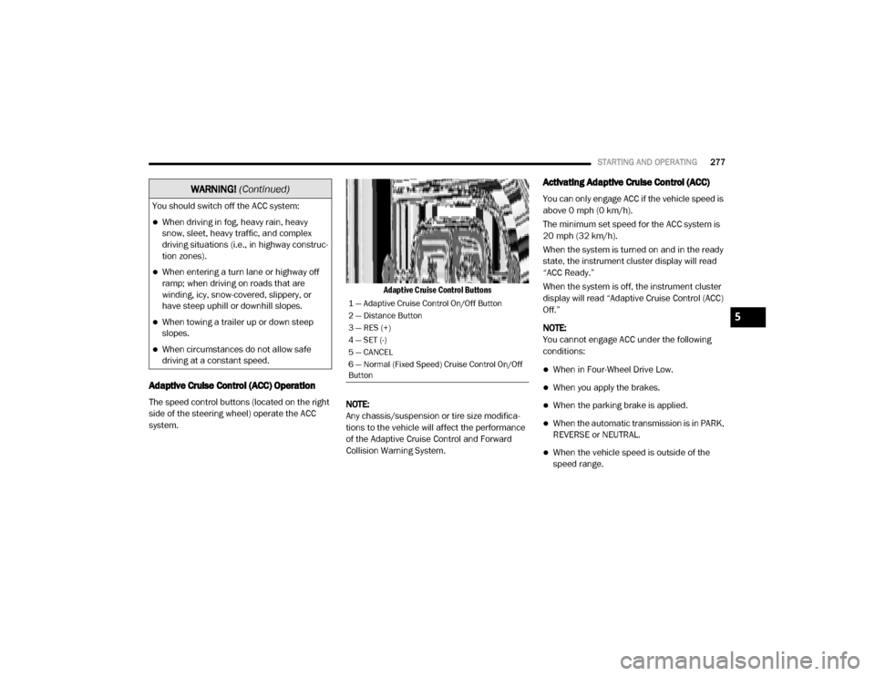
Adaptive Cruise Control (ACC) Operation
The speed control buttons (located on the right
side of the steering wheel) operate the ACC
system.
Adaptive Cruise Control Buttons
NOTE:
Any chassis/suspension or tire size modifica -
tions to the vehicle will affect the performance
of the Adaptive Cruise Control and Forward
Collision Warning System.
Activating Adaptive Cruise Control (ACC)
You can only engage ACC if the vehicle speed is
above 0 mph (0 km/h).
The minimum set speed for the ACC system is
20 mph (32 km/h).
When the system is turned on and in the ready
state, the instrument cluster display will read
“ACC Ready.”
When the system is off, the instrument cluster
display will read “Adaptive Cruise Control (ACC)
Off.”
NOTE:
You cannot engage ACC under the following
conditions:
When in Four-Wheel Drive Low.
When you apply the brakes.
When the parking brake is applied.
When the automatic transmission is in PARK,
REVERSE or NEUTRAL.
When the vehicle speed is outside of the
speed range.
You should switch off the ACC system:
When driving in fog, heavy rain, heavy
snow, sleet, heavy traffic, and complex
driving situations (i.e., in highway construc
-
tion zones).
When entering a turn lane or highway off
ramp; when driving on roads that are
winding, icy, snow-covered, slippery, or
have steep uphill or downhill slopes.
When towing a trailer up or down steep
slopes.
When circumstances do not allow safe
driving at a constant speed.
WARNING! (Continued)
1 — Adaptive Cruise Control On/Off Button
2 — Distance Button
3 — RES (+)
4 — SET (-)
5 — CANCEL
6 — Normal (Fixed Speed) Cruise Control On/Off
Button
5
20_DJD2_OM_EN_USC_t.book Page 277
Page 284 of 553
282STARTING AND OPERATING
NOTE:
The brake lights will illuminate whenever the
ACC system applies the brakes.
A Proximity Warning will alert the driver if ACC
predicts that its maximum braking level is not
sufficient to maintain the set distance. If this
occurs, a visual alert “BRAKE” will flash in the
instrument cluster display and a chime will
sound while ACC continues to apply its
maximum braking capacity.
Brake Alert
NOTE:
The “BRAKE!” Screen in the instrument cluster
display is a warning for the driver to take action
and does not necessarily mean that the
Forward Collision Warning system is applying
the brakes autonomously. Trailer Detect — If Equipped
When a trailer is detected, the ACC system auto
-
matically defaults to the longest setting (four
bars). The setting can be overridden by pushing
the Distance Button on the steering wheel.
Overtake Aid
When driving with ACC engaged and following a
vehicle, the system will provide an additional
acceleration up to the ACC set speed to assist in
passing the vehicle. This additional acceleration
is triggered when the driver utilizes the left turn
signal and will only be active when passing on
the left hand side.
ACC Operation At Stop
In the event that the ACC system brings your
vehicle to a standstill while following a target
vehicle, if the target vehicle starts moving within
two seconds of your vehicle coming to a stand -
still, your vehicle will resume motion without the
need for any driver action.
If the target vehicle does not start moving within
two seconds of your vehicle coming to a stand -
still, then ACC will cancel and the driver must
take over braking. When the target vehicle
drives off, ACC can be resumed by releasing the
brake and pushing the RES (+) button. NOTE:
After the ACC system holds your vehicle at a
standstill for approximately two seconds, a chime
will sound and an “ACC may cancel soon” warning
will display. The brakes will release when ACC is
canceled and the driver must take over braking.
While ACC is holding your vehicle at a standstill, if
the driver seatbelt is unbuckled or the driver door
is opened, the ACC system will cancel and the
brakes will release. Driver intervention will be
required at this mo ment.
Adaptive Cruise Control (ACC) Menu
The instrument cluster display will show the
current ACC system settings. The instrument
cluster display is located in the center of the
instrument cluster. The information it displays
depends on ACC system status.
WARNING!
When the ACC system is resumed, the driver
must ensure that there are no pedestrians,
vehicles or objects in the path of the vehicle.
Failure to follow these warnings can result in
a collision and death or serious personal
injury.
20_DJD2_OM_EN_USC_t.book Page 282
Page 285 of 553

STARTING AND OPERATING283
Push the Adaptive Cruise Control (ACC) on/off
button (located on the steering wheel) until one
of the following appears in the instrument
cluster display:
Adaptive Cruise Control Off
When ACC is deactivated, the display will read
“Adaptive Cruise Control Off.”
Adaptive Cruise Control Ready
When ACC is activated, but the vehicle speed
setting has not been selected, the display will
read “Adaptive Cruise Control Ready.”
Adaptive Cruise Control Set
When the RES (+) or the SET(-) button (located
on the steering wheel) is pushed, the display will
read “ACC SET.”
When ACC is set, the set speed will show in the
instrument cluster display.
The ACC screen may display once again if any
ACC activity occurs, which may include any of
the following:
System Cancel
Driver Override
System Off
ACC Proximity Warning
ACC Unavailable Warning
The instrument cluster display will return to
the last display selected after five seconds of
no ACC display activity
Display Warnings And Maintenance
“Wipe Front Radar Sensor In Front Of
Vehicle” Warning
The “ACC/FCW Unavailable Wipe Front Radar
Sensor” warning will display and also a chime
will indicate when conditions temporarily limit
system performance.
This most often occurs at times of poor visibility,
such as in snow or heavy rain. The ACC system
may also become temporarily blinded due to
obstructions, such as mud, dirt or ice. In these
cases, the instrument cluster display will display
“ACC/FCW Unavailable Wipe Front Radar
Sensor” and the system will deactivate.
The “ACC/FCW Unavailable Wipe Front Radar
Sensor” message can sometimes be displayed
while driving in highly reflective areas (i.e.
tunnels with reflective tiles, or ice and snow).
The ACC system will recover after the vehicle has left these areas. Under rare conditions,
when the radar is not tracking any vehicles or
objects in its path this warning may temporarily
occur.
NOTE:
If the “ACC/FCW Unavailable Wipe Front Radar
Sensor” warning is active Normal (Fixed Speed)
Cruise Control is still available. For additional
information refer to “Normal (Fixed Speed)
Cruise Control Mode” in this section.
If weather conditions are not a factor, the driver
should examine the sensor. It may require
cleaning or removal of an obstruction. The
sensor is located in the camera in the center of
the windshield, on the forward side of the rear
-
view mirror.
To keep the ACC System operating properly, it is
important to note the following maintenance
items:
Always keep the sensor clean. Carefully clear
the windshield.
Do not remove any screws from the sensor.
Doing so could cause an ACC system
5
20_DJD2_OM_EN_USC_t.book Page 283
Page 301 of 553

STARTING AND OPERATING299
LANESENSE — IF EQUIPPED
LaneSense Operation
The LaneSense system is operational at speeds
above 37 mph (60 km/h) and below 112 mph
(180 km/h). It uses a forward looking camera to
detect lane markings and measure vehicle posi -
tion within the lane boundaries.
When both lane markings are detected and the
driver unintentionally drifts out of the lane while
no turn signal has been applied OR the driver
departs the lane on the opposite side of the
applied turn signal (if the left turn signal is applied and the vehicle departs to the right), the
LaneSense system provides a haptic warning in
the form of torque applied to the steering wheel
to prompt the driver to remain within the lane
boundaries. The LaneSense system will also
provide a visual warning through the instrument
cluster display to prompt the driver to remain
within the lane boundaries.
The driver may manually override the haptic
warning by applying torque into the steering
wheel at any time.
When only a single lane marking is detected
and the driver unintentionally drifts across that
lane marking (no turn signal applied), the Lane
-
Sense system provides a visual warning
through the instrument cluster display to
prompt the driver to remain within the lane.
When only a single lane marking is detected, a
haptic (torque) warning will not be provided.
NOTE:
When operating conditions have been met, the
LaneSense system will monitor if the driver’s
hands are on the steering wheel and provides
an audible and visual warning to the driver
when the driver’s hands are not detected on the
steering wheel. The system will cancel if the
driver does not return their hands to the wheel.
WARNING!
Drivers must be careful when backing up
even when using ParkSense. Always check
carefully behind your vehicle, look behind
you, and be sure to check for pedestrians,
animals, other vehicles, obstructions, and
blind spots before backing up. You are
responsible for safety and must continue to
pay attention to your surroundings. Failure
to do so can result in serious injury or
death.
Before using ParkSense, it is strongly
recommended that the ball mount and
hitch ball assembly is disconnected from
the vehicle when the vehicle is not used for
towing. Failure to do so can result in injury
or damage to vehicles or obstacles
because the hitch ball will be much closer
to the obstacle than the rear fascia when
the loudspeaker sounds the continuous
tone. Also, the sensors could detect the ball
mount and hitch ball assembly, depending
on its size and shape, giving a false indica -
tion that an obstacle is behind the vehicle.
CAUTION!
ParkSense is only a parking aid and it is
unable to recognize every obstacle,
including small obstacles. Parking curbs
might be temporarily detected or not
detected at all. Obstacles located above or
below the sensors will not be detected
when they are in close proximity.
The vehicle must be driven slowly when
using ParkSense in order to be able to stop
in time when an obstacle is detected. It is
recommended that the driver looks over
his/her shoulder when using ParkSense.
5
20_DJD2_OM_EN_USC_t.book Page 299
Page 303 of 553
STARTING AND OPERATING301
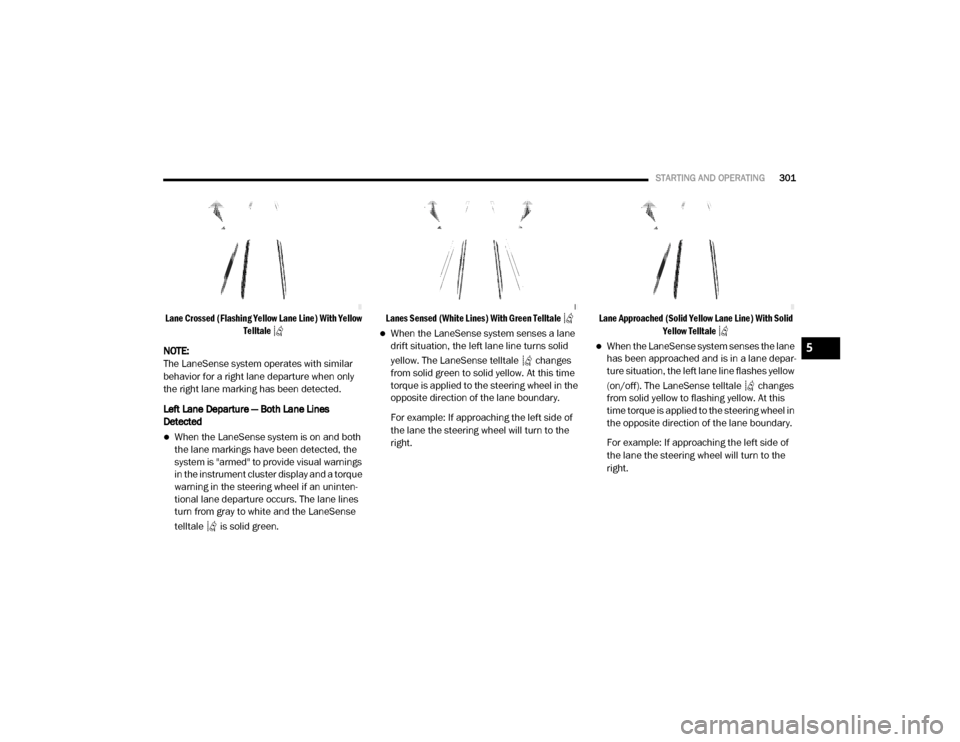
Lane Crossed (Flashing Yellow Lane Line) With Yellow
Telltale
NOTE:
The LaneSense system operates with similar
behavior for a right lane departure when only
the right lane marking has been detected.
Left Lane Departure — Both Lane Lines
Detected
When the LaneSense system is on and both
the lane markings have been detected, the
system is "armed" to provide visual warnings
in the instrument cluster display and a torque
warning in the steering wheel if an uninten -
tional lane departure occurs. The lane lines
turn from gray to white and the LaneSense
telltale is solid green.
Lanes Sensed (White Lines) With Green Telltale
When the LaneSense system senses a lane
drift situation, the left lane line turns solid
yellow. The LaneSense telltale changes
from solid green to solid yellow. At this time
torque is applied to the steering wheel in the
opposite direction of the lane boundary.
For example: If approaching the left side of
the lane the steering wheel will turn to the
right.
Lane Approached (Solid Yellow Lane Line) With Solid
Yellow Telltale
When the LaneSense system senses the lane
has been approached and is in a lane depar -
ture situation, the left lane line flashes yellow
(on/off). The LaneSense telltale changes
from solid yellow to flashing yellow. At this
time torque is applied to the steering wheel in
the opposite direction of the lane boundary.
For example: If approaching the left side of
the lane the steering wheel will turn to the
right.5
20_DJD2_OM_EN_USC_t.book Page 301