steering Ram 2500 2020 Workshop Manual
[x] Cancel search | Manufacturer: RAM, Model Year: 2020, Model line: 2500, Model: Ram 2500 2020Pages: 553, PDF Size: 21.99 MB
Page 304 of 553
302STARTING AND OPERATING
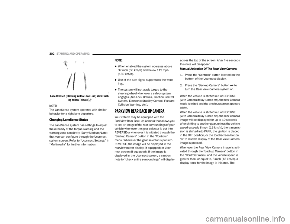
Lane Crossed (Flashing Yellow Lane Line) With Flash -
ing Yellow Telltale
NOTE:
The LaneSense system operates with similar
behavior for a right lane departure.
Changing LaneSense Status
The LaneSense system has settings to adjust
the intensity of the torque warning and the
warning zone sensitivity (Early/Medium/Late)
that you can configure through the Uconnect
system screen. Refer to “Uconnect Settings” in
“Multimedia” for further information. NOTE:
When enabled the system operates above
37 mph (60 km/h) and below 112 mph
(180 km/h).
Use of the turn signal suppresses the warn
-
ings.
The system will not apply torque to the
steering wheel whenever a safety system
engages (Anti-Lock Brakes, Traction Control
System, Electronic Stability Control, Forward
Collision Warning, etc.).
PARKVIEW REAR BACK UP CAMERA
Your vehicle may be equipped with the
ParkView Rear Back Up Camera that allows you
to see an image of the rear surroundings of your
vehicle whenever the gear selector is put into
REVERSE or whenever it is initiated through the
"Backup Camera" button in the "Controls"
menu. Whenever the gear selector is put into
REVERSE, the image will be displayed in the
rearview mirror display (if equipped) or Ucon -
nect screen (if equipped). If the image is
displayed in the Uconnect screen, a caution
note to “check entire surroundings” will display across the top of the screen. After five seconds
this note will disappear.
Manual Activation Of The Rear View Camera:
1. Press the "Controls" button located on the
bottom of the Uconnect display.
2. Press the "Backup Camera" button to turn the Rear View Camera system on.
When the vehicle is shifted out of REVERSE
(with Camera delay turned off), the rear Camera
mode is exited and the previous screen appears
again.
When the vehicle is shifted out of REVERSE
(with Camera delay turned on), the rear Camera
image will be displayed for up to 10 seconds
after shifting to another gear, unless the vehicle
speed exceeds 8 mph (13 km/h), the transmis- sion is shifted into PARK, the ignition is placed
in the OFF position, or the touchscreen button
“X” to disable display of the Rear View Camera
image is pressed.
Whenever the Rear View Camera image is acti -
vated through the "Backup Camera" button in
the "Controls" menu, and the vehicle speed is
greater than, or equal to, 8 mph (13 km/h), a display timer for the image is initiated. The
20_DJD2_OM_EN_USC_t.book Page 302
Page 305 of 553
STARTING AND OPERATING303
image will continue to be displayed until the
display timer exceeds 10 seconds.
NOTE:
If the vehicle speed remains below 8 mph
(13 km/h), the Rear View Camera image will
be displayed continuously until deactivated
via the touchscreen button "X", the transmis -
sion is shifted into PARK, or the ignition is
placed in the OFF position.
The touchscreen button "X" to disable display
of the camera image is made available ONLY
when the vehicle is not in REVERSE.
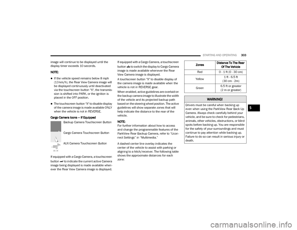
Cargo Camera Icons — If Equipped Backup Camera Touchscreen Button
Cargo Camera Touchscreen Button
AUX Camera Touchscreen Button
If equipped with a Cargo Camera, a touchscreen
button to indicate the current active Camera
image being displayed is made available when -
ever the Rear View Camera image is displayed. If equipped with a Cargo Camera, a touchscreen
button to switch the display to Cargo Camera
image is made available whenever the Rear
View Camera image is displayed.
A touchscreen button "X" to disable display of
the camera image is made available when the
vehicle is not in REVERSE gear.
When enabled, active guidelines are overlaid on
the backup camera image to illustrate the width
of the vehicle and its projected backup path
based on the steering wheel position. The active
guidelines will show separate zones that will
help indicate the distance to the rear of the
vehicle.
NOTE:
For further information about how to access
and change the programmable features of the
ParkView Rear Backup Camera, refer to “Ucon
-
nect Settings” in “Multimedia.”
A dashed center line overlay indicates the
center of the vehicle to assist with parking or
aligning to a hitch/receiver. The following table
shows the approximate distances for each
zone:
Zones Distance To The Rear
Of The Vehicle
Red 0 - 1 ft (0 - 30 cm)
Yellow 1 ft - 6.5 ft
(30 cm - 2m)
Green 6.5 ft or greater
(2 m or greater)
WARNING!
Drivers must be careful when backing up
even when using the ParkView Rear Back Up
Camera. Always check carefully behind your
vehicle, and be sure to check for pedestrians,
animals, other vehicles, obstructions, or blind
spots before backing up. You are responsible
for the safety of your surroundings and must
continue to pay attention while backing up.
Failure to do so can result in serious injury or
death.5
20_DJD2_OM_EN_USC_t.book Page 303
Page 307 of 553
STARTING AND OPERATING305
Deactivation
The AUX Camera is deactivated by pressing the
“X” in the upper right corner of the touchscreen.
This will return the display back to the previ -
ously displayed screen.
NOTE:
If the AUX button is pressed and no AUX
Camera is connected, the touchscreen will
display a blue screen along with the message
“Camera System Unavailable.” The screen
can be exited out by pressing the “X” in the
upper right hand corner. This will return the
display back to the previously displayed
screen.
Zoom View is not available with the AUX
Camera feature.
The display will always default to the Trailer
Camera display (AUX 1).
SURROUND VIEW CAMERA SYSTEM — IF
EQUIPPED
Your vehicle may be equipped with the
Surround View Camera System that allows you
to see an on-screen image of the surroundings
and top view of your vehicle whenever the gear selector is put into REVERSE or manually acti
-
vated via the Uconnect system. The top view of
the vehicle will show which doors are open. The
image will be displayed on the touchscreen
display along with a caution note “Check Entire
Surroundings” across the top of the screen.
After five seconds, this note will disappear. The
Surround View Camera System is comprised of
four sequential cameras located in the front
grille, rear tailgate and side mirrors.
NOTE:
The Surround View Camera System has
programmable settings that may be selected
through the Uconnect System. Refer to “Ucon -
nect Settings” in “Multimedia” for further infor -
mation.
When the vehicle is shifted into REVERSE, the
rear camera view and top view is the default
view of the system (Automatic Activation).
When the vehicle is shifted out of REVERSE
(with camera delay turned on), the camera
image will continue to be displayed for up to 10
seconds after shifting out of REVERSE unless
the vehicle speed exceeds 8 mph (13 km/h),
the vehicle is shifted into PARK or the ignition is
placed in the OFF position. There is a touch -screen button “X” to disable the display of the
camera image.
When the vehicle is shifted out of REVERSE
(with camera delay turned off), the surround
view camera mode is exited and the last known
screen appears again.
While the “Rear View” camera is displayed and
guidelines are enabled, active guidelines are
overlaid on the image to illustrate the width of
the vehicle, including the side view mirrors and
its projected backup path based on the steering
wheel position.
Different colored zones indicate the distance to
the rear of the vehicle.
The following table shows the approximate
distances for each zone:
Zone Distance To The Rear
Of The Vehicle
Red 0 - 1 ft (0 - 30 cm)
Yellow 1 ft - 6.5 ft
(30 cm - 2 m)
Green 6.5 ft or greater
(2 m or greater)
5
20_DJD2_OM_EN_USC_t.book Page 305
Page 310 of 553
308STARTING AND OPERATING
Deactivation
The system is deactivated in the following
conditions if it was activated automatically:
When the vehicle is shifted out of REVERSE
(with camera delay turned on), the camera
image will continue to be displayed for up to
10 seconds after shifting out of REVERSE
unless the vehicle speed exceeds 8 mph
(13 km/h), the vehicle is shifted into PARK or
the ignition is placed in the OFF position.
There is a touch screen button “X” to disable
the display of the camera image.
When the vehicle is shifted out of REVERSE
(with camera delay turned off), the surround
view camera mode is exited and the last
known screen appears again.
The system is deactivated in the following
conditions if it was activated manually from the
Uconnect controls menu via the Surround View
button, Backup Camera button, Cargo Camera
button or Forward Facing Camera button:
The "X" button on the display is pressed
Vehicle is shifted into PARK
Ignition is placed in the OFF position
Vehicle speed is over 8 mph (13 km/h) for
10 seconds
NOTE:
If the Surround View Camera, Cargo Camera,
Backup Camera, or Forward Facing Camera is
activated manually, and the vehicle is shifted
into REVERSE, deactivation methods for auto -
matic activation are assumed.
The camera delay system is turned off manually
through the Uconnect settings menu. Refer to
“Uconnect Settings” in “Multimedia” for further
information.
NOTE:
If snow, ice, mud, or any foreign substance
builds up on the camera lenses, clean the
lenses, rinse with water, and dry with a soft
cloth. Do not cover the lenses.
If a malfunction with the system has
occurred, see an authorized dealer. Cargo Camera With Dynamic Centerline — If
Equipped
The Dynamic Centerline feature provides an
overlay on the Cargo Camera display screen
that aligns to the center of the pickup box to aid
in hooking up a fifth wheel camper or goose
-
neck trailer. The centerline auto aligns to the
center of the pickup box, and can also be manu -
ally adjusted. The centerline will adjust in
response to steering angle inputs, and will not
obstruct the gooseneck receiver or an
approaching trailer gooseneck in the camera
feed.
Activation
The Dynamic Centerline feature can be acti -
vated through the Uconnect settings by
pressing the Cargo Camera soft button,
followed by the “Dynamic Centerline” soft
button on the touchscreen.
If the Dynamic Centerline feature is turned on,
the overlay will display anytime the Cargo
Camera image is displayed.
20_DJD2_OM_EN_USC_t.book Page 308
Page 321 of 553
STARTING AND OPERATING319
The recommended way to measure GTW is to
put your fully loaded trailer on a vehicle scale.
The entire weight of the trailer must be
supported by the scale.
Gross Combination Weight Rating (GCWR)
The GCWR is the total allowable weight of your
vehicle and trailer when weighed in combina -
tion.
Gross Axle Weight Rating (GAWR)
The GAWR is the maximum capacity of the front
and rear axles. Distribute the load over the front
and rear axles evenly. Make sure that you do
not exceed either front or rear GAWR. Refer to
“Vehicle Loading/Vehicle Certification Label” in
“Starting And Operating” for further informa -
tion.
Tongue Weight (TW)
The tongue weight is the downward force
exerted on the hitch ball by the trailer. You must
consider this as part of the load on your vehicle.
Trailer Frontal Area
The frontal area is the maximum height multi -
plied by the maximum width of the front of a
trailer.
Trailer Sway Control
The trailer sway control can be a mechanical
telescoping link that can be installed between
the hitch receiver and the trailer tongue that
typically provides adjustable friction associated
with the telescoping motion to dampen any
unwanted trailer swaying motions while trav -
eling. If equipped, the electronic Trailer Sway Control
(TSC) recognizes a swaying trailer and automat
-
ically applies individual wheel brakes and/or
reduces engine power to attempt to eliminate
the trailer sway.
Weight-Carrying Hitch
A weight-carrying hitch supports the trailer
tongue weight, just as if it were luggage located
at a hitch ball or some other connecting point of
the vehicle. These kinds of hitches are the most
popular on the market today and they are
commonly used to tow small and medium sized
trailers.
Weight-Distributing Hitch
A weight-distributing system works by applying
leverage through spring (load) bars. They are
typically used for heavier loads to distribute
trailer tongue weight to the tow vehicle's front
axle and the trailer axle(s). When used in accor -
dance with the manufacturer's directions, it
provides for a more level ride, offering more
consistent steering and brake control, thereby
enhancing towing safety. The addition of a fric -
tion/hydraulic sway control also dampens sway
caused by traffic and crosswinds and contrib -
utes positively to tow vehicle and trailer
stability. Trailer Sway Control (TSC) and a weight
WARNING!
If the gross trailer weight is 5,000 lbs (2,267 kg)
or more, it is recommended to use a
weight-distributing hitch to ensure stable
handling of your vehicle. If you use a standard
weight-carrying hitch, you could lose control of
your vehicle and cause a collision.
WARNING!
It is important that you do not exceed the
maximum front or rear GAWR. A dangerous
driving condition can result if either rating is
exceeded. You could lose control of the
vehicle and have a collision.
5
20_DJD2_OM_EN_USC_t.book Page 319
Page 326 of 553
324STARTING AND OPERATING
(Continued)
Towing Requirements — Tires
Do not attempt to tow a trailer while using a
compact spare tire.
Do not drive more than 50 mph (80 km/h) when towing while using a full size spare tire.
Proper tire inflation pressures are essential
to the safe and satisfactory operation of your
vehicle. Refer to “Tires” in “Servicing And
Maintenance” for proper tire inflation proce -
dures.
Check the trailer tires for proper tire inflation
pressures before trailer usage.
Check for signs of tire wear or visible tire
damage before towing a trailer. Refer to
“Tires” in “Servicing And Maintenance” for
the proper inspection procedure.
When replacing tires, refer to “Tires” in
“Servicing And Maintenance” for the proper
tire replacement procedures. Replacing tires
with a higher load carrying capacity will not
increase the vehicle's GVWR and GAWR
limits.
Towing Requirements — Trailer Brakes
Do not interconnect the hydraulic brake
system or vacuum system of your vehicle
with that of the trailer. This could cause inad -
equate braking and possible personal injury.
An electronically actuated trailer brake
controller is required when towing a trailer
with electronically actuated brakes. When
towing a trailer equipped with a hydraulic
surge actuated brake system, an electronic
brake controller is not required.
Trailer brakes are recommended for trailers
over 1,000 lbs (453 kg) and required for
trailers in excess of 2,000 lbs (907 kg).
When hauling cargo or towing a trailer, do
not overload your vehicle or trailer. Over -
loading can cause a loss of control, poor
performance or damage to brakes, axle,
engine, transmission, steering, suspension,
chassis structure or tires.
Safety chains must always be used
between your vehicle and trailer. Always
connect the chains to the hook retainers of
the vehicle hitch. Cross the chains under
the trailer tongue and allow enough slack
for turning corners.
Vehicles with trailers should not be parked
on a grade. When parking, apply the
parking brake on the tow vehicle. Put the
tow vehicle transmission in PARK. For
four-wheel drive vehicles, make sure the
transfer case is not in NEUTRAL. Always,
block or "chock" the trailer wheels.
GCWR must not be exceeded.
WARNING! (Continued)
Total weight must be distributed between
the tow vehicle and the trailer such that the
following four ratings are not exceeded :
GVWR
GTW
GAWR
Tongue weight rating for the trailer
hitch utilized.
WARNING! (Continued)
20_DJD2_OM_EN_USC_t.book Page 324
Page 328 of 553
326STARTING AND OPERATING
GAIN
The GAIN setting is used to set the trailer brake
control for the specific towing condition and
should be changed as towing conditions
change. Changes to towing conditions include
trailer load, vehicle load, road conditions and
weather.
Adjusting GAIN
NOTE:
This should only be performed in a traffic free
environment at speeds of approximately
20–25 mph (30–40 km/h).
1. Make sure the trailer brakes are in good
working condition, functioning normally
and properly adjusted. See your trailer
dealer if necessary.
2. Hook up the trailer and make the electrical connections according to the trailer manu -
facturer's instructions. 3. When a trailer with electric/EOH brakes is
plugged in, the trailer connected message
should appear in the instrument cluster
display (if the connection is not recognized
by the ITBM, braking functions will not be
available), the GAIN setting will illuminate
and the correct type of trailer must be
selected from the instrument cluster display
options.
4. Push the UP or DOWN button on the steering wheel until “TRAILER TOW”
appears on the screen.
5. Push the RIGHT arrow on the steering wheel to enter “TRAILER TOW”.
6. Push the UP or DOWN buttons until the Trailer Brake Type appears on the screen. 7. Push the RIGHT arrow and then push the UP
or DOWN buttons until the proper Trailer
Brake Type appears on the screen.
8. In a traffic-free environment, tow the trailer on a dry, level surface at a speed of
20–25 mph (30–40 km/h) and squeeze
the manual brake control lever completely.
9. If the trailer wheels lockup (indicated by squealing tires), reduce the GAIN setting; if
the trailer wheels turn freely, increase the
GAIN setting.
Repeat steps 8 and 9 until the GAIN setting is at
a point just below trailer wheel lockup. If towing
a heavier trailer, trailer wheel lockup may not be
attainable even with the maximum GAIN setting
of 10.
20_DJD2_OM_EN_USC_t.book Page 326
Page 338 of 553
336STARTING AND OPERATING
(Continued)
Off-Road Driving Tips
Care should be taken when attempting to climb
steep hills or driving diagonally across a hill or
slope. If natural obstacles force you to travel
diagonally up or down a hill, choose a mild angle
and keep as little side tilt as possible. Keep the
vehicle moving and make turns slowly and
cautiously. If you must back down a hill, back straight down
using REVERSE gear. Never back down in
NEUTRAL or diagonally across the hill.
When driving over sand, mud, and other soft
terrain, shift to low gear and drive steadily.
Apply the accelerator slowly to avoid spinning
the wheels.
Do not reduce the tire pressures for this type of
driving.
After Driving Off-Road
Off-road operation puts more stress on your
vehicle than does most on-road driving. After
going off-road, it is always a good idea to check
for damage. That way you can get any problems
taken care of right away and have your vehicle
ready when you need it.
Completely inspect the underbody of your
vehicle. Check tires, body structure, steering,
suspension, and exhaust system for damage.
Inspect the radiator for mud and debris and
clean as required.
Driving through standing water limits your
vehicle’s braking capabilities, which
increases stopping distances. Therefore,
after driving through standing water, drive
slowly and lightly press on the brake pedal
several times to dry the brakes.
Failure to follow these warnings may result
in injuries that are serious or fatal to you,
your passengers, and others around you.
CAUTION!
Always check the depth of the standing
water before driving through it. Never drive
through standing water that is deeper than
the bottom of the tire rims mounted on the
vehicle.
Determine the condition of the road or the
path that is under water and if there are any
obstacles in the way before driving through
the standing water.
Do not exceed 5 mph (8 km/h) when
driving through standing water. This will
minimize wave effects.
WARNING!
(Continued)
Driving through standing water may cause
damage to your vehicle’s drivetrain compo -
nents. Always inspect your vehicle’s fluids
(i.e., engine oil, transmission, axle, etc.) for
signs of contamination (i.e., fluid that is
milky or foamy in appearance) after driving
through standing water. Do not continue to
operate the vehicle if any fluid appears
contaminated, as this may result in further
damage. Such damage is not covered by
the New Vehicle Limited Warranty.
Getting water inside your vehicle’s engine
can cause it to lock up and stall out, and
cause serious internal damage to the
engine. Such damage is not covered by the
New Vehicle Limited Warranty.
CAUTION! (Continued)
20_DJD2_OM_EN_USC_t.book Page 336
Page 339 of 553
STARTING AND OPERATING337
Check threaded fasteners for looseness,
particularly on the chassis, drivetrain compo -
nents, steering, and suspension. Retighten
them, if required, and torque to the values
specified in the Service Manual.
Check for accumulations of plants or brush.
These things could be a fire hazard. They
might hide damage to fuel lines, brake hoses,
axle pinion seals, and propeller shafts.
After extended operation in mud, sand,
water, or similar dirty conditions, have the
radiator, fan, brake rotors, wheels, brake
linings, and axle yokes inspected and
cleaned as soon as possible.If you experience unusual vibration after
driving in mud, slush or similar conditions,
check the wheels for impacted material.
Impacted material can cause a wheel imbal-
ance and freeing the wheels of it will correct
the situation.
WARNING!
Abrasive material in any part of the brakes
may cause excessive wear or unpredictable
braking. You might not have full braking
power when you need it to prevent a collision.
If you have been operating your vehicle in
dirty conditions, get your brakes checked and
cleaned as necessary.
5
20_DJD2_OM_EN_USC_t.book Page 337
Page 341 of 553
IN CASE OF EMERGENCY339
NOTE:
Your vehicle may be transmitting data as
authorized by the subscriber.
The SOS and ASSIST buttons will only func -
tion if you are connected to an operable LTE
(voice/data) or 4G (data) network. Other
Uconnect services will only be operable if
your SiriusXM Guardian™ service is active
and you are connected to an operable LTE
(voice/data) or 4G (data) network. ASSIST Call
The ASSIST Button is used to automatically
connect you to any one of the following support
centers:
Roadside Assistance – If you get a flat tire, or
need a tow, just push the ASSIST button and
you’ll be connected to someone who can
help. Roadside Assistance will know what
vehicle you’re driving and its location. Addi
-
tional fees may apply for roadside assis -
tance.
SiriusXM Guardian™ Customer Care –
In-vehicle support for SiriusXM Guardian™.
Vehicle Customer Care – Total support for all
other vehicle issues.
SOS Call
1. Push the SOS Call button on the overhead console.
NOTE:
In case the SOS Call button is pushed in error,
there will be a 10 second delay before the SOS
Call system initiates a call to a SOS operator. To
cancel the SOS Call connection, push the SOS
call button on the overhead console or press the cancellation button on the Device Screen.
Termination of the SOS Call will turn off the
green LED light on the overhead console.
2. The LED light located between the ASSIST
and SOS buttons on the overhead console
will turn green once a connection to a SOS
operator has been made.
3. Once a connection between the vehicle and a SOS operator is made, the SOS Call
system may transmit the following
important vehicle information to a SOS
operator: Indication that the occupant placed a SOS Call.
The vehicle brand.
The last known GPS coordinates of the vehicle.
4. You should be able to speak with the SOS operator through the vehicle audio system
to determine if additional help is needed.
WARNING!
ALWAYS obey traffic laws and pay attention to
the road. ALWAYS drive safely with your hands
on the steering wheel. You have full
responsibility and assume all risks related to
the use of the features and applications in
this vehicle. Only use the features and
applications when it is safe to do so. Failure
to do so may result in an accident involving
serious injury or death.
6
20_DJD2_OM_EN_USC_t.book Page 339