steering Ram 2500 2020 Repair Manual
[x] Cancel search | Manufacturer: RAM, Model Year: 2020, Model line: 2500, Model: Ram 2500 2020Pages: 553, PDF Size: 21.99 MB
Page 342 of 553
340IN CASE OF EMERGENCY
(Continued)
NOTE:
Your vehicle may be transmitting data as
authorized by the subscriber.
Once a connection is made between the
vehicle’s SOS Call system and the SOS oper-
ator, the SOS operator may be able to open a
voice connection with the vehicle to deter -
mine if additional help is needed. Once the
SOS operator opens a voice connection with
the vehicle’s SOS Call system, the operator
should be able to speak with you or other
vehicle occupants and hear sounds occurring
in the vehicle. The vehicle’s SOS Call system
will attempt to remain connected with the SOS operator until the SOS operator termi
-
nates the connection.
5. The SOS operator may attempt to contact appropriate emergency responders and
provide them with important vehicle infor -
mation and GPS coordinates.
WARNING!
ALWAYS obey traffic laws and pay attention to
the road. ALWAYS drive safely with your hands
on the steering wheel. You have full
responsibility and assume all risks related to
the use of the features and applications in
this vehicle. Only use the features and
applications when it is safe to do so. Failure
to do so may result in an accident involving
serious injury or death.
WARNING!
If anyone in the vehicle could be in danger
(e.g., fire or smoke is visible, dangerous
road conditions or location), do not wait for
voice contact from an Emergency Services
Agent. All occupants should exit the vehicle
immediately and move to a safe location.
Never place anything on or near the
vehicle’s operable network and GPS
antennas. You could prevent operable
network and GPS signal reception, which
can prevent your vehicle from placing an
emergency call. An operable network and
GPS signal reception is required for the SOS
Call system to function properly.
The SOS Call system is embedded into the
vehicle’s electrical system. Do not add
aftermarket electrical equipment to the
vehicle’s electrical system. This may
prevent your vehicle from sending a signal
to initiate an emergency call. To avoid inter -
ference that can cause the SOS Call system
to fail, never add aftermarket equipment
(e.g., two-way mobile radio, CB radio, data
recorder, etc.) to your vehicle’s electrical
system or modify the antennas on your
vehicle. IF YOUR VEHICLE LOSES BATTERY
POWER FOR ANY REASON (INCLUDING
DURING OR AFTER AN ACCIDENT), THE
UCONNECT FEATURES, APPS AND
SERVICES, AMONG OTHERS, WILL NOT
OPERATE.
Modifications to any part of the SOS Call
system could cause the air bag system to
fail when you need it. You could be injured
if the air bag system is not there to help
protect you.
WARNING! (Continued)
20_DJD2_OM_EN_USC_t.book Page 340
Page 343 of 553
IN CASE OF EMERGENCY341
SOS Call System Limitations
Vehicles sold in Mexico DO NOT have SOS Call
system capabilities.
SOS or other emergency line operators in
Mexico may not answer or respond to SOS
system calls.
If the SOS Call system detects a malfunction,
any of the following may occur at the time the
malfunction is detected, and at the beginning of
each ignition cycle:
The overhead console light located between
the ASSIST and SOS buttons will continuously
be illuminated red.
The Device Screen will display the following
message: “Vehicle device requires service.
Please contact your dealer.”
An In-Vehicle Audio message will state
“Vehicle device requires service. Please
contact your dealer.” Even if the SOS Call system is fully functional,
factors beyond FCA US LLC’s control may
prevent or stop the SOS Call system operation.
These include, but are not limited to, the
following factors:
Delayed accessories mode is active.
The ignition is in the OFF position.
The vehicle’s electrical systems are not
intact.
The SOS Call system software and/or hard
-
ware are damaged during a crash.
The vehicle battery loses power or becomes
disconnected during a vehicle crash.
LTE (voice/data) or 4G (data) network and/or
Global Positioning Satellite signals are
unavailable or obstructed.
Equipment malfunction at the SOS operator
facility.
Operator error by the SOS operator.
LTE (voice/data) or 4G (data) network
congestion.
Weather.
Buildings, structures, geographic terrain, or
tunnels.
WARNING!
Ignoring the overhead console light could
mean you will not have SOS Call services. If
the overhead console light is illuminated,
have an authorized dealer service the SOS
Call system immediately.
The Occupant Restraint Control module
turns on the air bag Warning Light on the
instrument panel if a malfunction in any
part of the system is detected. If the Air Bag
Warning Light is illuminated, have an
authorized dealer service the Occupant
Restraint Control system immediately.
WARNING!
ALWAYS obey traffic laws and pay attention to
the road. ALWAYS drive safely with your hands
on the steering wheel. You have full
responsibility and assume all risks related to
the use of the features and applications in
this vehicle. Only use the features and
applications when it is safe to do so. Failure
to do so may result in an accident involving
serious injury or death.
6
20_DJD2_OM_EN_USC_t.book Page 341
Page 355 of 553
IN CASE OF EMERGENCY353
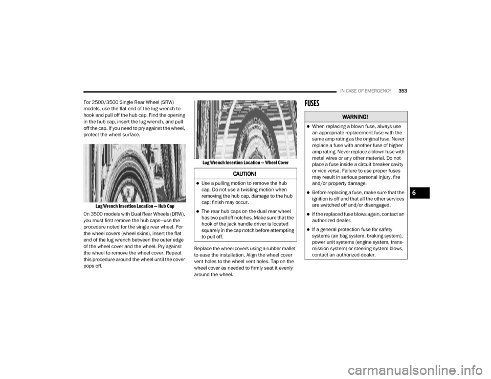
For 2500/3500 Single Rear Wheel (SRW)
models, use the flat end of the lug wrench to
hook and pull off the hub cap. Find the opening
in the hub cap, insert the lug wrench, and pull
off the cap. If you need to pry against the wheel,
protect the wheel surface.
Lug Wrench Insertion Location — Hub Cap
On 3500 models with Dual Rear Wheels (DRW),
you must first remove the hub caps—use the
procedure noted for the single rear wheel. For
the wheel covers (wheel skins), insert the flat
end of the lug wrench between the outer edge
of the wheel cover and the wheel. Pry against
the wheel to remove the wheel cover. Repeat
this procedure around the wheel until the cover
pops off.
Lug Wrench Insertion Location — Wheel Cover
Replace the wheel covers using a rubber mallet
to ease the installation. Align the wheel cover
vent holes to the wheel vent holes. Tap on the
wheel cover as needed to firmly seat it evenly
around the wheel.FUSES
CAUTION!
Use a pulling motion to remove the hub
cap. Do not use a twisting motion when
removing the hub cap, damage to the hub
cap; finish may occur.
The rear hub caps on the dual rear wheel
has two pull off notches. Make sure that the
hook of the jack handle driver is located
squarely in the cap notch before attempting
to pull off.
WARNING!
When replacing a blown fuse, always use
an appropriate replacement fuse with the
same amp rating as the original fuse. Never
replace a fuse with another fuse of higher
amp rating. Never replace a blown fuse with
metal wires or any other material. Do not
place a fuse inside a circuit breaker cavity
or vice versa. Failure to use proper fuses
may result in serious personal injury, fire
and/or property damage.
Before replacing a fuse, make sure that the
ignition is off and that all the other services
are switched off and/or disengaged.
If the replaced fuse blows again, contact an
authorized dealer.
If a general protection fuse for safety
systems (air bag system, braking system),
power unit systems (engine system, trans -
mission system) or steering system blows,
contact an authorized dealer.
6
20_DJD2_OM_EN_USC_t.book Page 353
Page 356 of 553
354IN CASE OF EMERGENCY
Power Distribution Center
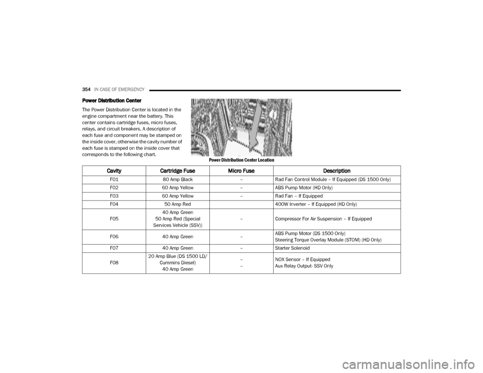
The Power Distribution Center is located in the
engine compartment near the battery. This
center contains cartridge fuses, micro fuses,
relays, and circuit breakers. A description of
each fuse and component may be stamped on
the inside cover, otherwise the cavity number of
each fuse is stamped on the inside cover that
corresponds to the following chart.
Power Distribution Center Location
CavityCartridge Fuse Micro Fuse Description
F0180 Amp Black –Rad Fan Control Module – If Equipped (DS 1500 Only)
F02 60 Amp Yellow –ABS Pump Motor (HD Only)
F03 60 Amp Yellow –Rad Fan – If Equipped
F04 50 Amp Red 400W Inverter – If Equipped (HD Only)
F05 40 Amp Green
50 Amp Red (Special
Services Vehicle (SSV)) –
Compressor For Air Suspension – If Equipped
F06 40 Amp Green –ABS Pump Motor (DS 1500 Only)
Steering Torque Overlay Module (STOM) (HD Only)
F07 40 Amp Green –Starter Solenoid
F08 20 Amp Blue (DS 1500 LD/
Cummins Diesel)40 Amp Green –
–
NOX Sensor – If Equipped
Aux Relay Output- SSV Only
20_DJD2_OM_EN_USC_t.book Page 354
Page 359 of 553

IN CASE OF EMERGENCY357
F3730 Amp Pink –Fuel Heater #2, Aux Relay 2 – If Equipped (HD Only)
SSV (DS 1500 Only)
F38 30 Amp Pink –Integrated Trailer Brake Module – If Equipped (HD Only)
Power Inverter 115 Volts AC – If Equipped (DS 1500 Only)
F39 20 Amp Blue –Power Outlet – SSV Only
F40 –10 Amp Red Ventilated Seats – If Equipped (HD Only)
F41 –10 Amp Red Active Grille Shutter / Active Air Dam – If Equipped
F42 –20 Amp Yellow Horn
F43 –15 Amp Blue Heated Steering Wheel – If Equipped (HD Only)
F44 –10 Amp Red Diagnostic Port
F46 –10 Amp RedUpfitters Relay Coil – If Equipped (HD Only)
Spare (DS 1500 Only)
F49 –10 Amp RedInstrument Panel Cluster / HVAC (DS 1500 Only)
Instrument Cluster / MOD CSG (HD Only)
F50 –20 Amp Yellow Air Suspension Control Module – If Equipped
F51 –10 Amp RedIgnition Node Module / Keyless Ignition Node Module,
Radio Frequency Hub Module / Electric Steering Column
Lock - If Equipped
F52 –5 Amp Tan Battery Sensor
F53 –20 Amp Yellow Trailer Tow – Left Turn/Stop Lights - If Equipped
F54 –20 Amp Yellow Non Memory Adjustable Pedals - If Equipped
F56 –15 Amp Blue Additional Diesel Content - If Equipped (DS 1500 Only)
CavityCartridge Fuse Micro Fuse Description
6
20_DJD2_OM_EN_USC_t.book Page 357
Page 362 of 553

360IN CASE OF EMERGENCY
F78 –10 Amp RedEngine Control Module / Powertrain Control Module /
Electric Power Steering (DS 1500 Only)
F78 –15 Amp BlueEngine Control Module / Powertrain Control Module / AEB
RACM MOD / Feed To AUX PDC Relay Coils/ HRLS (HD
Only)
F79 –15 Amp Blue ID / Clearance Lights
F80 –10 Amp RedUniversal Garage Door Opener / Compass / Anti-Intrusion
Module (DS 1500 Only)
ASSY Overhead Console / SW Assist / SW 911 – If
Equipped (HD Only)
F81 –20 Amp Yellow Trailer Tow Right Turn / Stop Lights - If Equipped
F82 –10 Amp Red Steering Column Control Module / Cruise Control
F83 ––No Connection
F84 –15 Amp Blue ASBM / HVAC / ICS / Rear Heated Seat Switches
F85 –10 Amp Red Airbag Module
F86 –10 Amp Red Airbag Module
F87 –10 Amp RedAir Suspension / ITBM / Steering Column Control Module
/ MOD Gateway CAN-C Trailer TPM (HD Only)
Air Suspension / Trailer Tow / DC/DC Converter (Voltage
Stabilizer) / Steering Column Control Module / Occupant
Classification Sensor (DS 1500 Only)
F88 –15 Amp Blue Instrument Panel Cluster
CavityCartridge Fuse Micro Fuse Description
20_DJD2_OM_EN_USC_t.book Page 360
Page 363 of 553

IN CASE OF EMERGENCY361
F90/F91 –20 Amp Yellow IGN or BATT Customer Selectable – If Equipped (HD Only)
Power Outlet (Rear Seats) Customer Selectable (DS 1500
Only)
F93 –20 Amp Yellow Cigar Lighter - If Equipped
F94 –10 Amp RedShift-By-Wire / Transfer Case Switch (DS 1500 Only)
Shift-By-Wire / Transfer Case Switch / Module TPM Trailer
(HD Only) / Module Gateway Can-C Trailer TPM (HD Only)
F95 –10 Amp RedRearview Camera / Park Assist / CHMSL Camera / Blind
Spot Sensor / Surround View Camera (HD Only)
Rear Camera / Park Assist / Blind Spot Sensor / Compass
(DS 1500 Only)
F96 –10 Amp RedRear Seat Heater Switch / Trunk Lamp With Flashlamp
Charger / Truck Lamp - If Equipped (DS 1500 Only)
Trailer Camera – If Equipped (HD Only)
F97 –25 Amp ClearRear Heated Seats And Heated Steering Wheel – If
Equipped (DS 1500 Only)
F97 –20 Amp Yellow Front Heated Seat Passenger – If Equipped (HD Only)
F98 –25 Amp Clear Front Heated Seats – If Equipped (DS 1500 Only)
F98 –20 Amp Yellow Front Heated Seat Driver – If Equipped (HD Only)
F99 –10 Amp RedHVAC / DASM (DS 1500 Only)
HVAC / In-Car Temperature Sensor / CSG MOD (HD Only)
F100 –10 Amp Red Upfitters – If Equipped (HD Only)
F101 –15 Amp Blue SSV Only
CavityCartridge Fuse Micro Fuse Description
6
20_DJD2_OM_EN_USC_t.book Page 361
Page 367 of 553

IN CASE OF EMERGENCY365
GEAR SELECTOR OVERRIDE — 6–SPEED
TRANSMISSION
If a malfunction occurs and the gear selector
cannot be moved out of the PARK position, you
can use the following procedure to temporarily
move the gear selector:
1. Turn the engine OFF.
2. Firmly apply the parking brake.
3. Tilt the steering wheel to the full up position.
4. Press and maintain firm pressure on the
brake pedal. 5. Insert a screwdriver or similar tool into the
access port (ringed circle) on the bottom of
the steering column, and push and hold the
override release lever up.
Gear Selector Override Access Port Location Gear Selector Override Access Port Engaging The Access Port
6. Move the gear selector to the NEUTRAL position.
7. The vehicle may then be started in NEUTRAL.
CAUTION!
Accessories plugged into the vehicle power
outlets draw power from the vehicle’s battery,
even when not in use (i.e., cellular devices,
etc.). Eventually, if plugged in long enough
without engine operation, the vehicle’s
battery will discharge sufficiently to degrade
battery life and/or prevent the engine from
starting.
6
20_DJD2_OM_EN_USC_t.book Page 365
Page 368 of 553

366IN CASE OF EMERGENCY
MANUAL PARK RELEASE — 8 – SPEED
TRANSMISSION
To push or tow the vehicle in cases where the
transmission will not shift out of PARK (such as
a depleted battery), a Manual Park Release is
available.
Manual Park Release Panel Cover
Manual Park Release Pull Strap
Follow these steps to activate the Manual Park
Release:
1. Firmly apply the parking brake.
2. Using a small screwdriver or similar tool,
remove the Manual Park Release access
cover, which is just above the parking brake
release handle, below and to the left of the
steering column.
3. Press and maintain firm pressure on the brake pedal.
4. Using the screwdriver or similar tool, push the Manual Park Release lever locking tab
(just below the middle of the lever) to the
right.
5. While holding the locking tab in the disen -
gaged position, pull the tether strap to
rotate the lever rearward, until it locks in
place pointing towards the driver's seat.
Release the locking tab and verify that the
Manual Park Release lever is locked in the
released position.
6. The vehicle is now out of PARK and can be towed. Release the parking brake only when
the vehicle is securely connected to a tow
vehicle.
WARNING!
Always secure your vehicle by fully applying
the parking brake before activating the
Manual Park Release. In addition, you should
be seated in the driver’s seat with your foot
firmly on the brake pedal when activating the
Manual Park Release. Activating the Manual
Park Release will allow your vehicle to roll
away if it is not secured by the parking brake,
or by proper connection to a tow vehicle.
Activating the Manual Park Release on an
unsecured vehicle could lead to serious injury
or death for those in or around the vehicle.
20_DJD2_OM_EN_USC_t.book Page 366
Page 369 of 553
IN CASE OF EMERGENCY367
To Reset The Manual Park Release:
1. Push the locking tab to the right, to unlock
the lever.
2. Rotate the Manual Park Release lever forward to its original position, until the
locking tab snaps into place to secure the
lever.
3. Pull gently on the tether strap to confirm that the lever is locked in its stowed posi-
tion.
4. Re-install the access cover.
IF YOUR ENGINE OVERHEATS
In any of the following situations, you can
reduce the potential for overheating by taking
the appropriate action.
On the highways — slow down.
In city traffic — while stopped, place the trans -
mission in NEUTRAL, but do not increase the
engine idle speed while preventing vehicle
motion with the brakes. NOTE:
There are steps that you can take to slow down
an impending overheat condition:
If your Air Conditioner (A/C) is on, turn it off.
The A/C system adds heat to the engine
cooling system and turning the A/C off can
help remove this heat.
You can also turn the temperature control to
maximum heat, the mode control to floor and
the blower control to high. This allows the
heater core to act as a supplement to the
radiator and aids in removing heat from the
engine cooling system.
FREEING A STUCK VEHICLE
If your vehicle becomes stuck in mud, sand, or
snow, it can often be moved using a rocking
motion. Turn the steering wheel right and left to
clear the area around the front wheels. Then
shift back and forth between DRIVE (D) and
REVERSE (R), while gently pressing the acceler
-
ator. Use the least amount of accelerator pedal
pressure that will maintain the rocking motion,
without spinning the wheels or racing the
engine.
WARNING!
You or others can be badly burned by hot
engine coolant (antifreeze) or steam from
your radiator. If you see or hear steam coming
from under the hood, do not open the hood
until the radiator has had time to cool. Never
try to open a cooling system pressure cap
when the radiator or coolant bottle is hot.
CAUTION!
Driving with a hot cooling system could
damage your vehicle. If the temperature
gauge reads HOT (H), pull over and stop the
vehicle. Idle the vehicle with the air
conditioner turned off until the pointer drops
back into the normal range. If the pointer
remains on HOT (H), and you hear continuous
chimes, turn the engine off immediately and
call for service.
6
20_DJD2_OM_EN_USC_t.book Page 367