instrument cluster Ram 2500 2020 Manual Online
[x] Cancel search | Manufacturer: RAM, Model Year: 2020, Model line: 2500, Model: Ram 2500 2020Pages: 553, PDF Size: 21.99 MB
Page 299 of 553
STARTING AND OPERATING297
NOTE:
ParkSense will reduce the volume of the radio,
if on, when the system is sounding an audio
tone.
Front Park Assist Audible Alerts
ParkSense will turn off the Front Park Assist
audible alert (chime) after approximately three
seconds when an obstacle has been detected,
the vehicle is stationary, and brake pedal is
applied.
Adjustable Chime Volume Settings
The Front and Rear chime volume settings are
programmable through the Uconnect system.
Refer to “Uconnect Settings” in “Multimedia”
for further information. The chime volume settings include low,
medium, and high. The factory default volume is
medium.
Enabling And Disabling Front And/Or Rear
ParkSense
Front ParkSense can be enabled and disabled
with the Front ParkSense switch.
Rear ParkSense can be enabled and disabled
with the Rear ParkSense switch.
When the gear selector is moved to
REVERSE and the Front or Rear
system is disabled, the instrument
cluster display will show a vehicle
graphic with an “Off” message overlay over the
system that is off (Front or Rear system). This
vehicle graphic will be displayed for as long as
the vehicle is in REVERSE. The Front or Rear ParkSense switch LED will be
on when Front or Rear ParkSense is disabled or
requires service. The Front or Rear ParkSense
switch LED will be off when the Front or Rear
system is enabled. If the Front or Rear Park
-
Sense switch is pushed, and the system
requires service, the Front or Rear ParkSense
switch LED will blink momentarily, and then the
LED will be on.
Service The ParkSense Front/Rear Park
Assist System
During vehicle start up, when the Front/Rear
ParkSense System has detected a faulted
condition, the instrument cluster display will
show the "Front/Rear ParkSense Unavailable
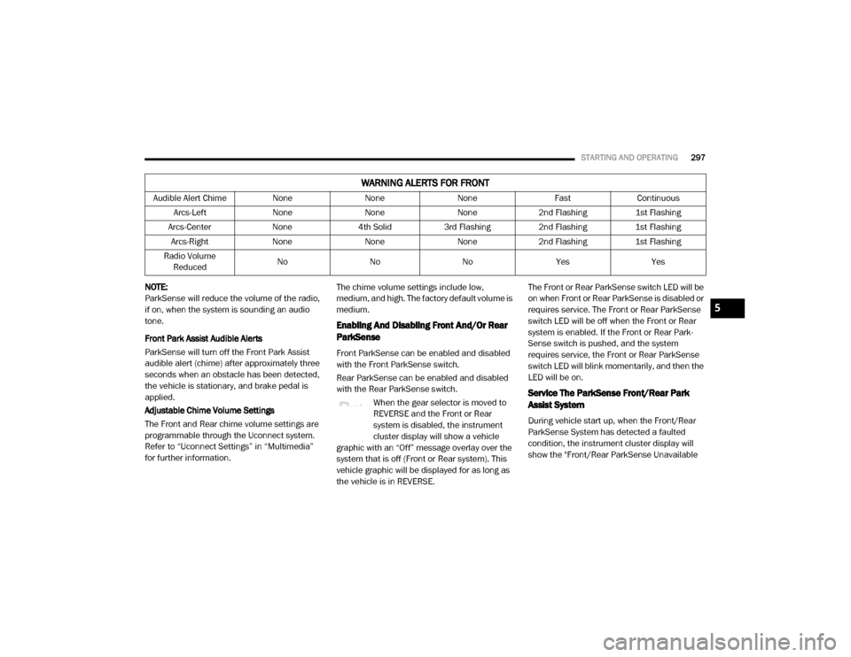
Audible Alert Chime
NoneNoneNone FastContinuous
Arcs-Left NoneNoneNone2nd Flashing 1st Flashing
Arcs-Center None4th Solid 3rd Flashing 2nd Flashing 1st Flashing
Arcs-Right NoneNoneNone2nd Flashing 1st Flashing
Radio Volume Reduced No
NoNo Yes Yes
WARNING ALERTS FOR FRONT
5
20_DJD2_OM_EN_USC_t.book Page 297
Page 300 of 553
298STARTING AND OPERATING
Service Required" or the "Front/Rear Park -
Sense Unavailable Wipe Sensors" message.
When the gear selector is moved into REVERSE,
a vehicle graphic will show in the instrument
cluster display, along with the display overlay
“Wipe Sensors.” If the system needs service,
the display overlay will read “Service.” Under
this condition, ParkSense will not operate.
If "Front/Rear ParkSense Unavailable Wipe
Sensors" appears in the instrument cluster
display make sure the outer surface and the
underside of the rear fascia/bumper is clean
and clear of snow, ice, mud, dirt or other
obstruction, and then cycle the ignition. If the
message continues to appear, see an autho -
rized dealer.
If "Front/Rear ParkSense Unavailable Service
Required" appears in the instrument cluster
display, see an authorized dealer.
Cleaning The ParkSense System
Clean the ParkSense sensors with water, car
wash soap and a soft cloth. Do not use rough or
hard cloths. Do not scratch or poke the sensors.
Otherwise, you could damage the sensors.
ParkSense System Usage Precautions
NOTE:
Ensure that the front and rear bumpers are
free of snow, ice, mud, dirt and debris to keep
the ParkSense system operating properly.
Jackhammers, large trucks, and other vibra -
tions could affect the performance of Park -
Sense.
When you move the gear selector to the
REVERSE position and Front or Rear Park -
Sense is turned off, the instrument cluster
display will show "Off" on the vehicle graphic
arcs. This vehicle graphic will be displayed for
as long as the vehicle is in REVERSE.
ParkSense, when on, will reduce the volume
of the radio when it is sounding a tone.
Clean the ParkSense sensors regularly,
taking care not to scratch or damage them.
The sensors must not be covered with ice,
snow, slush, mud, dirt or debris. Failure to do
so can result in the system not working prop -
erly. The ParkSense system might not detect an obstacle behind or in front of the fascia/
bumper, or it could provide a false indication
that an obstacle is behind or in front of the
fascia/bumper.
Use the ParkSense switch to turn the Park
-
Sense system off if obstacles such as bicycle
carriers, trailer hitches, etc. are placed within
18 inches (45 cm) from the rear fascia/
bumper. Failure to do so can result in the
system misinterpreting a close obstacle as a
sensor problem, causing the “Front/Rear
ParkSense Unavailable Service Required”
message to be appear in the instrument
cluster display.
On vehicles equipped with a tailgate, Park -
Sense should be disabled when the tailgate
is in the lowered or open position. A lowered
tailgate could provide a false indication that
an obstacle is behind the vehicle.
20_DJD2_OM_EN_USC_t.book Page 298
Page 301 of 553
STARTING AND OPERATING299
LANESENSE — IF EQUIPPED
LaneSense Operation
The LaneSense system is operational at speeds
above 37 mph (60 km/h) and below 112 mph
(180 km/h). It uses a forward looking camera to
detect lane markings and measure vehicle posi -
tion within the lane boundaries.
When both lane markings are detected and the
driver unintentionally drifts out of the lane while
no turn signal has been applied OR the driver
departs the lane on the opposite side of the
applied turn signal (if the left turn signal is applied and the vehicle departs to the right), the
LaneSense system provides a haptic warning in
the form of torque applied to the steering wheel
to prompt the driver to remain within the lane
boundaries. The LaneSense system will also
provide a visual warning through the instrument
cluster display to prompt the driver to remain
within the lane boundaries.
The driver may manually override the haptic
warning by applying torque into the steering
wheel at any time.
When only a single lane marking is detected
and the driver unintentionally drifts across that
lane marking (no turn signal applied), the Lane
-
Sense system provides a visual warning
through the instrument cluster display to
prompt the driver to remain within the lane.
When only a single lane marking is detected, a
haptic (torque) warning will not be provided.
NOTE:
When operating conditions have been met, the
LaneSense system will monitor if the driver’s
hands are on the steering wheel and provides
an audible and visual warning to the driver
when the driver’s hands are not detected on the
steering wheel. The system will cancel if the
driver does not return their hands to the wheel.
WARNING!
Drivers must be careful when backing up
even when using ParkSense. Always check
carefully behind your vehicle, look behind
you, and be sure to check for pedestrians,
animals, other vehicles, obstructions, and
blind spots before backing up. You are
responsible for safety and must continue to
pay attention to your surroundings. Failure
to do so can result in serious injury or
death.
Before using ParkSense, it is strongly
recommended that the ball mount and
hitch ball assembly is disconnected from
the vehicle when the vehicle is not used for
towing. Failure to do so can result in injury
or damage to vehicles or obstacles
because the hitch ball will be much closer
to the obstacle than the rear fascia when
the loudspeaker sounds the continuous
tone. Also, the sensors could detect the ball
mount and hitch ball assembly, depending
on its size and shape, giving a false indica -
tion that an obstacle is behind the vehicle.
CAUTION!
ParkSense is only a parking aid and it is
unable to recognize every obstacle,
including small obstacles. Parking curbs
might be temporarily detected or not
detected at all. Obstacles located above or
below the sensors will not be detected
when they are in close proximity.
The vehicle must be driven slowly when
using ParkSense in order to be able to stop
in time when an obstacle is detected. It is
recommended that the driver looks over
his/her shoulder when using ParkSense.
5
20_DJD2_OM_EN_USC_t.book Page 299
Page 302 of 553
300STARTING AND OPERATING
Turning LaneSense On Or Off
The LaneSense button is located on
the switch panel below the Uconnect
display.
NOTE:
If your vehicle is equipped with a 12–inch Ucon -
nect Display screen, the LaneSense button is
located above the display.
To turn the LaneSense system on, push the
LaneSense button (LED turns off). A “Lane -
Sense On” message is shown in the instrument
cluster display.
Lane Sense On Message
To turn the LaneSense system off, push the
LaneSense button again (LED turns on).
NOTE:
The LaneSense system will retain the last
system state (on or off) from the last ignition
cycle when the ignition is placed in the ON/RUN
position.
LaneSense Warning Message
The LaneSense system will indicate the current
lane drift condition through the instrument
cluster display.
When the LaneSense system is on, the lane
lines are gray when both of the lane boundaries
have not been detected and the LaneSense tell
-
tale is solid white.
System ON (Gray Lines) With White Telltale
Left Lane Departure — Only Left Lane Detected
When the LaneSense system is on, the Lane-
Sense Telltale is solid white when only the
left lane marking has been detected and the
system is ready to provide visual warnings in
the instrument cluster display if an uninten -
tional lane departure occurs on the left side.
When the LaneSense system senses the lane
has been approached and is in a lane depar -
ture situation, the visual warning in the
instrument cluster display will show the left
lane line flashing yellow (on/off). The Lane -
Sense telltale changes from solid white to
flashing yellow.
20_DJD2_OM_EN_USC_t.book Page 300
Page 303 of 553
STARTING AND OPERATING301
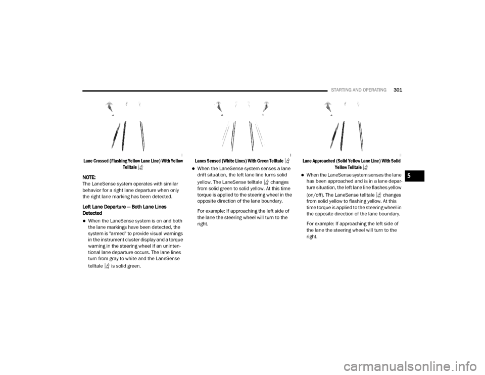
Lane Crossed (Flashing Yellow Lane Line) With Yellow
Telltale
NOTE:
The LaneSense system operates with similar
behavior for a right lane departure when only
the right lane marking has been detected.
Left Lane Departure — Both Lane Lines
Detected
When the LaneSense system is on and both
the lane markings have been detected, the
system is "armed" to provide visual warnings
in the instrument cluster display and a torque
warning in the steering wheel if an uninten -
tional lane departure occurs. The lane lines
turn from gray to white and the LaneSense
telltale is solid green.
Lanes Sensed (White Lines) With Green Telltale
When the LaneSense system senses a lane
drift situation, the left lane line turns solid
yellow. The LaneSense telltale changes
from solid green to solid yellow. At this time
torque is applied to the steering wheel in the
opposite direction of the lane boundary.
For example: If approaching the left side of
the lane the steering wheel will turn to the
right.
Lane Approached (Solid Yellow Lane Line) With Solid
Yellow Telltale
When the LaneSense system senses the lane
has been approached and is in a lane depar -
ture situation, the left lane line flashes yellow
(on/off). The LaneSense telltale changes
from solid yellow to flashing yellow. At this
time torque is applied to the steering wheel in
the opposite direction of the lane boundary.
For example: If approaching the left side of
the lane the steering wheel will turn to the
right.5
20_DJD2_OM_EN_USC_t.book Page 301
Page 315 of 553
STARTING AND OPERATING313
NOTE:
When the fuel nozzle “clicks” or shuts off, the
fuel tank is full.
Tighten the gas cap until you hear a “clicking”
sound. This is an indication that the gas cap
is tightened properly. The MIL in the instru -
ment cluster may turn on if the gas cap is not
secured properly. Make sure that the gas cap
is tightened each time the vehicle is refueled.
Loose Fuel Filler Cap Message
If the vehicle diagnostic system deter -
mines that the fuel filler cap is loose,
improperly installed, or damaged, a
loose gASCAP indicator will display in
the instrument cluster telltale display area.
Refer to “Instrument Cluster Display” in
“Getting To Know Your Instrument Panel” for
further information. Tighten the fuel filler cap
properly and push the RIGHT button to turn off
the message. If the problem continues, the
message will appear the next time the vehicle is
started.
REFUELING THE VEHICLE — DIESEL ENGINE
1. Open the fuel filler door.
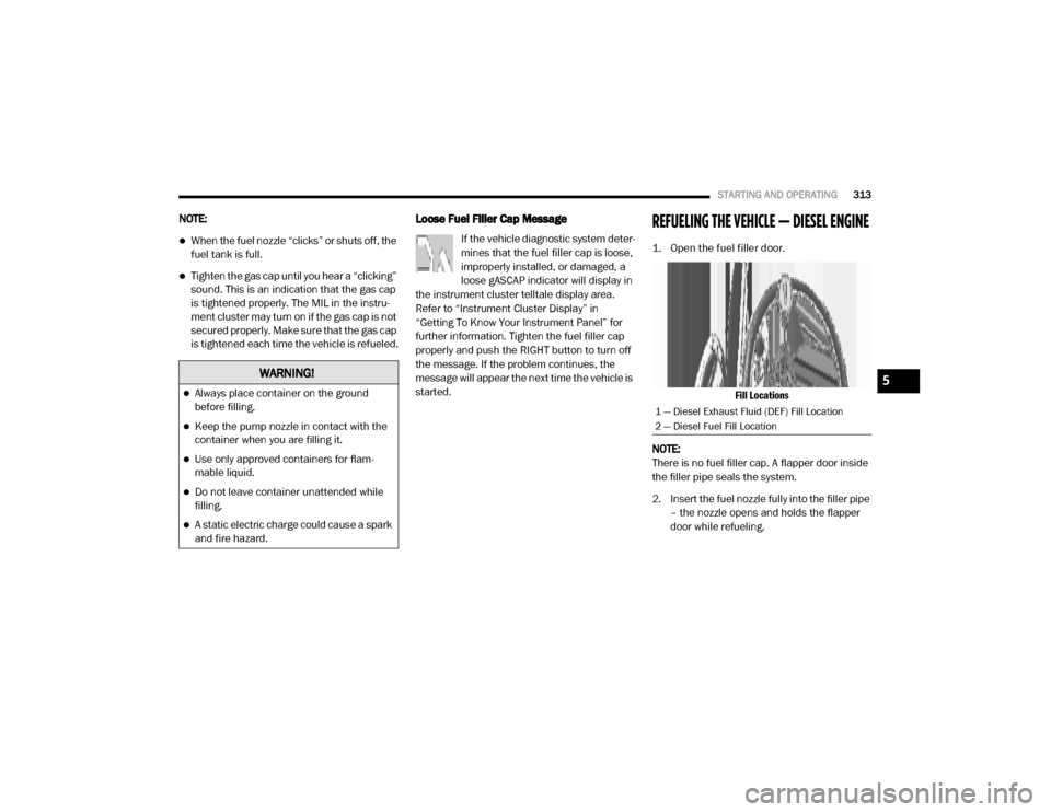
Fill Locations
NOTE:
There is no fuel filler cap. A flapper door inside
the filler pipe seals the system.
2. Insert the fuel nozzle fully into the filler pipe – the nozzle opens and holds the flapper
door while refueling.
WARNING!
Always place container on the ground
before filling.
Keep the pump nozzle in contact with the
container when you are filling it.
Use only approved containers for flam -
mable liquid.
Do not leave container unattended while
filling.
A static electric charge could cause a spark
and fire hazard.
1 — Diesel Exhaust Fluid (DEF) Fill Location
2 — Diesel Fuel Fill Location
5
20_DJD2_OM_EN_USC_t.book Page 313
Page 317 of 553

STARTING AND OPERATING315
vaporized, it converts smog-forming nitrogen
oxides (NOx) into harmless nitrogen (N2) and
water vapor (H2O), two natural components of
the air we breathe. You can operate with the
comfort that your vehicle is contributing to a
cleaner, healthier world environment for this
and generations to come.
System Overview
This vehicle is equipped with a Diesel Exhaust
Fluid (DEF) injection system and a Selective
Catalytic Reduction (SCR) catalyst to meet the
emission requirements.
The DEF injection system consists of the
following components:
DEF tank
DEF pump
DEF injector
Electronically-heated DEF lines
DEF control module
NOx sensors
Temperature sensors
SCR catalyst
UQS Sensor Refer to “Instrument Cluster Display” in
“Getting To Know Your Instrument Panel” for
system messages and warnings.
NOTE:
Your vehicle is equipped with a DEF injection
system. You may occasionally hear an
audible clicking noise. This is normal opera
-
tion.
The DEF pump will run for a period of time
after engine shutdown to purge the DEF
system. This is normal operation.
Diesel Exhaust Fluid Storage
Diesel Exhaust Fluid (DEF) is considered a very
stable product with a long shelf life. If DEF is
kept in temperatures between 10°F and 90°F
(-12°C and 32°C), it will last a minimum of one
year.
DEF is subject to freezing at the lowest tempera-
tures. For example, DEF may freeze at tempera-
tures at or below 12°F (-11°C). The system has
been designed to operate in this environment. NOTE:
When working with DEF, it is important to know
that:
Any containers or parts that come into
contact with DEF must be DEF compatible
(plastic or stainless steel). Copper, brass,
aluminum, iron or non-stainless steel should
be avoided as they are subject to corrosion
by DEF.
If DEF is spilled, it should be wiped up
completely.
Adding Diesel Exhaust Fluid
The DEF gauge (located on the instrument
cluster) will display the level of DEF remaining in
the tank. Refer to “Instrument Cluster” and
“Instrument Cluster Descriptions” in “Getting To
Know Your Instrument Panel” for further infor
-
mation.
NOTE:
Driving conditions (altitude, vehicle speed,
load, etc.) will affect the amount of DEF that
is used in your vehicle.
Another factor is that outside temperature
can affect DEF consumption. In cold condi -
tions, 12°F (-11°C) and below, the DEF
5
20_DJD2_OM_EN_USC_t.book Page 315
Page 319 of 553
STARTING AND OPERATING317
3. Stop filling the DEF tank immediately when
any of the following happen: DEF stops
flowing from the fill bottle into the DEF tank,
DEF splashes out the filler neck, or a DEF
pump nozzle automatically shuts off.
4. Reinstall cap onto DEF tank.
Filling The Def Tank In Cold Climates
Since DEF will begin to freeze at 12°F (-11°C),
your vehicle is equipped with an automatic DEF
heating system. This allows the DEF injection system to operate properly at temperatures
below 12°F (-11°C). If your vehicle is not in
operation for an extended period of time with
temperatures below 12°F (-11°C), the DEF in
the tank may freeze. If the tank is overfilled and
freezes, it could be damaged. Therefore, do not
overfill the DEF tank.
Extra care should be taken when filling with
portable containers to avoid overfilling. Note the
level of the DEF gauge in your instrument cluster.
You may safely add a maximum of 2 Gallons
(7.5 Liters) of DEF from portable containers
when your DEF gauge is reading ½ full.
VEHICLE LOADING
Gross Vehicle Weight Rating (GVWR)
The GVWR is the total permissible weight of your
vehicle including driver, passengers, vehicle,
options and cargo. The label also specifies
maximum capacities of front and rear axle
systems (GAWR). Total load must be limited so
GVWR and front and rear GAWR are not
exceeded.
Payload
The payload of a vehicle is defined as the allow
-
able load weight a truck can carry, including the
weight of the driver, all passengers, options and
cargo.
Gross Axle Weight Rating (GAWR)
The GAWR is the maximum permissible load on
the front and rear axles. The load must be
distributed in the cargo area so that the GAWR
of each axle is not exceeded.
Each axle GAWR is determined by the compo -
nents in the system with the lowest load
carrying capacity (axle, springs, tires or wheels).
Heavier axles or suspension components some -
times specified by purchasers for increased
durability does not necessarily increase the
vehicle's GVWR.
Tire Size
The tire size on the Vehicle Certification Label
represents the actual tire size on your vehicle.
Replacement tires must be equal to the load
capacity of this tire size.
Never add anything other than DEF to the
tank – especially any form of hydrocarbon
such as diesel fuel, fuel system additives,
gasoline, or any other petroleum-based
product. Even a very small amount of these,
less than 100 parts per million or less than
1 oz. per 78 Gallons (295 Liters) will
contaminate the entire DEF system and will
require replacement. If owners use a
container, funnel or nozzle when refilling
the tank, it should either be new or one that
is has only been used for adding DEF.
Mopar provides an attachable nozzle with
its DEF for this purpose.
CAUTION! (Continued)
5
20_DJD2_OM_EN_USC_t.book Page 317
Page 328 of 553
326STARTING AND OPERATING
GAIN
The GAIN setting is used to set the trailer brake
control for the specific towing condition and
should be changed as towing conditions
change. Changes to towing conditions include
trailer load, vehicle load, road conditions and
weather.
Adjusting GAIN
NOTE:
This should only be performed in a traffic free
environment at speeds of approximately
20–25 mph (30–40 km/h).
1. Make sure the trailer brakes are in good
working condition, functioning normally
and properly adjusted. See your trailer
dealer if necessary.
2. Hook up the trailer and make the electrical connections according to the trailer manu -
facturer's instructions. 3. When a trailer with electric/EOH brakes is
plugged in, the trailer connected message
should appear in the instrument cluster
display (if the connection is not recognized
by the ITBM, braking functions will not be
available), the GAIN setting will illuminate
and the correct type of trailer must be
selected from the instrument cluster display
options.
4. Push the UP or DOWN button on the steering wheel until “TRAILER TOW”
appears on the screen.
5. Push the RIGHT arrow on the steering wheel to enter “TRAILER TOW”.
6. Push the UP or DOWN buttons until the Trailer Brake Type appears on the screen. 7. Push the RIGHT arrow and then push the UP
or DOWN buttons until the proper Trailer
Brake Type appears on the screen.
8. In a traffic-free environment, tow the trailer on a dry, level surface at a speed of
20–25 mph (30–40 km/h) and squeeze
the manual brake control lever completely.
9. If the trailer wheels lockup (indicated by squealing tires), reduce the GAIN setting; if
the trailer wheels turn freely, increase the
GAIN setting.
Repeat steps 8 and 9 until the GAIN setting is at
a point just below trailer wheel lockup. If towing
a heavier trailer, trailer wheel lockup may not be
attainable even with the maximum GAIN setting
of 10.
20_DJD2_OM_EN_USC_t.book Page 326
Page 329 of 553

STARTING AND OPERATING327
* The suggested selection depends and may
change depending on the customer prefer -
ences for braking performance. Condition of the
trailer brakes, driving and road state may also
affect the selection.
Display Messages
The trailer brake control interacts with the
instrument cluster display. Display messages,
along with a single chime, will be displayed
when a malfunction is determined in the trailer
connection, trailer brake control, or on the
trailer. Refer to “Instrument Cluster Display” in
“Getting To Know Your Instrument Panel” for
further information. NOTE:
An aftermarket controller may be available
for use with trailers with air or elec
-
tric-over-hydraulic trailer brake systems. To
determine the type of brakes on your trailer
and the availability of controllers, check with
your trailer manufacturer or dealer.
Removal of the ITBM will cause errors and it
may cause damage to the electrical system
and electronic modules of the vehicle. See
your authorized dealer if an aftermarket
module is to be installed.
Towing Requirements — Trailer Lights And
Wiring
Whenever you pull a trailer, regardless of the
trailer size, stoplights and turn signals on the
trailer are required for motoring safety.
The Trailer Tow Package may include a four- and
seven-pin wiring harness. Use a factory
approved trailer harness and connector.
NOTE:
Do not cut or splice wiring into the vehicle’s
wiring harness.
The electrical connections are all complete to
the vehicle but you must mate the harness to a
trailer connector. Refer to the following illustra -
tions.
Light Electric Heavy Electric Light EOHHeavy EOH
Type of Trailer Brakes Electric Trailer Brakes Electric Trailer Brakes Electric over Hydraulic
Trailer BrakesElectric over Hydraulic
Trailer Brakes
Load *Under 10,000 lbs *Above 10,000 lbs *Under 10,000 lbs *Above 10,000 lbs
WARNING!
Connecting a trailer that is not compatible
with the ITBM system may result in reduced
or complete loss of trailer braking. There may
be a increase in stopping distance or trailer
instability which could result in personal
injury.
CAUTION!
Connecting a trailer that is not compatible
with the ITBM system may result in reduced
or complete loss of trailer braking. There may
be a increase in stopping distance or trailer
instability which could result in damage to
your vehicle, trailer, or other property.
5
20_DJD2_OM_EN_USC_t.book Page 327