instrument cluster Ram 2500 2020 Owner's Manual
[x] Cancel search | Manufacturer: RAM, Model Year: 2020, Model line: 2500, Model: Ram 2500 2020Pages: 553, PDF Size: 21.99 MB
Page 6 of 553

4
SLIDE-IN CAMPERS .......................................... 100 Camper Applications .................................100
EASY-OFF TAILGATE ......................................... 100
Disconnecting The Rear Camera And
Remote Keyless Entry ...............................100 Removing The Tailgate .............................. 101
Locking Tailgate .........................................101
TRI-FOLD TONNEAU COVER — IF EQUIPPED .. 101
Tri-Fold Tonneau Cover Removal ..............102
Tri-Fold Tonneau Cover Installation ..........104
Tri-Fold Tonneau Cover Cleaning ..............107
GETTING TO KNOW YOUR INSTRUMENT PANEL
BASE / MIDLINE INSTRUMENT CLUSTER —
GAS ENGINE ....................................................... 108
Base / Midline Instrument Cluster
Descriptions — Gas Engine .......................109
PREMIUM INSTRUMENT CLUSTER —
GAS ENGINE ....................................................... 111
Premium Instrument Cluster Descriptions —
Gas Engine .................................................112
BASE INSTRUMENT CLUSTER — DIESEL
ENGINE ............................................................... 113
Base Instrument Cluster Descriptions —
Diesel Engine .............................................114
PREMIUM INSTRUMENT CLUSTER — DIESEL
ENGINE ................................................................ 116
Premium Instrument Cluster Descriptions —
Diesel Engine .............................................117 INSTRUMENT CLUSTER DISPLAY ................... 117
Instrument Cluster Display Controls......... 118
Oil Life Reset ............................................. 119
Display Menu Items ................................... 119
Diesel Messages And Warnings — 6.7L
Cummins Diesel Engine ............................ 124 Battery Saver On/Battery Saver Mode
Message — Electrical Load Reduction
Actions — If Equipped ................................ 128
WARNING LIGHTS AND MESSAGES ................130
Red Warning Lights ................................... 130
Yellow Warning Lights ............................... 133
Yellow Indicator Lights .............................. 137
Green Indicator Lights ............................... 140
White Indicator Lights ............................... 141
Blue Indicator Lights.................................. 141
ONBOARD DIAGNOSTIC SYSTEM — OBD II..... 141
Onboard Diagnostic System (OBD II)
Cybersecurity ............................................. 142
EMISSIONS INSPECTION AND MAINTENANCE
PROGRAMS......................................................... 142
SAFETY
SAFETY FEATURES .............................................144
Anti-Lock Brake System (ABS) ................. 144
Electronic Brake Control (EBC) System .... 145 AUXILIARY DRIVING SYSTEMS ........................ 153
Blind Spot Monitoring (BSM) —
If Equipped ................................................ 153 Forward Collision Warning (FCW) With
Mitigation — If Equipped ........................... 160 Tire Pressure Monitoring System
(TPMS) ........................................................ 163
OCCUPANT RESTRAINT SYSTEMS ................. 171
Occupant Restraint Systems Features ... 171
Important Safety Precautions ................... 171
Seat Belt Systems .................................... 172
Supplemental Restraint Systems (SRS)... 181
Child Restraints ......................................... 190
Transporting Pets ...................................... 208
SAFETY TIPS ....................................................... 208
Transporting Passengers .......................... 208
Exhaust Gas .............................................. 208
Safety Checks You Should Make Inside
The Vehicle ................................................ 209 Periodic Safety Checks You Should Make
Outside The Vehicle ................................... 210
20_DJD2_OM_EN_USC_t.book Page 4
Page 7 of 553

5
STARTING AND OPERATING
STARTING THE ENGINE — GAS ENGINE ......... 211Automatic Transmission ............................211
Tip Start Feature .......................................211
Keyless Enter-N-Go — Ignition ...................211
Normal Starting Using ENGINE START/
STOP Button ...............................................212 Cold Weather Operation (Below –22°F Or
−30°C) ......................................................215 After Starting ..............................................215
STARTING THE ENGINE — DIESEL ENGINE..... 215
Automatic Transmission ............................215
Keyless Enter-N-Go — Ignition ...................216
Extreme Cold Weather...............................218
Normal Starting Procedure — Engine
Manifold Air Temperature Above 66° F
(19° C)........................................................ 218 Starting Procedure — Engine Manifold Air
Temperature 0°F To 66°F (–18°C to
19°C) ..........................................................219 Starting Procedure — Engine Manifold Air
Temperature Below 0°F (-18°C) ..............220 Starting Fluids ............................................221 NORMAL OPERATION — DIESEL ENGINE ........221
Cold Weather Precautions ........................ 222
Engine Idling ............................................. 224
Noise........................................................... 225
Stopping The Engine ................................. 225
Idle Shutdown ............................................ 226
Programmable Maximum Vehicle
Speed ......................................................... 226 Operating Precautions............................... 226
Cooling System Tips .................................. 226
ENGINE BLOCK HEATER — GAS ENGINE (IF
EQUIPPED) ..........................................................227
ENGINE BLOCK HEATER — DIESEL ENGINE (IF
EQUIPPED) ......................................................... 227
Block Heater Usage ................................... 228
ENGINE BREAK-IN RECOMMENDATIONS — GAS
ENGINE ................................................................ 228
ENGINE BREAK-IN RECOMMENDATIONS —
DIESEL ENGINE...................................................228
PARKING BRAKE ............................................... 229
DIESEL EXHAUST BRAKE — ENGINE BRAKING
(IF EQUIPPED) ....................................................230
AUTOMATIC TRANSMISSION ........................... 231
Ignition Park Interlock ............................... 232
Brake/Transmission Shift Interlock
System ....................................................... 232 Eight-Speed Automatic Transmission — If
Equipped .................................................... 233 Six-Speed Automatic Transmission — If
Equipped .................................................... 237
AUXILIARY SWITCHES — IF EQUIPPED ........... 243
ACTIVE NOISE CANCELLATION ........................ 243
FOUR-WHEEL DRIVE OPERATION —
IF EQUIPPED ...................................................... 244
Four-Position Electronically Shifted Transfer
Case — If Equipped ................................... 244
Manually Shifted Transfer Case —
If Equipped ................................................. 247
AIR SUSPENSION SYSTEM — IF EQUIPPED.... 250
Description ................................................. 250
Air Suspension Modes .............................. 251
Instrument Cluster Display Messages ..... 251
Operation ................................................... 251
AXLE LOCKER SYSTEM — POWER WAGON
MODELS ONLY (IF EQUIPPED) ......................... 252
STABILIZER/SWAY BAR SYSTEM — POWER
WAGON ONLY .................................................... 253
20_DJD2_OM_EN_USC_t.book Page 5
Page 16 of 553
14GETTING TO KNOW YOUR VEHICLE
TIP:
When viewing a topic, tap the star icon to add it
to your Favorites, for easy access in the future.
KEYS
Key Fob
Your vehicle uses a keyless ignition system. The
ignition system consists of a key fob and a
START/STOP push button ignition system. The
Remote Keyless Entry (RKE) system consists of
a key fob and Keyless Enter-N-Go feature.
NOTE:
The key fob may not be found if it is located next
to a mobile phone, laptop or other electronic
device; these devices may block the key fob’s
wireless signal.
The key fob allows you to lock or unlock all
doors, tailgate, and the RamBox (if equipped),
as well as release the tailgate, and activate the
Panic Alarm from distances up to approximately
66 ft (20 m). The key fob does not need to be
pointed at the vehicle to activate the system. NOTE:
In the ON/RUN position, all key fob buttons
will work until the vehicle reaches 2 mph
(4 km/h).
The key fob should not be placed next to the
wireless charging pad (if equipped).
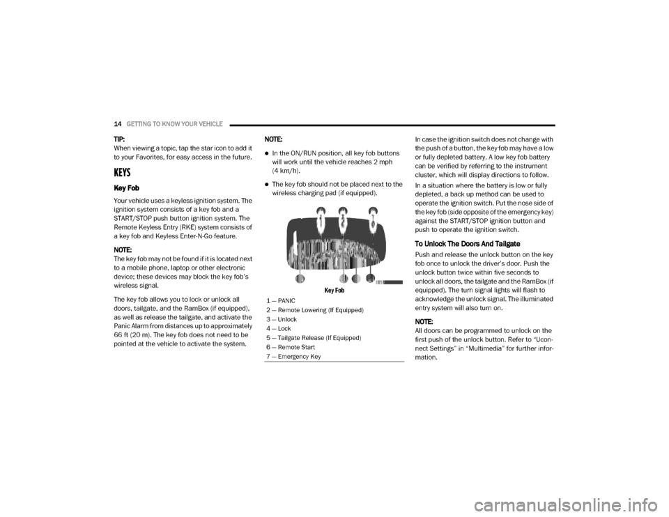
Key Fob
In case the ignition switch does not change with
the push of a button, the key fob may have a low
or fully depleted battery. A low key fob battery
can be verified by referring to the instrument
cluster, which will display directions to follow.
In a situation where the battery is low or fully
depleted, a back up method can be used to
operate the ignition switch. Put the nose side of
the key fob (side opposite of the emergency key)
against the START/STOP ignition button and
push to operate the ignition switch.
To Unlock The Doors And Tailgate
Push and release the unlock button on the key
fob once to unlock the driver’s door. Push the
unlock button twice within five seconds to
unlock all doors, the tailgate and the RamBox (if
equipped). The turn signal lights will flash to
acknowledge the unlock signal. The illuminated
entry system will also turn on.
NOTE:
All doors can be programmed to unlock on the
first push of the unlock button. Refer to “Ucon
-
nect Settings” in “Multimedia” for further infor -
mation.
1 — PANIC
2 — Remote Lowering (If Equipped)
3 — Unlock
4 — Lock
5 — Tailgate Release (If Equipped)
6 — Remote Start
7 — Emergency Key
20_DJD2_OM_EN_USC_t.book Page 14
Page 22 of 553
20GETTING TO KNOW YOUR VEHICLE
REMOTE START — IF EQUIPPED
(GASOLINE)
This system uses the key fob to start
the engine conveniently from outside
the vehicle while still maintaining
security. The system has a range of
approximately 300 ft (91 m).
NOTE:
Obstructions between the vehicle and the key
fob may reduce this range.
How To Use Remote Start
All of the following conditions must be met
before the engine will remote start:
Gear selector in PARK
Doors closed
Hood closed
Hazard switch off
Brake switch inactive (brake pedal not
pushed)
Battery at an acceptable charge level
PANIC button not pushed
Fuel meets minimum requirement
System not disabled from previous remote
start event
Vehicle security alarm not active
Malfunction Indicator Light is not illuminated
Remote Start Abort Message
The following messages will display in the
instrument cluster display if the vehicle fails to
remote start or exits remote start prematurely:
Remote Start Cancelled — Door Open
Remote Start Cancelled — Hood Open
Remote Start Cancelled — Fuel Low
Remote Start Cancelled — System Fault
Remote Start Disabled — Start Vehicle to
Reset
The instrument cluster display message stays
active until the ignition is placed in the ON/RUN
position.
To Enter Remote Start Mode
Push and release the Remote Start
button on the key fob twice within five
seconds. The parking lights will flash,
vehicle doors will lock, and the horn
will chirp twice (if programmed). Once the
vehicle has started, the engine will run for
15 minutes.
WARNING!
Do not start or run an engine in a closed
garage or confined area. Exhaust gas
contains Carbon Monoxide (CO) which is
odorless and colorless. Carbon Monoxide is
poisonous and can cause serious injury or
death when inhaled.
Keep key fobs away from children. Opera -
tion of the Remote Start System, windows,
door locks or other controls could cause
serious injury or death.
20_DJD2_OM_EN_USC_t.book Page 20
Page 25 of 553
GETTING TO KNOW YOUR VEHICLE23
Remote Start Abort Message
The following messages will display in the
instrument cluster display if the vehicle fails to
remote start or exits remote start prematurely:
Remote Start Aborted — Door Open
Remote Start Aborted — Hood Open
Remote Start Aborted — Fuel Low
Remote Start Aborted — System Fault
The instrument cluster display message is
stored until the ignition is placed in the ON/RUN
position.
To Enter Remote Start Mode
Push and release the Remote Start button on
the key fob twice, within five seconds. The
parking lights will flash and the horn will chirp
twice (if programmed). In cold ambient
temperature conditions, the diesel vehicle may
delay crank up to 30 seconds for the Intake Air
Heater. Once the vehicle has started, the
engine will run for 15 minutes.
NOTE:
Crank may be delayed up to 75 seconds for
intake air heater operation at high altitudes,
and/or extreme cold.
The park lamps will turn on and remain on
during Remote Start mode.
For security, power window and power
sunroof operation (if equipped) are disabled
when the vehicle is in the Remote Start
mode.
Additional features, such as windshield
wipers, will also not be available while the
vehicle is in the Remote Start mode.
The engine can be started two consecutive
times (two 15 minute cycles) with the key
fob. However, the ignition switch must be placed in the ON/RUN position before you
can repeat the start sequence for a third
cycle.
To Exit Remote Start Mode Without Driving
The Vehicle
Push and release the Remote Start button one
time or allow the engine to run for the entire
15 minute cycle.
NOTE:
To avoid unintentional shut downs, the system
will disable for two seconds after receiving a
valid Remote Start request.
To Exit Remote Start Mode And Drive The
Vehicle
To exit Remote Start Mode and drive the vehicle
before the end of the 15 minute cycle, push and
release the unlock button on the key fob to
unlock the door and disarm the vehicle security
alarm System (if equipped). Then, prior to the
end of the 15 minute cycle, place the ignition in
the ON/RUN position.
NOTE:
The ignition switch must be in the ON/RUN posi
-
tion in order to drive the vehicle.
WARNING!
Do not start or run an engine in a closed
garage or confined area. Exhaust gas
contains Carbon Monoxide (CO) which is
odorless and colorless. Carbon Monoxide is
poisonous and can cause serious injury or
death when inhaled.
Keep key fobs away from children. Opera -
tion of the Remote Start System, windows,
door locks or other controls could cause
serious injury or death.
2
20_DJD2_OM_EN_USC_t.book Page 23
Page 33 of 553
GETTING TO KNOW YOUR VEHICLE31
Automatic Door Locks — If Equipped
The auto door lock feature default condition is
enabled. When enabled, the door locks will lock
automatically when the vehicle's speed exceeds
15 mph (24 km/h). The auto door lock feature
can be enabled or disabled by an authorized
dealer per written request of the customer.
Please see an authorized dealer for service.
Automatic Doors Unlock — If Equipped
This feature unlocks all of the doors of the vehicle
when either front door is opened. This will occur
only after the vehicle has been shifted into the
PARK position after the vehicle has been driven
(shifted out of PARK and all doors closed).
Automatic Doors Unlock Programming — If
Equipped
The Automatic Doors Unlock feature can be
enabled or disabled as follows:
For vehicles not equipped with a touchscreen
radio, refer to “Instrument Cluster Display” in
“Getting To Know Your Instrument Panel” for
further information.
For vehicles equipped with a touchscreen
radio, refer to “Uconnect Settings” in “Multi -
media” for further information. NOTE:
Use the Auto Unlock Doors feature in accor
-
dance with local laws.
Child-Protection Door Lock
To provide a safer environment for children
riding in the rear seat, the rear doors (if
equipped) of your vehicle have the Child-Protec -
tion Door Lock system.
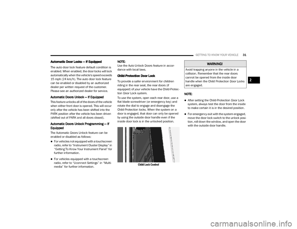
To use the system, open each rear door, use a
flat blade screwdriver (or emergency key) and
rotate the dial to engage and disengage the
Child-Protection locks. When the system on a
door is engaged, that door can only be opened
by using the outside door handle even if the
inside door lock is in the unlocked position.
Child Lock Control
NOTE:
After setting the Child-Protection Door Lock
system, always test the door from the inside
to make certain it is in the desired position.
For emergency exit with the system engaged,
move the door lock switch to the unlock posi
-
tion, roll down the window, and open the door
with the outside door handle.
WARNING!
Avoid trapping anyone in the vehicle in a
collision. Remember that the rear doors
cannot be opened from the inside door
handle when the Child Protection Door Locks
are engaged.
2
20_DJD2_OM_EN_USC_t.book Page 31
Page 38 of 553

36GETTING TO KNOW YOUR VEHICLE
4. Within five seconds, push and release
either of the memory buttons (1) or (2). The
instrument cluster display will show which
memory position has been set.
NOTE:
Memory profiles can be set without the vehicle
in PARK.
Linking And Unlinking The Remote Keyless
Entry Key Fob To Memory
Your key fob can be programmed to recall one
of two pre-programmed memory profiles by
pushing the unlock button on the key fob.
NOTE:
Before programming your key fob you must
select the “Personal Settings Linked to Key
Fob” feature through the Uconnect Settings.
Refer to “Uconnect Settings” in “Multimedia”
for further information.
To program your key fob, perform the following:
1. Place the vehicle’s ignition in the OFF posi -
tion.
2. Select a desired memory profile 1 or 2. NOTE:
If a memory profile has not already been set,
refer to "Programming The Memory Feature" in
this section for instructions on how to set a
memory profile.
3. Once the profile has been recalled, push
and release the set (S) button on the
memory switch.
4. Push and release button (1) or (2) accord -
ingly. “Memory Profile Set” (1 or 2) will
display in the instrument cluster.
5. Push and release the lock button on the key fob within 10 seconds.
NOTE:
Your key fob can be unlinked to your memory
settings by pushing the set (S) button, and
within 10 seconds, followed by pushing the
unlock button on the key fob.
Memory Position Recall
NOTE:
The vehicle speed must be lower than 5 mph
(8 km/h) to recall memory positions. If a recall
is attempted when the vehicle speed is greater than 5 mph (8 km/h), a message will be
displayed in the instrument cluster display.
Driver One Memory Position Recall
To recall the memory settings for driver one
using the memory buttons on the door panel,
push memory button (1).
To recall the memory settings for driver one
using the key fob, push the unlock button on
the key fob linked to memory position 1.
Driver Two Memory Position Recall
To recall the memory setting for driver two
using the memory buttons on the door panel,
push memory button (2).
To recall the memory settings for driver two
using the key fob, push the unlock button on
the key fob linked to memory position 2.
A recall can be cancelled by pushing any of the
memory buttons during a recall (S, 1, or 2).
When a recall is canceled, the driver's seat and
the adjustable pedals (if equipped) stop
moving. A delay of one second will occur before
another recall can be selected.
20_DJD2_OM_EN_USC_t.book Page 36
Page 54 of 553
52GETTING TO KNOW YOUR VEHICLE
light switch is on, and then the headlight switch
is cycled off. Headlight delay can be canceled by
either turning the headlight switch on then off,
or by placing the ignition in the ON/RUN posi -
tion.
NOTE:
This feature can be programmed through the
Uconnect system. Refer to “Uconnect Settings”
in “Multimedia” for further information.
Lights-On Reminder
If the headlights, parking lights, or cargo lights
are left on after the ignition is placed in the OFF
position, a chime will sound and a message will
appear in the instrument cluster display when
the driver’s door is opened.
Front Fog Lights — If Equipped
To activate the front fog lights, turn on the
parking lights or low beam headlights and push
in the center of the headlight switch control
knob. Pushing the headlight switch control knob
a second time will turn the front fog lights off.
Front Fog Light Switch
Turn Signals
Move the multifunction lever up or down and
the arrows on each side of the instrument
cluster display will flash to show proper opera
-
tion of the front and rear turn signal lights.
NOTE:
If either light remains on and does not flash, or
there is a very fast flash rate, check for a defec -
tive outside light bulb. If an indicator fails to
light when the lever is moved, it would suggest
that the indicator bulb is defective.
Lane Change Assist — If Equipped
Tap the multifunction lever up or down once,
without moving beyond the detent, and the turn signal (right or left) will flash three times then
automatically turn off.
Cargo Lights/Trailer Spotter Lights With Bed
Lights — If Equipped
The cargo light and bed lights (if equipped) and
trailer spotter lights (if equipped) are turned on
by pushing the cargo lights button located on
the lower half of the headlight switch.
Cargo/Bed Lights Button On Headlight Switch
If the vehicle’s speed is 0 mph (0 km/h), these
lights can also be turned on using the switch
located just inside the pickup box, on the lower
part of the bed light lens. A telltale will illumi -
nate in the instrument cluster display when
these lights are on. Pushing the switch a second
time will turn the lights off.
20_DJD2_OM_EN_USC_t.book Page 52
Page 110 of 553

108
GETTING TO KNOW YOUR INSTRUMENT PANEL
BASE / MIDLINE INSTRUMENT CLUSTER — GAS ENGINE
Base / Midline Instrument Cluster — Gas Engine
20_DJD2_OM_EN_USC_t.book Page 108
Page 111 of 553
GETTING TO KNOW YOUR INSTRUMENT PANEL109
Base / Midline Instrument Cluster
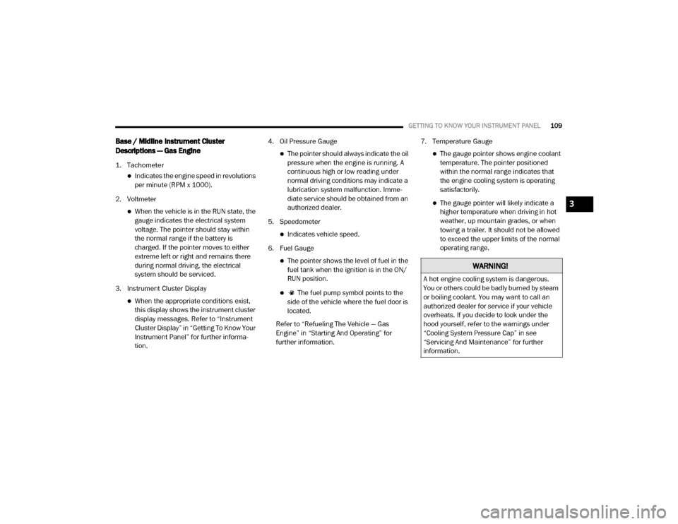
Descriptions — Gas Engine
1. Tachometer
Indicates the engine speed in revolutions
per minute (RPM x 1000).
2. Voltmeter
When the vehicle is in the RUN state, the gauge indicates the electrical system
voltage. The pointer should stay within
the normal range if the battery is
charged. If the pointer moves to either
extreme left or right and remains there
during normal driving, the electrical
system should be serviced.
3. Instrument Cluster Display
When the appropriate conditions exist, this display shows the instrument cluster
display messages. Refer to “Instrument
Cluster Display” in “Getting To Know Your
Instrument Panel” for further informa -
tion. 4. Oil Pressure Gauge
The pointer should always indicate the oil
pressure when the engine is running. A
continuous high or low reading under
normal driving conditions may indicate a
lubrication system malfunction. Imme -
diate service should be obtained from an
authorized dealer.
5. Speedometer
Indicates vehicle speed.
6. Fuel Gauge
The pointer shows the level of fuel in the fuel tank when the ignition is in the ON/
RUN position.
The fuel pump symbol points to the
side of the vehicle where the fuel door is
located.
Refer to “Refueling The Vehicle — Gas
Engine” in “Starting And Operating” for
further information. 7. Temperature Gauge
The gauge pointer shows engine coolant
temperature. The pointer positioned
within the normal range indicates that
the engine cooling system is operating
satisfactorily.
The gauge pointer will likely indicate a higher temperature when driving in hot
weather, up mountain grades, or when
towing a trailer. It should not be allowed
to exceed the upper limits of the normal
operating range.
WARNING!
A hot engine cooling system is dangerous.
You or others could be badly burned by steam
or boiling coolant. You may want to call an
authorized dealer for service if your vehicle
overheats. If you decide to look under the
hood yourself, refer to the warnings under
“Cooling System Pressure Cap” in see
“Servicing And Maintenance” for further
information.
3
20_DJD2_OM_EN_USC_t.book Page 109