Perform service message Ram 2500 2020 Owner's Manual
[x] Cancel search | Manufacturer: RAM, Model Year: 2020, Model line: 2500, Model: Ram 2500 2020Pages: 553, PDF Size: 21.99 MB
Page 10 of 553

8
ENHANCED ACCIDENT RESPONSE SYSTEM
(EARS) ................................................................ 371
EVENT DATA RECORDER (EDR) ....................... 371
BULB REPLACEMENT ........................................ 372 Replacement Bulbs ...................................372
Replacing Exterior Bulbs ...........................374
SERVICING AND MAINTENANCE
SCHEDULED SERVICING — GAS ENGINE ....... 380Maintenance Plan — Gasoline Engine......380
Heavy Duty Use Of The Vehicle ................. 384
SCHEDULED SERVICING— DIESEL ENGINE .... 384
Oil Change Indicator System — Cummins
Diesel ..........................................................385 Perform Service Indicator — Cummins
Diesel ..........................................................385
Maintenance Plan — Cummins Diesel
Engine ........................................................ 386
ENGINE COMPARTMENT .................................. 391
6.4L Engine ...............................................391
6.7L Diesel Engine — Six-Speed 68RFE ..392
6.7L Diesel Engine — Six-Speed
AS69RC HD ................................................393 Checking Oil Level — Gas Engine .............394
Checking Oil Level — Diesel Engine ..........394
Adding Washer Fluid..................................394
Maintenance-Free Battery .......................395
Pressure Washing ......................................395 DEALER SERVICE ..............................................396
Engine Oil .................................................. 396
Engine Oil Filter .......................................... 398
Engine Air Cleaner Filter............................ 398
Air Conditioner Maintenance .................... 400
Accessory Drive Belt Inspection ............... 403
Draining Fuel/Water Separator Filter —
Diesel Engine ............................................ 403 Engine Mounted Fuel Filter Replacement —
Diesel Engine ............................................. 405 Underbody Mounted Fuel Filter
Replacement — Diesel Engine .................. 406 Priming If The Engine Has Run Out Of
Fuel — Diesel Engine ................................. 407 Intervention Regeneration Strategy —
Message Process Flow ............................. 407 Diesel Exhaust Fluid .................................. 408
Body Lubrication ........................................ 408
Windshield Wiper Blades .......................... 409
Exhaust System ........................................ 410
Cooling System ......................................... 411
Charge Air Cooler — Inter-Cooler .............. 415
Brake System ............................................ 415
Automatic Transmission............................ 416
Rear Axle And 4x4 Front Driving Axle Fluid
Level .......................................................... 418 Transfer Case ............................................ 419
Noise Control System Required
Maintenance & Warranty ......................... 419 HOISTING ........................................................... 422
TIRES ................................................................... 422
Tire Safety Information.............................. 422
Tires — General Information .................... 428
Tire Types ................................................... 432
Spare Tires — If Equipped ......................... 433
Wheel And Wheel Trim Care ..................... 434
Tire Chains And Traction Devices ............ 435
Tire Rotation Recommendations ............. 436
DEPARTMENT OF TRANSPORTATION UNIFORM
TIRE QUALITY GRADES .................................... 438
Treadwear .................................................. 438
Traction Grades ......................................... 438
Temperature Grades ................................. 438
STORING THE VEHICLE ..................................... 439
BODYWORK ........................................................ 439
Protection From Atmospheric Agents....... 439
Body And Underbody Maintenance .......... 439
Preserving The Bodywork.......................... 440
INTERIORS ......................................................... 442
Seats And Fabric Parts .............................. 442
Plastic And Coated Parts........................... 442
Leather Parts ............................................. 443
Glass Surfaces .......................................... 443
20_DJD2_OM_EN_USC_t.book Page 8
Page 127 of 553
GETTING TO KNOW YOUR INSTRUMENT PANEL125
Your vehicle has the ability to alert you to addi-
tional maintenance required on your vehicle or
engine. The following messages may display in
your instrument cluster display:
Perform Service — Your vehicle will require
emissions maintenance at a set interval. To
help remind you when this maintenance is
due, the instrument cluster display will
display “Perform Service”. When the
“Perform Service” message is displayed in
the instrument cluster display it is necessary
to have the emissions maintenance
performed. Emissions maintenance may
include replacing the Closed Crankcase
Ventilation (CCV) filter element. The proce -
dure for clearing and resetting the "Perform
Service" indicator message is located in the
appropriate Service Information.
Exhaust System — Regeneration Required
Now — "Exhaust Filter XX% Full Safely Drive at
Highway Speeds to Remedy" will be displayed
in the instrument cluster display if the
exhaust particulate filter reaches 80% of its
maximum storage capacity. Under conditions
of exclusive short duration and low speed
driving cycles, your Cummins diesel engine
and exhaust after-treatment system may
never reach the conditions required to
remove the trapped Particulate Matter (PM).
If this occurs, the “Exhaust Filter XX% Full
Safely Drive at Highway Speeds to Remedy”
message will be displayed in the instrument
cluster display. If this message is displayed,
you will hear one chime to assist in alerting
you of this condition
By simply driving your vehicle at highway
speeds for as little as 45 minutes, you can
remedy the condition in the particulate filter
system and allow your Cummins diesel
engine and exhaust after-treatment system
to remove the trapped Particulate Matter
(PM) and restore the system to normal oper -
ating condition.Exhaust System — Regeneration In Process
Exhaust Filter XX% Full — Indicates that the
Diesel Particulate Filter (DPF) is self-cleaning.
Maintain your current driving condition until
regeneration is completed.
Exhaust System — Regeneration Completed
— This message indicates that the Diesel
Particulate Filter (DPF) self-cleaning is
completed. If this message is displayed, you
will hear one chime to assist in alerting you of
this condition.
Exhaust Service Required — See Dealer Now
— This message indicates regeneration has
been disabled due to a system malfunction.
At this point the engine Powertrain Control
Module (PCM) will register a fault code, the
instrument panel will display a MIL light.
WARNING!
A hot exhaust system can start a fire if you
park over materials that can burn. Such
materials might be grass or leaves coming
into contact with your exhaust system. Do not
park or operate your vehicle in areas where
your exhaust system can contact anything
that can burn.
CAUTION!
See an authorized dealer, as damage to the
exhaust system could occur soon with
continued operation.
3
20_DJD2_OM_EN_USC_t.book Page 125
Page 128 of 553
126GETTING TO KNOW YOUR INSTRUMENT PANEL
Exhaust Filter Full — Power Reduced See
Dealer — This message indicates the PCM
has derated the engine to limit the likelihood
of permanent damage to the after-treatment
system. If this condition is not corrected and
a dealer service is not performed, extensive
exhaust after-treatment damage can occur.
To correct this condition it will be necessary
to have your vehicle serviced by your local
authorized dealer.
NOTE:
Failing to follow the oil change indicator,
changing your oil and resetting the oil change
indicator by 0 miles remaining will prevent the
diesel exhaust filter from performing it's
cleaning routine. This will shortly result in a
Malfunction Indicator Light (MIL) and reduced
engine power. Only an authorized dealer will be
able to correct this condition.Cold Ambient Derate Mode Messages
The vehicle will display messages when a
derate (engine power reduction) is activated to
protect the engine during start up in cold
ambient temperatures.
Engine Power Reduced During Warmup —
This message will display during start up
when the ambient temperature is between
10°F (-12°C) and -10°F (-23°C).
Engine Power Reduced Up To 30 Sec
(Seconds) During Warmup — This message
will display during start up when the ambient
temperature is between -10°F (-23°C) and
-25°F (-32°C).
Engine Power Reduced Up To 2 Min
(Minutes) During Warmup — This message
will display during start up when the ambient
temperature is -25°F (-32°C) and below.
Your vehicle is equipped with an engine
warm up protection feature that may limit
engine performance after cold starting at low
ambient temperatures. The length of time
engine speed is limited is dependent upon
engine coolant temperature. Engine speed
may be briefly limited to 1000 RPM after
starting with coolant temperature below freezing conditions, and may be limited to
1000 RPM for up to approximately 2 minutes
under more severe cold conditions.
Coolant Low
— This telltale will turn on to indi -
cate the vehicle coolant level is low. Refer to
“Dealer Service” in “Servicing And Mainte -
nance” for more information.
Diesel Exhaust Fluid (DEF) Warning
Messages
There are four different messages which are
displayed if the vehicle detects that the DEF
system has been filled with a fluid other than
DEF, has experienced component failures, or
when tampering has been detected. The vehicle
may be limited to a maximum speed of 5 MPH
(8 km/H) if the DEF system is not serviced
within less than 200 miles (322 km) of the fault
being detected.
When the DEF system needs to be serviced the
following warnings will display:
DEF Low Refill Soon — This message will
display when the low level is reached, during
vehicle start up, and with increased
frequency during vehicle operation. It will be
accompanied by a single chime. Approxi -
mately 5 gallons (19 Liters) of DEF is required
to refill the tank when this message is initially CAUTION!
See an authorized dealer, as damage to the
exhaust system could occur soon with
continued operation.
20_DJD2_OM_EN_USC_t.book Page 126
Page 130 of 553
128GETTING TO KNOW YOUR INSTRUMENT PANEL
value where it stopped when a previous fault
was temporarily remedied, or at a minimum of
50 miles (80 km).
5 MPH Max Speed on Restart, Long Idle or
Refuel Service DEF See Dealer — This
message will continuously display when the
mileage counter reaches zero, and will be
accompanied by a periodic chime.
The vehicle will only be capable of a
maximum speed of 5 MPH upon the first of
the following conditions to occur:
If the vehicle is shutoff and restarted.
If the vehicle is idled for an extended
period of time, approximately one hour or
greater.
If the system detects that the level of fuel in the tank has increased.
5 MPH Max Speed Service DEF System See
Dealer — This message will continuously
display, and will be accompanied by a peri -
odic chime. Although the vehicle can be
started and placed in gear, the vehicle will
only operate at a maximum speed of 5 MPH.
Your vehicle will require towing, see an
authorized dealer for service. NOTE:
When this message is displayed, the engine can
still be started. However, the vehicle will only
operate at a maximum speed of 5 MPH.
Incorrect DEF Detected See Dealer
— This
message will display when the fault is initially
detected, each time the vehicle is started,
and periodically during driving. The message
will be accompanied by a single chime. We
recommend you drive to your nearest autho -
rized dealer and have your vehicle serviced
as soon as possible.
RAM Active Air System
Your vehicle is equipped with an advanced Ram
Active Air system that provides enhanced
performance, especially when towing under
demanding hot or high altitude conditions. If the
instrument cluster display displays the
message “Active Airbox Service Required See
Dealer”, vehicle performance may be reduced
until service is performed by an authorized RAM
dealer.
Battery Saver On/Battery Saver Mode
Message — Electrical Load Reduction
Actions — If Equipped
This vehicle is equipped with an Intelligent
Battery Sensor (IBS) to perform additional moni -
toring of the electrical system and status of the
vehicle battery.
In cases when the IBS detects charging system
failure, or the vehicle battery conditions are
deteriorating, electrical load reduction actions
will take place to extend the driving time and
distance of the vehicle. This is done by reducing
power to or turning off non-essential electrical
loads.
Load reduction is only active when the engine is
running. It will display a message if there is a
risk of battery depletion to the point where the
vehicle may stall due to lack of electrical supply,
or will not restart after the current drive cycle.
When load reduction is activated, the message
“Battery Saver On Some Systems May Have
Reduced Power” will appear in the instrument
cluster.
These messages indicate the vehicle battery
has a low state of charge and continues to lose
electrical charge at a rate that the charging
system cannot sustain.
20_DJD2_OM_EN_USC_t.book Page 128
Page 132 of 553
130GETTING TO KNOW YOUR INSTRUMENT PANEL
After a trip:
Check if any aftermarket equipment was
installed (additional lights, upfitter electrical
accessories, audio systems, alarms) and
review specifications if any (load and Ignition
Off Draw currents).
Evaluate the latest driving cycles (distance,
driving time and parking time).
The vehicle should have service performed if
the message is still present during consecu-
tive trips and the evaluation of the vehicle
and driving pattern did not help to identify the
cause.
WARNING LIGHTS AND MESSAGES
The warning/indicator lights will illuminate in
the instrument panel together with a dedicated
message and/or acoustic signal when appli -
cable. These indications are indicative and
precautionary and as such must not be consid -
ered as exhaustive. Always refer to the informa-
tion in this chapter in the event of a failure
indication. All active telltales will display first if
applicable. The system check menu may
appear different based upon equipment
options and current vehicle status. Some tell -
tales are optional and may not appear.
Red Warning Lights
Seat Belt Reminder Warning Light
This warning light indicates when the
driver or passenger seat belt is
unbuckled. When the ignition is first
placed in the ON/RUN or ACC/ON/
RUN position and if the driver’s seat belt is
unbuckled, a chime will sound and the light will
turn on. When driving, if the driver or front
passenger seat belt remains unbuckled, the
Seat Belt Reminder Light will flash or remain on
continuously and a chime will sound.
Refer to “Occupant Restraint Systems” in
“Safety” for further information.
Air Bag Warning Light
This warning light will illuminate to
indicate a fault with the air bag, and
will turn on for four to eight seconds
as a bulb check when the ignition is
placed in the ON/RUN or ACC/ON/RUN posi -
tion. This light will illuminate with a single chime
when a fault with the air bag has been detected,
it will stay on until the fault is cleared. If the light
is either not on during startup, stays on, or turns
on while driving, have the system inspected at
an authorized dealer as soon as possible.
Brake Warning Light
This warning light monitors various
brake functions, including brake fluid
level and parking brake application. If
the brake light turns on it may indi -
cate that the parking brake is applied, that the
brake fluid level is low, or that there is a
problem with the anti-lock brake system reser -
voir.
If the light remains on when the parking brake
has been disengaged, and the fluid level is at
the full mark on the master cylinder reservoir, it
indicates a possible brake hydraulic system
malfunction or that a problem with the Brake
Booster has been detected by the Anti-Lock
Brake System (ABS) / Electronic Stability
Control (ESC) system. In this case, the light will
remain on until the condition has been
corrected. If the problem is related to the brake
booster, the ABS pump will run when applying
the brake, and a brake pedal pulsation may be
felt during each stop.
The dual brake system provides a reserve
braking capacity in the event of a failure to a
portion of the hydraulic system. A leak in either
half of the dual brake system is indicated by the
Brake Warning Light, which will turn on when
20_DJD2_OM_EN_USC_t.book Page 130
Page 238 of 553
236STARTING AND OPERATING
Transmission Limp Home Mode
Transmission function is monitored electroni -
cally for abnormal conditions. If a condition is
detected that could result in transmission
damage, Transmission Limp Home Mode is acti -
vated. In this mode, the transmission may
operate only in certain gears, or may not shift at
all. Vehicle performance may be severely
degraded and the engine may stall. In some
situations, the transmission may not re-engage
if the engine is turned off and restarted. The
Malfunction Indicator Light (MIL) may be illumi -
nated. A message in the instrument cluster will
inform the driver of the more serious conditions,
and indicate what actions may be necessary.
In the event of a momentary problem, the trans -
mission can be reset to regain all forward gears
by performing the following steps:
NOTE:
In cases where the instrument cluster message
indicates the transmission may not re-engage
after engine shutdown, perform this procedure
only in a desired location (preferably, at an
authorized dealer).
1. Stop the vehicle.
2. Shift the transmission into PARK, if
possible. If not, shift the transmission to
NEUTRAL.
3. Push and hold the ignition switch until the engine turns off.
4. Wait approximately 30 seconds.
5. Restart the engine.
6. Shift into the desired gear range. If the problem is no longer detected, the trans -
mission will return to normal operation.
NOTE:
Even if the transmission can be reset, we
recommend that you visit an authorized dealer
at your earliest possible convenience. An autho -
rized dealer has diagnostic equipment to
assess the condition of your transmission.
If the transmission cannot be reset, authorized
dealer service is required.
Electronic Range Select (ERS) Operation
The Electronic Range Select (ERS) shift control
allows the driver to limit the highest available
gear when the transmission is in DRIVE. For
example, if you set the transmission gear limit
to 4 (FOURTH gear), the transmission will not shift above FOURTH gear (except to prevent
engine overspeed), but will shift through the
lower gears normally.
You can switch between DRIVE and ERS mode
at any vehicle speed. When the transmission
gear selector is in DRIVE, the transmission will
operate automatically, shifting between all
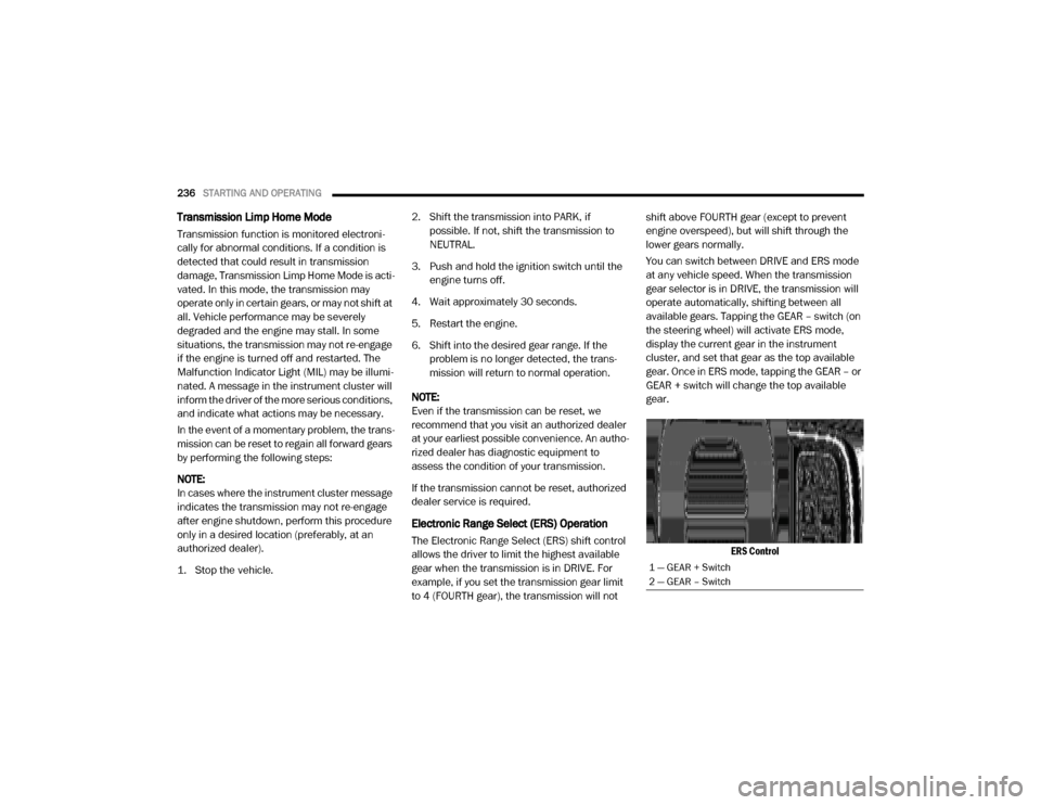
available gears. Tapping the GEAR – switch (on
the steering wheel) will activate ERS mode,
display the current gear in the instrument
cluster, and set that gear as the top available
gear. Once in ERS mode, tapping the GEAR – or
GEAR + switch will change the top available
gear.
ERS Control
1 — GEAR + Switch
2 — GEAR – Switch
20_DJD2_OM_EN_USC_t.book Page 236
Page 253 of 553
STARTING AND OPERATING251
Air Suspension Modes
The air suspension system has multiple modes
to protect the system in unique situations:
Tire/Jack Mode
To assist with changing a tire, the air suspen -
sion system has a feature which allows the
automatic leveling to be disabled. This mode is
intended to be enabled with the engine running.
Refer to “Instrument Cluster Display” in
“Getting To Know Your Instrument Panel” or
“Uconnect Settings” in “Multimedia” (if
equipped with a touch screen radio) for further
information.
NOTE:
This mode is intended to be enabled with the
engine running.
Transport Mode
For towing your vehicle with four wheels off the
road, the air suspension system has a feature
which will put the vehicle below Normal Ride
Height (NRH) and disable the automatic load
leveling system. This mode is intended to be
enabled with engine running. Refer to “Instru -
ment Cluster Display” in “Getting To Know Your
Instrument Panel” or “Uconnect Settings” in
“Understanding Your Instrument Panel” if equipped with a touch screen radio for further
information.
NOTE:
This mode is intended to be enabled with the
engine running.
Wheel Alignment Mode
Before performing a wheel alignment this mode
must be enabled. Refer to “Instrument Cluster
Display” in “Getting To Know Your Instrument
Panel” or “Uconnect Settings” in “Multimedia”
(if equipped with a touch screen radio) for
further information.
NOTE:
This mode is intended to be enabled with the
engine running.
Bed Lowering Mode
This setting is used to lower the rear suspension
to the lowest possible height and disable the air
suspension system. It enables easier loading/
unloading of the truck and makes it easier to
hook up trailers. Refer to “Instrument Cluster
Display” in “Getting To Know Your Instrument
Panel” or “Uconnect Settings” in “Under
-
standing Your Instrument Panel” if equipped with a touch screen radio for further informa
-
tion.
Protection Strategy
In order to “protect” the air suspension system,
the vehicle will disable load leveling as required
(suspension overloaded, battery charge low,
etc.). Load leveling will automatically resume as
soon as system operation requirements are
met. See your authorized dealer if system does
not resume.
Instrument Cluster Display Messages
When the appropriate conditions exist, a
message will appear in the instrument cluster
display. Refer to “Instrument Cluster Display” in
“Getting To Know Your Instrument Panel” for
further information.
An audible chime will be heard whenever a
system error has been detected.
See your authorized dealer for system service if
normal operation does not resume.
Operation
Pushing the Alternate Trailer Height (ATH)
button once while at Normal Ride Height (NRH),
will lower the vehicle to Alternate Trailer Height
(ATH) and will illuminate the LED.
5
20_DJD2_OM_EN_USC_t.book Page 251
Page 286 of 553
284STARTING AND OPERATING
malfunction or failure and require a sensor
realignment.
Do not attach or install any accessories near
the sensor, including transparent material or
aftermarket grilles. Doing so could cause an
ACC system failure or malfunction.
When the condition that deactivated the system
is no longer present, the system will return to
the “Adaptive Cruise Control Off” state and will
resume function by simply reactivating it.
NOTE:
If the “ACC/FCW Unavailable Wipe Front
Radar Sensor” message occurs frequently
(e.g. more than once on every trip) without
any snow, rain, mud, or other obstruction,
have the radar sensor realigned at your
authorized dealer.
Installing a snow plow, front-end protector,
an aftermarket grille or modifying the grille is
not recommended. Doing so may block the
sensor and inhibit ACC/FCW operation.
“Clean Front Windshield” Warning
The “ACC/FCW Limited Functionality Clean
Front Windshield” warning will display and also
a chime will indicate when conditions tempo -rarily limit system performance. This most often
occurs at times of poor visibility, such as in
snow or heavy rain and fog. The ACC system
may also become temporarily blinded due to
obstructions, such as mud, dirt, or ice on wind
-
shield, driving directly into the sun and fog on
the inside of glass. In these cases, the instru -
ment cluster display will show “ACC/FCW
Limited Functionality Clean Front Windshield”
and the system will have degraded perfor -
mance.
The “ACC/FCW Limited Functionality Clean
Front Windshield” message can sometimes be
displayed while driving in adverse weather
conditions. The ACC/FCW system will recover
after the vehicle has left these areas. Under
rare conditions, when the camera is not
tracking any vehicles or objects in its path this
warning may temporarily occur.
If weather conditions are not a factor, the driver
should examine the windshield and the camera
located on the back side of the inside rearview
mirror. They may require cleaning or removal of
an obstruction.
When the condition that created limited func -
tionality is no longer present, the system will
return to full functionality. NOTE:
If the “ACC/FCW Limited Functionality Clean
Front Windshield” message occurs frequently
(e.g. more than once on every trip) without any
snow, rain, mud, or other obstruction, have the
windshield and forward facing camera
inspected at your authorized dealer.
Service ACC/FCW Warning
If the system turns off, and the instrument
cluster displays “ACC/FCW Unavailable Service
Required” or “Cruise/FCW Unavailable Service
Required”, there may be an internal system
fault or a temporary malfunction that limits ACC
functionality. Although the vehicle is still driv
-
able under normal conditions, ACC will be
temporarily unavailable. If this occurs, try acti -
vating ACC again later, following an ignition
cycle. If the problem persists, see your autho -
rized dealer.
Precautions While Driving With ACC
In certain driving situations, ACC may have
detection issues. In these cases, ACC may
brake late or unexpectedly. The driver needs to
stay alert and may need to intervene.
20_DJD2_OM_EN_USC_t.book Page 284
Page 294 of 553
292STARTING AND OPERATING
Adjustable Chime Volume Settings
The rear chime volume settings are program -
mable through the Uconnect system. Refer to
“Uconnect Settings” in “Multimedia” for further
information.
The chime volume settings include low,
medium, and high. The factory default volume is
medium.
Enabling And Disabling ParkSense
ParkSense can be enabled and disabled with
the ParkSense switch.
When the gear selector is moved to
REVERSE and the system is disabled,
the instrument cluster display will
show the vehicle graphic with “Off”
over the arcs for as long as the vehicle is in
REVERSE.
NOTE:
The ParkSense system will automatically
disable when the system detects that a trailer
with trailer brakes has been connected to the
Integrated Trailer Brake Module. The instru -
ment cluster display will show an “Off” message over the arcs if the ParkSense system is off, or
a “Trailer” message if the system is on, for as
long as the vehicle is in REVERSE.
The ParkSense switch LED will be on when Park-
Sense is disabled or defective. The ParkSense
switch LED will be off when the system is
enabled.
If the ParkSense switch is pushed, and the
system is disabled or requires service, the Park-
Sense switch LED will blink momentarily, and
then the LED will be on.
Service The ParkSense Rear Park Assist
System
During vehicle start up, when the Rear Park
-
Sense System has detected a faulted condition,
the instrument cluster display will show the
"Rear ParkSense Unavailable Service Required"
or the "Rear ParkSense Unavailable Wipe
Sensors" message.
When the gear selector is moved into REVERSE,
a vehicle graphic will show in the instrument
cluster display, along with the display overlay
“Rear ParkSense Unavailable Wipe Sensors.” If
the system needs service, the display overlay
will read “Rear ParkSense Unavailable Service Required” Under this condition, ParkSense will
not operate.
If "Rear ParkSense Unavailable Wipe Sensors"
appears in the instrument cluster display make
sure the outer surface and the underside of the
rear fascia/bumper is clean and clear of snow,
ice, mud, dirt or other obstruction, and then
cycle the ignition. If the message continues to
appear, see an authorized dealer.
If "Rear ParkSense Unavailable Service
Required" appears in the instrument cluster
display, see an authorized dealer.
Cleaning The ParkSense System
Clean the ParkSense sensors with water, car
wash soap and a soft cloth. Do not use rough or
hard cloths. Do not scratch or poke the sensors.
Otherwise, you could damage the sensors.
ParkSense System Usage Precautions
NOTE:
Ensure that the rear bumper is free of snow,
ice, mud, dirt and debris to keep the Park
-
Sense system operating properly.
Jackhammers, large trucks, and other vibra -
tions could affect the performance of Park -
Sense.
20_DJD2_OM_EN_USC_t.book Page 292
Page 300 of 553
298STARTING AND OPERATING
Service Required" or the "Front/Rear Park -
Sense Unavailable Wipe Sensors" message.
When the gear selector is moved into REVERSE,
a vehicle graphic will show in the instrument
cluster display, along with the display overlay
“Wipe Sensors.” If the system needs service,
the display overlay will read “Service.” Under
this condition, ParkSense will not operate.
If "Front/Rear ParkSense Unavailable Wipe
Sensors" appears in the instrument cluster
display make sure the outer surface and the
underside of the rear fascia/bumper is clean
and clear of snow, ice, mud, dirt or other
obstruction, and then cycle the ignition. If the
message continues to appear, see an autho -
rized dealer.
If "Front/Rear ParkSense Unavailable Service
Required" appears in the instrument cluster
display, see an authorized dealer.
Cleaning The ParkSense System
Clean the ParkSense sensors with water, car
wash soap and a soft cloth. Do not use rough or
hard cloths. Do not scratch or poke the sensors.
Otherwise, you could damage the sensors.
ParkSense System Usage Precautions
NOTE:
Ensure that the front and rear bumpers are
free of snow, ice, mud, dirt and debris to keep
the ParkSense system operating properly.
Jackhammers, large trucks, and other vibra -
tions could affect the performance of Park -
Sense.
When you move the gear selector to the
REVERSE position and Front or Rear Park -
Sense is turned off, the instrument cluster
display will show "Off" on the vehicle graphic
arcs. This vehicle graphic will be displayed for
as long as the vehicle is in REVERSE.
ParkSense, when on, will reduce the volume
of the radio when it is sounding a tone.
Clean the ParkSense sensors regularly,
taking care not to scratch or damage them.
The sensors must not be covered with ice,
snow, slush, mud, dirt or debris. Failure to do
so can result in the system not working prop -
erly. The ParkSense system might not detect an obstacle behind or in front of the fascia/
bumper, or it could provide a false indication
that an obstacle is behind or in front of the
fascia/bumper.
Use the ParkSense switch to turn the Park
-
Sense system off if obstacles such as bicycle
carriers, trailer hitches, etc. are placed within
18 inches (45 cm) from the rear fascia/
bumper. Failure to do so can result in the
system misinterpreting a close obstacle as a
sensor problem, causing the “Front/Rear
ParkSense Unavailable Service Required”
message to be appear in the instrument
cluster display.
On vehicles equipped with a tailgate, Park -
Sense should be disabled when the tailgate
is in the lowered or open position. A lowered
tailgate could provide a false indication that
an obstacle is behind the vehicle.
20_DJD2_OM_EN_USC_t.book Page 298