transmission fluid Ram 2500 2020 Owner's Manual
[x] Cancel search | Manufacturer: RAM, Model Year: 2020, Model line: 2500, Model: Ram 2500 2020Pages: 553, PDF Size: 21.99 MB
Page 7 of 553

5
STARTING AND OPERATING
STARTING THE ENGINE — GAS ENGINE ......... 211Automatic Transmission ............................211
Tip Start Feature .......................................211
Keyless Enter-N-Go — Ignition ...................211
Normal Starting Using ENGINE START/
STOP Button ...............................................212 Cold Weather Operation (Below –22°F Or
−30°C) ......................................................215 After Starting ..............................................215
STARTING THE ENGINE — DIESEL ENGINE..... 215
Automatic Transmission ............................215
Keyless Enter-N-Go — Ignition ...................216
Extreme Cold Weather...............................218
Normal Starting Procedure — Engine
Manifold Air Temperature Above 66° F
(19° C)........................................................ 218 Starting Procedure — Engine Manifold Air
Temperature 0°F To 66°F (–18°C to
19°C) ..........................................................219 Starting Procedure — Engine Manifold Air
Temperature Below 0°F (-18°C) ..............220 Starting Fluids ............................................221 NORMAL OPERATION — DIESEL ENGINE ........221
Cold Weather Precautions ........................ 222
Engine Idling ............................................. 224
Noise........................................................... 225
Stopping The Engine ................................. 225
Idle Shutdown ............................................ 226
Programmable Maximum Vehicle
Speed ......................................................... 226 Operating Precautions............................... 226
Cooling System Tips .................................. 226
ENGINE BLOCK HEATER — GAS ENGINE (IF
EQUIPPED) ..........................................................227
ENGINE BLOCK HEATER — DIESEL ENGINE (IF
EQUIPPED) ......................................................... 227
Block Heater Usage ................................... 228
ENGINE BREAK-IN RECOMMENDATIONS — GAS
ENGINE ................................................................ 228
ENGINE BREAK-IN RECOMMENDATIONS —
DIESEL ENGINE...................................................228
PARKING BRAKE ............................................... 229
DIESEL EXHAUST BRAKE — ENGINE BRAKING
(IF EQUIPPED) ....................................................230
AUTOMATIC TRANSMISSION ........................... 231
Ignition Park Interlock ............................... 232
Brake/Transmission Shift Interlock
System ....................................................... 232 Eight-Speed Automatic Transmission — If
Equipped .................................................... 233 Six-Speed Automatic Transmission — If
Equipped .................................................... 237
AUXILIARY SWITCHES — IF EQUIPPED ........... 243
ACTIVE NOISE CANCELLATION ........................ 243
FOUR-WHEEL DRIVE OPERATION —
IF EQUIPPED ...................................................... 244
Four-Position Electronically Shifted Transfer
Case — If Equipped ................................... 244
Manually Shifted Transfer Case —
If Equipped ................................................. 247
AIR SUSPENSION SYSTEM — IF EQUIPPED.... 250
Description ................................................. 250
Air Suspension Modes .............................. 251
Instrument Cluster Display Messages ..... 251
Operation ................................................... 251
AXLE LOCKER SYSTEM — POWER WAGON
MODELS ONLY (IF EQUIPPED) ......................... 252
STABILIZER/SWAY BAR SYSTEM — POWER
WAGON ONLY .................................................... 253
20_DJD2_OM_EN_USC_t.book Page 5
Page 9 of 553

7
PARKVIEW REAR BACK UP CAMERA ............. 302 AUX Camera — If Equipped .......................304
SURROUND VIEW CAMERA SYSTEM — IF
EQUIPPED ........................................................... 305
AUX Camera — If Equipped .......................311
ENGINE RUNAWAY — DIESEL ENGINE ............ 312
REFUELING THE VEHICLE — GAS ENGINE ..... 312
Loose Fuel Filler Cap Message ................313
REFUELING THE VEHICLE — DIESEL
ENGINE ............................................................... 313
Diesel Exhaust Fluid ..................................314
VEHICLE LOADING ............................................. 317
Gross Vehicle Weight Rating (GVWR) ......317
Payload .......................................................317
Gross Axle Weight Rating (GAWR) ............317
Tire Size ......................................................317
Rim Size......................................................318
Inflation Pressure ......................................318
Curb Weight................................................318
Loading .......................................................318
TRAILER TOWING .............................................. 318
Common Towing Definitions .....................318
Trailer Hitch Type and Maximum Trailer
Weight.........................................................322 Trailer Towing Weights (Maximum Trailer
Weight Ratings) ..........................................323 Trailer And Tongue Weight ........................ 323
Towing Requirements ...............................323
Towing Tips ................................................328 SNOWPLOW ....................................................... 329
Before Plowing ........................................... 329
Snowplow Prep Package Model
Availability .................................................. 330 Over The Road Operation With Snowplow
Attached ..................................................... 330 Operating Tips ............................................ 330
General Maintenance................................ 330
RECREATIONAL TOWING (BEHIND
MOTORHOME, ETC.) .......................................... 331
Towing This Vehicle Behind Another
Vehicle ........................................................ 331 Recreational Towing — Two-Wheel Drive
Models ........................................................ 331 Recreational Towing — Four-Wheel Drive
Models ........................................................ 332
DRIVING TIPS ...................................................... 335
Driving On Slippery Surfaces ................... 335
Driving Through Water .............................. 335
Off-Road Driving Tips ................................. 336
IN CASE OF EMERGENCY
HAZARD WARNING FLASHERS........................338
ASSIST AND SOS SYSTEM — IF EQUIPPED..... 338
General Information .................................. 342 JACKING AND TIRE CHANGING ...................... 342
Jack Location ............................................. 343
Removal Of Jack And Tools....................... 343
Removing The Spare Tire .......................... 345
Preparations For Jacking .......................... 346
Jacking Instructions................................... 347
To Stow The Flat Or Spare ....................... 350
Reinstalling The Jack And Tools ............... 352
Hub Caps/Wheel Covers — If Equipped ... 352
FUSES .................................................................. 353
Power Distribution Center ........................ 354
JUMP STARTING ............................................... 362
Preparations For Jump Start ..................... 363
Jump Starting Procedure .......................... 363
GEAR SELECTOR OVERRIDE — 6–SPEED
TRANSMISSION ................................................ 365
MANUAL PARK RELEASE — 8 – SPEED
TRANSMISSION ................................................ 366
IF YOUR ENGINE OVERHEATS ......................... 367
FREEING A STUCK VEHICLE ............................ 367
TOWING A DISABLED VEHICLE ........................ 369
Two-Wheel Drive Models ........................... 370
Four-Wheel Drive Models .......................... 370
Emergency Tow Hooks — If Equipped ...... 371
20_DJD2_OM_EN_USC_t.book Page 7
Page 10 of 553

8
ENHANCED ACCIDENT RESPONSE SYSTEM
(EARS) ................................................................ 371
EVENT DATA RECORDER (EDR) ....................... 371
BULB REPLACEMENT ........................................ 372 Replacement Bulbs ...................................372
Replacing Exterior Bulbs ...........................374
SERVICING AND MAINTENANCE
SCHEDULED SERVICING — GAS ENGINE ....... 380Maintenance Plan — Gasoline Engine......380
Heavy Duty Use Of The Vehicle ................. 384
SCHEDULED SERVICING— DIESEL ENGINE .... 384
Oil Change Indicator System — Cummins
Diesel ..........................................................385 Perform Service Indicator — Cummins
Diesel ..........................................................385
Maintenance Plan — Cummins Diesel
Engine ........................................................ 386
ENGINE COMPARTMENT .................................. 391
6.4L Engine ...............................................391
6.7L Diesel Engine — Six-Speed 68RFE ..392
6.7L Diesel Engine — Six-Speed
AS69RC HD ................................................393 Checking Oil Level — Gas Engine .............394
Checking Oil Level — Diesel Engine ..........394
Adding Washer Fluid..................................394
Maintenance-Free Battery .......................395
Pressure Washing ......................................395 DEALER SERVICE ..............................................396
Engine Oil .................................................. 396
Engine Oil Filter .......................................... 398
Engine Air Cleaner Filter............................ 398
Air Conditioner Maintenance .................... 400
Accessory Drive Belt Inspection ............... 403
Draining Fuel/Water Separator Filter —
Diesel Engine ............................................ 403 Engine Mounted Fuel Filter Replacement —
Diesel Engine ............................................. 405 Underbody Mounted Fuel Filter
Replacement — Diesel Engine .................. 406 Priming If The Engine Has Run Out Of
Fuel — Diesel Engine ................................. 407 Intervention Regeneration Strategy —
Message Process Flow ............................. 407 Diesel Exhaust Fluid .................................. 408
Body Lubrication ........................................ 408
Windshield Wiper Blades .......................... 409
Exhaust System ........................................ 410
Cooling System ......................................... 411
Charge Air Cooler — Inter-Cooler .............. 415
Brake System ............................................ 415
Automatic Transmission............................ 416
Rear Axle And 4x4 Front Driving Axle Fluid
Level .......................................................... 418 Transfer Case ............................................ 419
Noise Control System Required
Maintenance & Warranty ......................... 419 HOISTING ........................................................... 422
TIRES ................................................................... 422
Tire Safety Information.............................. 422
Tires — General Information .................... 428
Tire Types ................................................... 432
Spare Tires — If Equipped ......................... 433
Wheel And Wheel Trim Care ..................... 434
Tire Chains And Traction Devices ............ 435
Tire Rotation Recommendations ............. 436
DEPARTMENT OF TRANSPORTATION UNIFORM
TIRE QUALITY GRADES .................................... 438
Treadwear .................................................. 438
Traction Grades ......................................... 438
Temperature Grades ................................. 438
STORING THE VEHICLE ..................................... 439
BODYWORK ........................................................ 439
Protection From Atmospheric Agents....... 439
Body And Underbody Maintenance .......... 439
Preserving The Bodywork.......................... 440
INTERIORS ......................................................... 442
Seats And Fabric Parts .............................. 442
Plastic And Coated Parts........................... 442
Leather Parts ............................................. 443
Glass Surfaces .......................................... 443
20_DJD2_OM_EN_USC_t.book Page 8
Page 133 of 553
GETTING TO KNOW YOUR INSTRUMENT PANEL131
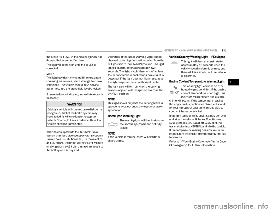
the brake fluid level in the master cylinder has
dropped below a specified level.
The light will remain on until the cause is
corrected.
NOTE:
The light may flash momentarily during sharp
cornering maneuvers, which change fluid level
conditions. The vehicle should have service
performed, and the brake fluid level checked.
If brake failure is indicated, immediate repair is
necessary.
Vehicles equipped with the Anti-Lock Brake
System (ABS) are also equipped with Electronic
Brake Force Distribution (EBD). In the event of
an EBD failure, the Brake Warning Light will turn
on along with the ABS Light. Immediate repair to
the ABS system is required. Operation of the Brake Warning Light can be
checked by turning the ignition switch from the
OFF position to the ON/RUN position. The light
should illuminate for approximately two
seconds. The light should then turn off unless
the parking brake is applied or a brake fault is
detected. If the light does not illuminate, have
the light inspected by an authorized dealer.
The light also will turn on when the parking
brake is applied with the ignition switch in the
ON/RUN position.
NOTE:
This light shows only that the parking brake is
applied. It does not show the degree of brake
application.
Hood Open Warning Light
This warning light will illuminate when
the hood is ajar/open and not fully
closed.
NOTE:
If the vehicle is moving, there will also be a
single chime.
Vehicle Security Warning Light — If Equipped
This light will flash at a fast rate for
approximately 15 seconds when the
vehicle security alarm is arming, and
then will flash slowly until the vehicle
is disarmed.
Engine Coolant Temperature Warning Light
This warning light warns of an over -
heated engine condition. If the engine
coolant temperature is too high, this
indicator will illuminate and a single
chime will sound. If the temperature reaches
the upper limit, a continuous chime will sound
for four minutes or until the engine is able to
cool; whichever comes first.
If the light turns on while driving, safely pull over
and stop the vehicle. If the Air Conditioning
(A/C) system is on, turn it off. Also, shift the
transmission into NEUTRAL and idle the vehicle.
If the temperature reading does not return to
normal, turn the engine off immediately and call
for service.
Refer to “If Your Engine Overheats” in “In Case
Of Emergency” for further information.
WARNING!
Driving a vehicle with the red brake light on is
dangerous. Part of the brake system may
have failed. It will take longer to stop the
vehicle. You could have a collision. Have the
vehicle checked immediately.
3
20_DJD2_OM_EN_USC_t.book Page 131
Page 134 of 553
132GETTING TO KNOW YOUR INSTRUMENT PANEL
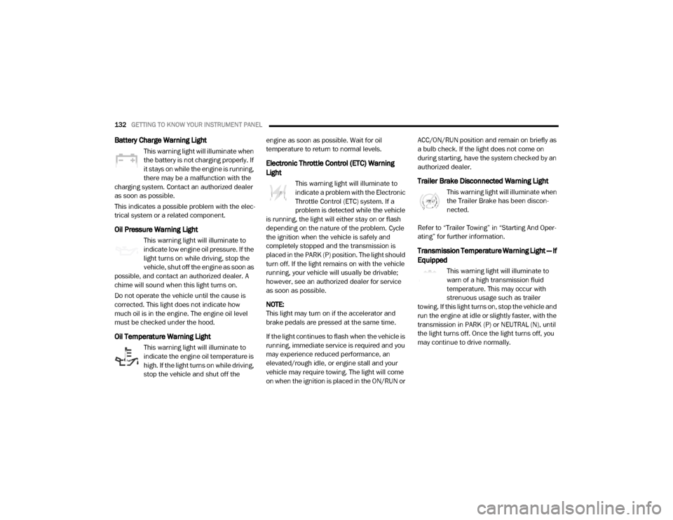
Battery Charge Warning Light
This warning light will illuminate when
the battery is not charging properly. If
it stays on while the engine is running,
there may be a malfunction with the
charging system. Contact an authorized dealer
as soon as possible.
This indicates a possible problem with the elec -
trical system or a related component.
Oil Pressure Warning Light
This warning light will illuminate to
indicate low engine oil pressure. If the
light turns on while driving, stop the
vehicle, shut off the engine as soon as
possible, and contact an authorized dealer. A
chime will sound when this light turns on.
Do not operate the vehicle until the cause is
corrected. This light does not indicate how
much oil is in the engine. The engine oil level
must be checked under the hood.
Oil Temperature Warning Light
This warning light will illuminate to
indicate the engine oil temperature is
high. If the light turns on while driving,
stop the vehicle and shut off the engine as soon as possible. Wait for oil
temperature to return to normal levels.
Electronic Throttle Control (ETC) Warning
Light
This warning light will illuminate to
indicate a problem with the Electronic
Throttle Control (ETC) system. If a
problem is detected while the vehicle
is running, the light will either stay on or flash
depending on the nature of the problem. Cycle
the ignition when the vehicle is safely and
completely stopped and the transmission is
placed in the PARK (P) position. The light should
turn off. If the light remains on with the vehicle
running, your vehicle will usually be drivable;
however, see an authorized dealer for service
as soon as possible.
NOTE:
This light may turn on if the accelerator and
brake pedals are pressed at the same time.
If the light continues to flash when the vehicle is
running, immediate service is required and you
may experience reduced performance, an
elevated/rough idle, or engine stall and your
vehicle may require towing. The light will come
on when the ignition is placed in the ON/RUN or ACC/ON/RUN position and remain on briefly as
a bulb check. If the light does not come on
during starting, have the system checked by an
authorized dealer.Trailer Brake Disconnected Warning Light
This warning light will illuminate when
the Trailer Brake has been discon
-
nected.
Refer to “Trailer Towing” in “Starting And Oper -
ating” for further information.
Transmission Temperature Warning Light — If
Equipped
This warning light will illuminate to
warn of a high transmission fluid
temperature. This may occur with
strenuous usage such as trailer
towing. If this light turns on, stop the vehicle and
run the engine at idle or slightly faster, with the
transmission in PARK (P) or NEUTRAL (N), until
the light turns off. Once the light turns off, you
may continue to drive normally.
20_DJD2_OM_EN_USC_t.book Page 132
Page 135 of 553
GETTING TO KNOW YOUR INSTRUMENT PANEL133
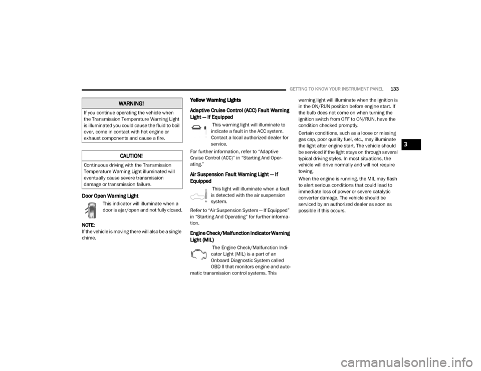
Door Open Warning Light
This indicator will illuminate when a
door is ajar/open and not fully closed.
NOTE:
If the vehicle is moving there will also be a single
chime.
Yellow Warning Lights
Adaptive Cruise Control (ACC) Fault Warning
Light — If Equipped
This warning light will illuminate to
indicate a fault in the ACC system.
Contact a local authorized dealer for
service.
For further information, refer to “Adaptive
Cruise Control (ACC)” in “Starting And Oper -
ating.”
Air Suspension Fault Warning Light — If
Equipped
This light will illuminate when a fault
is detected with the air suspension
system.
Refer to “Air Suspension System — If Equipped”
in “Starting And Operating” for further informa -
tion.
Engine Check/Malfunction Indicator Warning
Light (MIL)
The Engine Check/Malfunction Indi -
cator Light (MIL) is a part of an
Onboard Diagnostic System called
OBD II that monitors engine and auto -
matic transmission control systems. This warning light will illuminate when the ignition is
in the ON/RUN position before engine start. If
the bulb does not come on when turning the
ignition switch from OFF to ON/RUN, have the
condition checked promptly.
Certain conditions, such as a loose or missing
gas cap, poor quality fuel, etc., may illuminate
the light after engine start. The vehicle should
be serviced if the light stays on through several
typical driving styles. In most situations, the
vehicle will drive normally and will not require
towing.
When the engine is running, the MIL may flash
to alert serious conditions that could lead to
immediate loss of power or severe catalytic
converter damage. The vehicle should be
serviced by an authorized dealer as soon as
possible if this occurs.
WARNING!
If you continue operating the vehicle when
the Transmission Temperature Warning Light
is illuminated you could cause the fluid to boil
over, come in contact with hot engine or
exhaust components and cause a fire.
CAUTION!
Continuous driving with the Transmission
Temperature Warning Light illuminated will
eventually cause severe transmission
damage or transmission failure.
3
20_DJD2_OM_EN_USC_t.book Page 133
Page 227 of 553
STARTING AND OPERATING225
1. With the transmission in PARK, the parking
brake applied, and the engine running,
push the speed control switch to the ON
position, then push the SET switch.
2. The engine RPM will go up to 1,100 RPM. To increase the RPM, push and hold the
ACCEL/RESUME switch and the idle speed
will increase to approximately 1,500 RPM.
To decrease the RPM, push and hold the
DECEL switch and the idle speed will
decrease to approximately 1,100 RPM.
3. To cancel the Idle–Up feature, either push the CANCEL switch, push the ON/OFF
switch, or press the brake pedal.
Noise
Diesel engines can create noises that may
seem concerning. The nature of a diesel engine
is compression ignition where compressed air and fuel are mixed and ignited. Weather, baro
-
metric pressure, altitude, and temperature will
affect how fuel is ignited in the engine. Engines
will sound different from day to day or previous
model years. Clicking, ticking, or light knocking
is normal and will change from day to day, as
the engine breaks in, and can vary with changes
in ambient temperature. Clicking sound from
under the hood shortly after vehicle shutdown is
normal as actuators such as the EGR valve are
cycled. Fuel pump noise may increase during
low speed/light load conditions when ambient
temperature is above 100°F (38°C), and when
fuel tank level is below 10% which is a normal
condition of the fuel system and controls
strategy. Diesel equipped vehicles also have an
exhaust after-treatment system to reduce emis -
sions utilizing a DPF (refer to “Odor” in this
section for further information) and a Selective
Reduction Catalyst (SCR). The SCR reduces
Nitrogen Oxides (NOx) using the Diesel Exhaust Fluid (DEF) system. DEF is injected directly into
the SCR through a dosing module. This process
will create a clicking sound and at times, will
make noise even with the vehicle shut off. This
is normal as the DEF dosing module is purging
DEF. If at any time the check engine light is on,
please visit an authorized dealer.
Stopping The Engine
Idle the engine a few minutes before routine
shutdown. After full load operation, idle the
engine three to five minutes before shutting it
down. This idle period will allow the lubricating
oil and coolant to carry excess heat away from
the combustion chamber, bearings, internal
components, and turbocharger. This is espe
-
cially important for turbocharged, charge
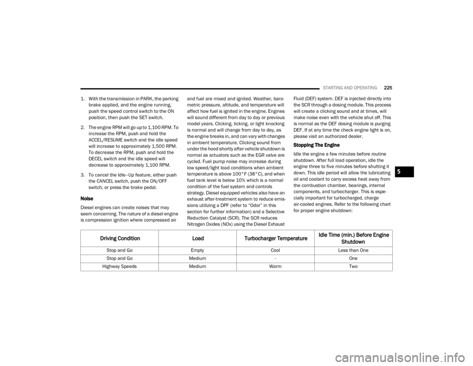
air-cooled engines. Refer to the following chart
for proper engine shutdown:
Driving Condition Load Turbocharger Temperature Idle Time (min.) Before Engine
Shutdown
Stop and Go EmptyCoolLess than One
Stop and Go Medium -One
Highway Speeds MediumWarmTwo
5
20_DJD2_OM_EN_USC_t.book Page 225
Page 230 of 553

228STARTING AND OPERATING
The block heater must be plugged in at least
one hour to have an adequate warming effect
on the coolant.
NOTE:
The block heater will require 110 Volts AC and
6.5 Amps to activate the heater element.
Block Heater Usage
For ambient temperatures below 0°F (-18°C),
engine block heater usage is recommended.
For ambient temperatures below –20°F
(-29°C), engine block heater usage is required.
ENGINE BREAK-IN RECOMMENDATIONS —
GAS ENGINE
A long break-in period is not required for the
engine and drivetrain (transmission and axle) in
your vehicle.
Drive moderately during the first 300 miles
(500 km). After the initial 60 miles (100 km), speeds up to 50 or 55 mph (80 or 90 km/h) are
desirable.
While cruising, brief full-throttle acceleration
within the limits of local traffic laws contributes
to a good break-in. Wide-open throttle accelera-
tion in low gear can be detrimental and should
be avoided.
The engine oil installed in the engine at the
factory is a high-quality energy conserving type
lubricant. Oil changes should be consistent with
anticipated climate conditions under which
vehicle operations will occur. For the recom
-
mended viscosity and quality grades, refer to
“Fluids And Lubricants” in “Technical Specifica-
tions”.
NOTE:
A new engine may consume some oil during its
first few thousand miles (kilometers) of opera -
tion. This should be considered a normal part of
the break-in and not interpreted as a problem.
Please check your oil level with the engine oil indicator often during the break in period. Add
oil as required.
ENGINE BREAK-IN RECOMMENDATIONS —
DIESEL ENGINE
The Cummins® Turbo Diesel engine does not
require a break-in period due to its construction.
Normal operation is allowed, providing the
following recommendations are followed:
Warm up the engine before placing it under
load.
Do not operate the engine at idle for
prolonged periods.
Use the appropriate transmission gear to
prevent engine lugging.
Observe vehicle oil pressure and tempera
-
ture indicators.
Check the coolant and oil levels frequently.
Vary throttle position at highway speeds
when carrying or towing significant weight.
WARNING!
Remember to disconnect the cord before
driving. Damage to the 110–115 Volt
electrical cord could cause electrocution.
CAUTION!
Never use Non-Detergent Oil or Straight
Mineral Oil in the engine or damage may
result.
20_DJD2_OM_EN_USC_t.book Page 228
Page 242 of 553
240STARTING AND OPERATING
engine may be started in this range. Apply the
parking brake and shift the transmission into
PARK if you must exit the vehicle.
DRIVE (D)
This range should be used for most city and
highway driving. It provides the smoothest
upshifts and downshifts, and the best fuel
economy. The transmission automatically
upshifts through underdrive first, second, and third gears, direct fourth gear and overdrive fifth
and sixth gears. The DRIVE position provides
optimum driving characteristics under all
normal operating conditions.
When frequent transmission shifting occurs
(such as when operating the vehicle under
heavy loading conditions, in hilly terrain, trav
-
eling into strong head winds, or while towing a
heavy trailer), use the Electronic Range Select
(ERS) shift control refer to “Electronic Range
Select (ERS) Operation” in this section for
further information to select a lower gear range.
Under these conditions, using a lower gear
range will improve performance and extend
transmission life by reducing excessive shifting
and heat buildup.
If the transmission temperature exceeds
normal operating limits, the powertrain
controller will modify the transmission shift
schedule and expand the range of torque
converter clutch engagement. This is done to
prevent transmission damage due to over -
heating.
If the transmission becomes extremely hot or is
in danger of overheating, the “Transmission
Temperature Warning Light” may illuminate and
the transmission may operate differently until
the transmission cools down. NOTE:
Use caution when operating a heavily loaded
vehicle at low speeds (such as towing a trailer
up a steep grade, or in stop-and-go traffic)
during hot weather. In these conditions, torque
converter slip can impose a significant addi
-
tional heat load on the cooling system. Down -
shifting the transmission to the lowest possible
gear (when climbing a grade), or shifting to
NEUTRAL (when stopped in heavy traffic) can
help to reduce this excess heat generation.
During cold temperatures, transmission opera -
tion may be modified depending on engine and
transmission temperature as well as vehicle
speed. This feature improves warm up time of
the engine and transmission to achieve
maximum efficiency. Engagement of the torque
converter clutch is inhibited until the transmis -
sion fluid is warm refer to the “Note” under
“Torque Converter Clutch” in this section. On
Pickup models with 68RFE transmission, top
overdrive gear is also inhibited until the trans -
mission fluid is warm, and during extremely cold
temperatures (-16°F [-27°C] or below), opera -
tion may briefly be limited to first and direct
gears only. On trucks with AS69RC transmis -
sion, fifth and sixth gears may be inhibited
briefly on cold starts below 41°F (5°C), and
WARNING!
Do not coast in NEUTRAL and never turn off
the ignition to coast down a hill. These are
unsafe practices that limit your response to
changing traffic or road conditions. You might
lose control of the vehicle and have a
collision.
CAUTION!
Towing the vehicle, coasting, or driving for any
other reason with the transmission in
NEUTRAL can cause severe transmission
damage. Refer to “Recreational Towing” in
“Starting And Operating” and “Towing A
Disabled Vehicle” in “In Case Of Emergency”
for further information.
20_DJD2_OM_EN_USC_t.book Page 240
Page 244 of 553

242STARTING AND OPERATING
To exit ERS mode, simply push and hold the ERS
(+) switch until the gear limit display disappears
from the instrument cluster.
NOTE:
To select the proper gear position for maximum
deceleration (engine braking), simply push and
hold the ERS (-) switch. The transmission will
shift to the range from which the vehicle can
best be slowed down.
Overdrive Operation
The automatic transmission includes an elec -
tronically controlled Overdrive (fifth and sixth
gears). The transmission will automatically shift
into Overdrive if the following conditions are
present:
The gear selector is in the DRIVE position.
The transmission fluid has reached an
adequate temperature.
The engine coolant has reached an adequate
temperature.
The vehicle speed is sufficiently high.
The driver is not heavily pressing the acceler -
ator.
When To Use TOW/HAUL Mode
When driving in hilly areas, towing a trailer,
carrying a heavy load, etc., and frequent trans -
mission shifting occurs, push the TOW/HAUL switch to activate TOW/HAUL mode. This will
improve performance and reduce the potential
for transmission overheating or failure due to
excessive shifting. When operating in TOW/
HAUL mode, transmission upshifts are delayed,
and the transmission will automatically down
-
shift (for engine braking) when the throttle is
closed and/or during steady braking maneu -
vers.
TOW/HAUL Switch
The “TOW/HAUL Indicator Light” will illuminate
in the instrument cluster to indicate that TOW/
HAUL mode has been activated. Pushing the
switch a second time restores normal opera -
tion. Normal operation is always the default at
engine start-up. If TOW/HAUL mode is desired,
the switch must be pushed each time the
engine is started.
WARNING!
Do not downshift for additional engine
braking on a slippery surface. The drive
wheels could lose their grip and the vehicle
could skid, causing a collision or personal
injury.
Transmis -
sion Gear
Limit Dis -
play 1 2 3 4 5 6 D
Actual
Gear(s)
Allowed
1 1-2 1-3 1-4 1-5 1-6 1-6
CAUTION!
When using ERS for engine braking while
descending steep grades, be careful not to
overspeed the engine. Apply the brakes as
needed to prevent engine overspeed.
20_DJD2_OM_EN_USC_t.book Page 242