turn signal Ram 2500 2020 Owner's Manual
[x] Cancel search | Manufacturer: RAM, Model Year: 2020, Model line: 2500, Model: Ram 2500 2020Pages: 553, PDF Size: 21.99 MB
Page 5 of 553

3
Power Mirrors — If Equipped ...................... 45
Power Convex Mirror Switch —
If Equipped ................................................... 46 Trailer Towing Mirrors — If Equipped ......... 46
Heated Mirrors — If Equipped ..................... 47
Tilt Side Mirrors In Reverse —
If Equipped ................................................... 47 Power Folding Outside Mirrors For
Standard And Trailer Tow — If Equipped .... 47 Illuminated Vanity Mirror — If Equipped ..... 48
EXTERIOR LIGHTS.................................................49
Multifunction Lever ...................................... 49
Headlight Switch .......................................... 49
Daytime Running Lights (DRLs) —
If Equipped ................................................... 49 High/Low Beam Switch ............................... 50
Automatic High Beam Headlamp Control —
If Equipped ................................................... 50 Flash-To-Pass ............................................... 51
Automatic Headlights — If Equipped ......... 51
Directional LED Headlamp System — If
Equipped ...................................................... 51 Parking Lights And Panel Lights ................. 51
Headlights On With Wipers (Available With
Automatic Headlights Only) ......................... 51 Headlight Delay ............................................ 51
Lights-On Reminder ..................................... 52 Front Fog Lights — If Equipped .................. 52
Turn Signals ................................................ 52
Lane Change Assist — If Equipped ............. 52
Cargo Lights/Trailer Spotter Lights With
Bed Lights — If Equipped............................. 52 Battery Saver ............................................... 53
INTERIOR LIGHTS ................................................ 53
Courtesy Lights ............................................ 53
Illuminated Entry ......................................... 55
WINDSHIELD WIPERS AND WASHERS............. 55
Windshield Wipers ....................................... 55
Rain Sensing Wipers — If Equipped ........... 56
CLIMATE CONTROLS ........................................... 57
Manual Climate Control Overview .............. 57
Automatic Climate Control Overview .......... 61
Climate Control Functions........................... 68
Automatic Temperature Control (ATC) ....... 68
Operating Tips ............................................. 69
WINDOWS ............................................................ 70
Power Windows ........................................... 70
Wind Buffeting ............................................ 72
POWER SUNROOF — IF EQUIPPED .................... 72
Single Pane Power Sunroof —
If Equipped ................................................... 72
HOOD .................................................................... 74
To Open The Hood ...................................... 74
To Close The Hood ....................................... 75 TAILGATE ...............................................................75
Opening ........................................................ 75
Closing.......................................................... 75
Bed Step — If Equipped ............................... 75
GARAGE DOOR OPENER — IF EQUIPPED ..........76
Before You Begin Programming
HomeLink® .................................................. 77 Canadian/Gate Operator Programming..... 79
Using HomeLink®........................................ 80
Security ........................................................ 80
Troubleshooting Tips ................................... 80
General Information .................................... 81
INTERNAL EQUIPMENT ........................................82
Storage ......................................................... 82
Cupholders .................................................. 87
Electrical Power Outlets .............................. 88
Power Inverter — If Equipped ..................... 90
Wireless Charging Pad — If Equipped ....... 91
Overhead Sunglass Storage ....................... 92
PICKUP BOX .........................................................92
Cargo Camera — If Equipped ...................... 93
RAMBOX — IF EQUIPPED .....................................94
RamBox Integrated Box Side Storage
Bins............................................................... 95 RamBox Safety Warning ............................. 96
Bed Divider — If Equipped ........................... 96
Bed Rail Tie-Down System —
If Equipped .................................................. 98
20_DJD2_OM_EN_USC_t.book Page 3
Page 16 of 553
14GETTING TO KNOW YOUR VEHICLE
TIP:
When viewing a topic, tap the star icon to add it
to your Favorites, for easy access in the future.
KEYS
Key Fob
Your vehicle uses a keyless ignition system. The
ignition system consists of a key fob and a
START/STOP push button ignition system. The
Remote Keyless Entry (RKE) system consists of
a key fob and Keyless Enter-N-Go feature.
NOTE:
The key fob may not be found if it is located next
to a mobile phone, laptop or other electronic
device; these devices may block the key fob’s
wireless signal.
The key fob allows you to lock or unlock all
doors, tailgate, and the RamBox (if equipped),
as well as release the tailgate, and activate the
Panic Alarm from distances up to approximately
66 ft (20 m). The key fob does not need to be
pointed at the vehicle to activate the system. NOTE:
In the ON/RUN position, all key fob buttons
will work until the vehicle reaches 2 mph
(4 km/h).
The key fob should not be placed next to the
wireless charging pad (if equipped).
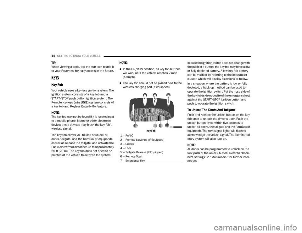
Key Fob
In case the ignition switch does not change with
the push of a button, the key fob may have a low
or fully depleted battery. A low key fob battery
can be verified by referring to the instrument
cluster, which will display directions to follow.
In a situation where the battery is low or fully
depleted, a back up method can be used to
operate the ignition switch. Put the nose side of
the key fob (side opposite of the emergency key)
against the START/STOP ignition button and
push to operate the ignition switch.
To Unlock The Doors And Tailgate
Push and release the unlock button on the key
fob once to unlock the driver’s door. Push the
unlock button twice within five seconds to
unlock all doors, the tailgate and the RamBox (if
equipped). The turn signal lights will flash to
acknowledge the unlock signal. The illuminated
entry system will also turn on.
NOTE:
All doors can be programmed to unlock on the
first push of the unlock button. Refer to “Ucon
-
nect Settings” in “Multimedia” for further infor -
mation.
1 — PANIC
2 — Remote Lowering (If Equipped)
3 — Unlock
4 — Lock
5 — Tailgate Release (If Equipped)
6 — Remote Start
7 — Emergency Key
20_DJD2_OM_EN_USC_t.book Page 14
Page 17 of 553
GETTING TO KNOW YOUR VEHICLE15
To Lock The Doors And Tailgate
Push and release the lock button on the key fob
to lock all doors, the tailgate, and the RamBox
(if equipped). The turn signal lights will flash and
the horn will chirp to acknowledge the signal.
Sound Horn With Remote Key Lock — If
Equipped
This feature will cause the horn to chirp when
the doors are locked with the key fob. This
feature can be turned on or turned off through
the Uconnect settings.
NOTE:
Pushing the lock button on the key fob while you
are in the vehicle will activate the vehicle secu -
rity alarm system. Opening a door with the
vehicle security alarm system activated will
cause the alarm to sound. Push the unlock
button to deactivate the vehicle security alarm
system.
Refer to “Vehicle Security Alarm” in this chapter
for further information.
Using The Panic Alarm
To turn the Panic Alarm feature on or off, push
the Panic button on the key fob. When the Panic
Alarm is activated, the turn signals will flash, the horn will pulse on and off, and the interior lights
will turn on.
The Panic Alarm will stay on for three minutes
unless you turn it off by either pushing the Panic
button a second time or drive the vehicle at a
speed of 15 mph (24 km/h) or greater.
NOTE:
The interior lights will turn off if you place the
ignition in the ACC or ON/RUN position while
the Panic Alarm is activated. However, the
exterior lights and horn will remain on.
You may need to be less than 35 ft (11 m)
from the vehicle when using the key fob to
turn off the Panic Alarm due to the radio
frequency noises emitted by the system.
Replacing The Battery In The Key Fob With
Remote Control
The replacement battery model is one CR2032
battery.
NOTE:
Perchlorate Material — special handling may
apply. See
www.dtsc.ca.gov/hazard -
ouswaste/perchlorate for further
information.
Do not touch the battery terminals that are
on the back housing or the printed circuit
board.
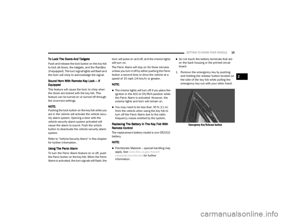
1. Remove the emergency key by pushing and holding the release button located on
the side of the key fob while pulling the
emergency key out with your other hand.
Emergency Key Release button
2
20_DJD2_OM_EN_USC_t.book Page 15
Page 52 of 553
50GETTING TO KNOW YOUR VEHICLE
Lights (DRLs) will turn off. Also, if a turn signal is
activated, the DRL lamp on the same side of the
vehicle may turn off for the duration of the turn
signal activation. Once the turn signal is no
longer active, the DRL lamp will illuminate.
NOTE:
If allowed by law in the country in which the
vehicle was purchased, the Daytime Running
Lights can be turned on and off using the Ucon -
nect System, refer to “Uconnect Settings” in
“Multimedia” for further information.
High/Low Beam Switch
Push the multifunction lever toward the instru-
ment panel to switch the headlights to high
beam. Pulling the multifunction lever back
toward the steering wheel will turn the low
beams back on, or shut the high beams off.
Automatic High Beam Headlamp Control —
If Equipped
The Automatic High Beam Headlamp Control
system provides increased forward lighting at
night by automating high beam control through
the use of a digital camera mounted on the
inside rearview mirror or forward facing camera.
This camera detects vehicle specific light and automatically switches from high beams to low
beams until the approaching vehicle is out of
view.
NOTE:
The Automatic High Beam Headlamp Control
can be turned on or off by selecting “ON”
under “Auto Dim High Beams” within your
Uconnect settings, as well as turning the
headlight switch to the AUTO position. Refer
to “Uconnect Settings” in “Multimedia” for
further information.
Broken, muddy, or obstructed headlights and
taillights of vehicles in the field of view will
cause headlights to remain on longer (closer
to the vehicle). Also, dirt, film, and other
obstructions on the windshield or camera
lens will cause the system to function improp
-
erly.
To opt out of the Advanced Auto High Beam
Sensitivity Control (default) and enter
Reduced High Beam Sensitivity Control (not
recommended), on vehicles equipped with
mirror controlled automatic high beams and
without the forward facing camera, toggle the
high beam lever six full on/off cycles within 10 seconds of placing the ignition in the ON
position. The system will return to the default
setting when the ignition is OFF.
If the windshield or Automatic High Beam Head -
lamp Control mirror is replaced, the mirror must
be re-aimed to ensure proper performance. See
a local authorized dealer.
To Activate
1. The Automatic High Beams are enabled through the Uconnect system. Refer to
“Uconnect Settings” in “Multimedia” for
further information.
2. Turn the headlight switch to the AUTO head -
light position.
3. Push the multifunction lever away from you (toward front of vehicle) to engage the high
beam mode.
NOTE:
The Automatic High Beams will not activate until
the vehicle is at or above 12 mph (20 km/h).
20_DJD2_OM_EN_USC_t.book Page 50
Page 53 of 553
GETTING TO KNOW YOUR VEHICLE51
To Deactivate
1. Pull the multifunction lever toward you (or
rearward in vehicle) to manually deactivate
the system (normal operation of low
beams).
2. Push back on the multifunction lever to reactivate the system.
The Automatic High Beams can also be deacti -
vated through the Uconnect system. Refer to
“Uconnect Settings” in “Multimedia” for further
information.
Flash-To-Pass
You can signal another vehicle with your head -
lights by lightly pulling the multifunction lever
toward you. This will cause the high beam head -
lights to turn on, and remain on, until the lever
is released.
Automatic Headlights — If Equipped
This system automatically turns your headlights
on or off based on ambient light levels. To turn
the system on, turn the headlight switch to the
extreme clockwise position aligning the indi -
cator with the AUTO on the headlight switch.
When the system is on, the Headlight Time
Delay feature is also on. This means your head -lights will stay on for up to 90 seconds after the
ignition is placed in the OFF position. To turn the
Automatic System off, turn the headlight switch
counterclockwise to the O (off) position.
NOTE:
The engine must be running before the head
-
lights will come on in the Automatic mode.
Directional LED Headlamp System — If
Equipped
This is a system consisting of LED (low/high
beam) headlights that incorporate dynamic
cornering with 5-degree inboard/15-degree
outboard swivel. The headlights continuously
and automatically adapt to the driving condi -
tions around bends or when cornering based on
steering wheel angle.
The system directs the headlights to light up the
road in the best way, taking into account the
speed of the vehicle and the bend or corner
angle, as well as the speed of the vehicle while
the steering wheel is being turned.
The adaptive lights are automatically activated
when the vehicle is traveling above approxi -
mately 5 mph (8 km/h).
This system can be turned on/off through the
Uconnect settings under “Steering Directed Lights”. Refer to Uconnect Settings in “Multi
-
media” for further information.
Parking Lights And Panel Lights
To turn on the parking lights and instrument
panel lights, from the O (off) position, rotate the
headlight switch clockwise to the first detent. To
turn off the parking lights, rotate the headlight
switch back to the O (off) position.
Headlights On With Wipers (Available With
Automatic Headlights Only)
When this feature is active, the headlights will
turn on approximately 10 seconds after the
wipers are turned on if the headlight switch is
placed in the AUTO position. In addition, the
headlights will turn off when the wipers are
turned off, if they were turned on by this feature.
NOTE:
This feature can be programmed through the
Uconnect system. Refer to “Uconnect Settings”
in “Multimedia” for further information.
Headlight Delay
To aid in your exit, your vehicle is equipped with
a headlight delay that will leave the headlights
on for up to 90 seconds. This delay is initiated
when the ignition is turned off while the head -
2
20_DJD2_OM_EN_USC_t.book Page 51
Page 54 of 553
52GETTING TO KNOW YOUR VEHICLE
light switch is on, and then the headlight switch
is cycled off. Headlight delay can be canceled by
either turning the headlight switch on then off,
or by placing the ignition in the ON/RUN posi -
tion.
NOTE:
This feature can be programmed through the
Uconnect system. Refer to “Uconnect Settings”
in “Multimedia” for further information.
Lights-On Reminder
If the headlights, parking lights, or cargo lights
are left on after the ignition is placed in the OFF
position, a chime will sound and a message will
appear in the instrument cluster display when
the driver’s door is opened.
Front Fog Lights — If Equipped
To activate the front fog lights, turn on the
parking lights or low beam headlights and push
in the center of the headlight switch control
knob. Pushing the headlight switch control knob
a second time will turn the front fog lights off.
Front Fog Light Switch
Turn Signals
Move the multifunction lever up or down and
the arrows on each side of the instrument
cluster display will flash to show proper opera
-
tion of the front and rear turn signal lights.
NOTE:
If either light remains on and does not flash, or
there is a very fast flash rate, check for a defec -
tive outside light bulb. If an indicator fails to
light when the lever is moved, it would suggest
that the indicator bulb is defective.
Lane Change Assist — If Equipped
Tap the multifunction lever up or down once,
without moving beyond the detent, and the turn signal (right or left) will flash three times then
automatically turn off.
Cargo Lights/Trailer Spotter Lights With Bed
Lights — If Equipped
The cargo light and bed lights (if equipped) and
trailer spotter lights (if equipped) are turned on
by pushing the cargo lights button located on
the lower half of the headlight switch.
Cargo/Bed Lights Button On Headlight Switch
If the vehicle’s speed is 0 mph (0 km/h), these
lights can also be turned on using the switch
located just inside the pickup box, on the lower
part of the bed light lens. A telltale will illumi -
nate in the instrument cluster display when
these lights are on. Pushing the switch a second
time will turn the lights off.
20_DJD2_OM_EN_USC_t.book Page 52
Page 80 of 553
78GETTING TO KNOW YOUR VEHICLE
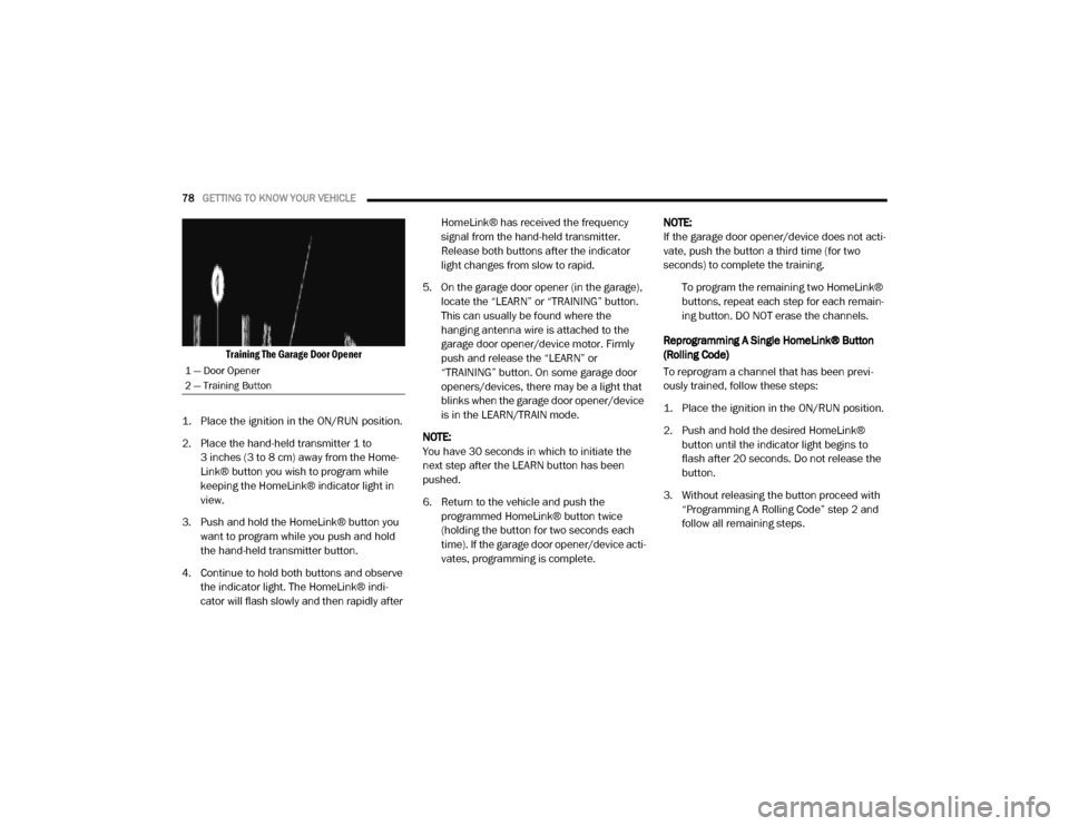
Training The Garage Door Opener
1. Place the ignition in the ON/RUN position.
2. Place the hand-held transmitter 1 to 3 inches (3 to 8 cm) away from the Home-
Link® button you wish to program while
keeping the HomeLink® indicator light in
view.
3. Push and hold the HomeLink® button you want to program while you push and hold
the hand-held transmitter button.
4. Continue to hold both buttons and observe the indicator light. The HomeLink® indi-
cator will flash slowly and then rapidly after HomeLink® has received the frequency
signal from the hand-held transmitter.
Release both buttons after the indicator
light changes from slow to rapid.
5. On the garage door opener (in the garage), locate the “LEARN” or “TRAINING” button.
This can usually be found where the
hanging antenna wire is attached to the
garage door opener/device motor. Firmly
push and release the “LEARN” or
“TRAINING” button. On some garage door
openers/devices, there may be a light that
blinks when the garage door opener/device
is in the LEARN/TRAIN mode.
NOTE:
You have 30 seconds in which to initiate the
next step after the LEARN button has been
pushed.
6. Return to the vehicle and push the programmed HomeLink® button twice
(holding the button for two seconds each
time). If the garage door opener/device acti -
vates, programming is complete. NOTE:
If the garage door opener/device does not acti
-
vate, push the button a third time (for two
seconds) to complete the training.
To program the remaining two HomeLink®
buttons, repeat each step for each remain -
ing button. DO NOT erase the channels.
Reprogramming A Single HomeLink® Button
(Rolling Code)
To reprogram a channel that has been previ -
ously trained, follow these steps:
1. Place the ignition in the ON/RUN position.
2. Push and hold the desired HomeLink® button until the indicator light begins to
flash after 20 seconds. Do not release the
button.
3. Without releasing the button proceed with “Programming A Rolling Code” step 2 and
follow all remaining steps.
1 — Door Opener
2 — Training Button
20_DJD2_OM_EN_USC_t.book Page 78
Page 132 of 553
130GETTING TO KNOW YOUR INSTRUMENT PANEL
After a trip:
Check if any aftermarket equipment was
installed (additional lights, upfitter electrical
accessories, audio systems, alarms) and
review specifications if any (load and Ignition
Off Draw currents).
Evaluate the latest driving cycles (distance,
driving time and parking time).
The vehicle should have service performed if
the message is still present during consecu-
tive trips and the evaluation of the vehicle
and driving pattern did not help to identify the
cause.
WARNING LIGHTS AND MESSAGES
The warning/indicator lights will illuminate in
the instrument panel together with a dedicated
message and/or acoustic signal when appli -
cable. These indications are indicative and
precautionary and as such must not be consid -
ered as exhaustive. Always refer to the informa-
tion in this chapter in the event of a failure
indication. All active telltales will display first if
applicable. The system check menu may
appear different based upon equipment
options and current vehicle status. Some tell -
tales are optional and may not appear.
Red Warning Lights
Seat Belt Reminder Warning Light
This warning light indicates when the
driver or passenger seat belt is
unbuckled. When the ignition is first
placed in the ON/RUN or ACC/ON/
RUN position and if the driver’s seat belt is
unbuckled, a chime will sound and the light will
turn on. When driving, if the driver or front
passenger seat belt remains unbuckled, the
Seat Belt Reminder Light will flash or remain on
continuously and a chime will sound.
Refer to “Occupant Restraint Systems” in
“Safety” for further information.
Air Bag Warning Light
This warning light will illuminate to
indicate a fault with the air bag, and
will turn on for four to eight seconds
as a bulb check when the ignition is
placed in the ON/RUN or ACC/ON/RUN posi -
tion. This light will illuminate with a single chime
when a fault with the air bag has been detected,
it will stay on until the fault is cleared. If the light
is either not on during startup, stays on, or turns
on while driving, have the system inspected at
an authorized dealer as soon as possible.
Brake Warning Light
This warning light monitors various
brake functions, including brake fluid
level and parking brake application. If
the brake light turns on it may indi -
cate that the parking brake is applied, that the
brake fluid level is low, or that there is a
problem with the anti-lock brake system reser -
voir.
If the light remains on when the parking brake
has been disengaged, and the fluid level is at
the full mark on the master cylinder reservoir, it
indicates a possible brake hydraulic system
malfunction or that a problem with the Brake
Booster has been detected by the Anti-Lock
Brake System (ABS) / Electronic Stability
Control (ESC) system. In this case, the light will
remain on until the condition has been
corrected. If the problem is related to the brake
booster, the ABS pump will run when applying
the brake, and a brake pedal pulsation may be
felt during each stop.
The dual brake system provides a reserve
braking capacity in the event of a failure to a
portion of the hydraulic system. A leak in either
half of the dual brake system is indicated by the
Brake Warning Light, which will turn on when
20_DJD2_OM_EN_USC_t.book Page 130
Page 136 of 553
134GETTING TO KNOW YOUR INSTRUMENT PANEL
Electronic Stability Control (ESC) Active
Warning Light — If Equipped
This warning light will indicate when
the Electronic Stability Control system
is Active. The “ESC Indicator Light” in
the instrument cluster will come on
when the ignition is placed in the ON/RUN or ACC/ON/RUN position, and when ESC is acti
-
vated. It should go out with the engine running.
If the “ESC Indicator Light” comes on continu -
ously with the engine running, a malfunction
has been detected in the ESC system. If this
warning light remains on after several ignition
cycles, and the vehicle has been driven several
miles (kilometers) at speeds greater than
30 mph (48 km/h), see an authorized dealer as
soon as possible to have the problem diag -
nosed and corrected.
The “ESC OFF Indicator Light” and the “ESC
Indicator Light” come on momentarily each
time the ignition is placed in the ON/RUN or
ACC/ON/RUN position.
The ESC system will make buzzing or clicking
sounds when it is active. This is normal; the
sounds will stop when ESC becomes inactive.
This light will come on when the vehicle is in
an ESC event.
Electronic Stability Control (ESC) OFF
Warning Light — If Equipped
This warning light indicates the Elec -
tronic Stability Control (ESC) is off.
Each time the ignition is turned to ON/
RUN or ACC/ON/RUN, the ESC system
will be on, even if it was turned off previously.
LaneSense Warning Light — If Equipped
The LaneSense system provides the
driver with visual and steering torque
warnings when the vehicle starts to
drift out of its lane unintentionally
without the use of a turn signal.
When the LaneSense system senses a lane
drift situation, the LaneSense indicator
changes from solid green to solid yellow.
When the LaneSense system senses the lane
has been approached and is in a lane depar -
ture situation, the LaneSense indicator
changes from solid white/green to flashing
yellow.
Refer to “LaneSense – If Equipped” in
“Starting And Operating” for further informa -
tion.
WARNING!
A malfunctioning catalytic converter, as
referenced above, can reach higher
temperatures than in normal operating
conditions. This can cause a fire if you drive
slowly or park over flammable substances
such as dry plants, wood, cardboard, etc. This
could result in death or serious injury to the
driver, occupants or others.
CAUTION!
Prolonged driving with the Malfunction
Indicator Light (MIL) on could cause damage
to the vehicle control system. It also could
affect fuel economy and driveability. If the
MIL is flashing, severe catalytic converter
damage and power loss will soon occur.
Immediate service is required.
20_DJD2_OM_EN_USC_t.book Page 134
Page 138 of 553
136GETTING TO KNOW YOUR INSTRUMENT PANEL
tire causes the tire to overheat and can lead to
tire failure. Under-inflation also reduces fuel
efficiency and tire tread life, and may affect the
vehicle’s handling and stopping ability.
Please note that the TPMS is not a substitute for
proper tire maintenance, and it is the driver’s
responsibility to maintain correct tire pressure,
even if under-inflation has not reached the level
to trigger illumination of the TPMS low tire pres-
sure telltale.
Your vehicle has also been equipped with a
TPMS malfunction indicator to indicate when
the system is not operating properly. The TPMS
malfunction indicator is combined with the low
tire pressure telltale. When the system detects
a malfunction, the telltale will flash for approxi -
mately one minute and then remain continu -
ously illuminated. This sequence will continue
upon subsequent vehicle start-ups as long as
the malfunction exists. When the malfunction
indicator is illuminated, the system may not be
able to detect or signal low tire pressure as
intended. TPMS malfunctions may occur for a
variety of reasons, including the installation of
replacement or alternate tires or wheels on the
vehicle that prevent the TPMS from functioning
properly. Always check the TPMS malfunction
telltale after replacing one or more tires or wheels on your vehicle to ensure that the
replacement or alternate tires and wheels allow
the TPMS to continue to function properly.
Anti-Lock Brake (ABS) Warning Light
This warning light monitors the
Anti-Lock Brake System (ABS). The
light will turn on when the ignition is
placed in the ON/RUN or ACC/ON/RUN position
and may stay on for as long as four seconds.
If the ABS light remains on or turns on while
driving, then the Anti-Lock portion of the brake
system is not functioning and service is
required as soon as possible. However, the
conventional brake system will continue to
operate normally, assuming the Brake Warning
Light is not also on.
If the ABS light does not turn on when the igni
-
tion is placed in the ON/RUN or ACC/ON/RUN
position, have the brake system inspected by an
authorized dealer.
Rear Axle Locker Fault Indicator Light — If
Equipped
This warning light will illuminate to
indicate when a rear axle locker fault
has been detected.
Refer to “Axle Locker System — Power
Wagon Models Only (If Equipped)” in “Starting
And Operating” for further information.
CAUTION!
The TPMS has been optimized for the original
equipment tires and wheels. TPMS pressures
and warning have been established for the
tire size equipped on your vehicle.
Undesirable system operation or sensor
damage may result when using replacement
equipment that is not of the same size, type,
and/or style. Aftermarket wheels can cause
sensor damage. Using aftermarket tire
sealants may cause the Tire Pressure
Monitoring System (TPMS) sensor to become
inoperable. After using an aftermarket tire
sealant it is recommended that you take your
vehicle to an authorized dealer to have your
sensor function checked.
20_DJD2_OM_EN_USC_t.book Page 136