width Ram 2500 2020 Owner's Manual
[x] Cancel search | Manufacturer: RAM, Model Year: 2020, Model line: 2500, Model: Ram 2500 2020Pages: 553, PDF Size: 21.99 MB
Page 35 of 553
GETTING TO KNOW YOUR VEHICLE33
(Continued)
Manual Front Seat Recline Adjustment
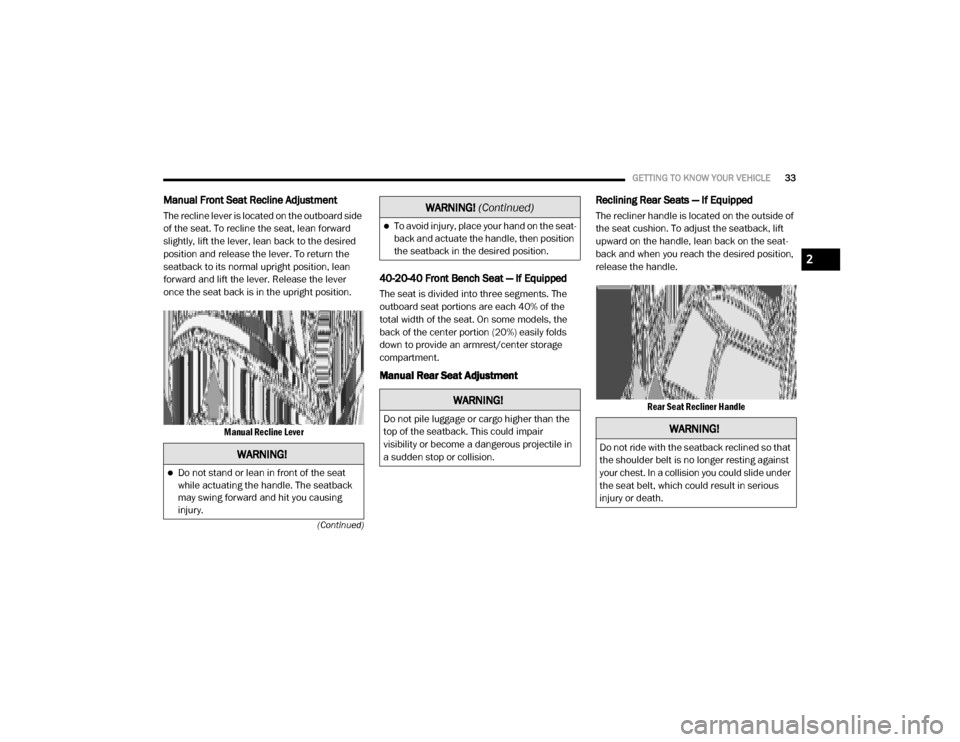
The recline lever is located on the outboard side
of the seat. To recline the seat, lean forward
slightly, lift the lever, lean back to the desired
position and release the lever. To return the
seatback to its normal upright position, lean
forward and lift the lever. Release the lever
once the seat back is in the upright position.
Manual Recline Lever
40-20-40 Front Bench Seat — If Equipped
The seat is divided into three segments. The
outboard seat portions are each 40% of the
total width of the seat. On some models, the
back of the center portion (20%) easily folds
down to provide an armrest/center storage
compartment.
Manual Rear Seat Adjustment Reclining Rear Seats — If Equipped
The recliner handle is located on the outside of
the seat cushion. To adjust the seatback, lift
upward on the handle, lean back on the seat
-
back and when you reach the desired position,
release the handle.
Rear Seat Recliner Handle
WARNING!
Do not stand or lean in front of the seat
while actuating the handle. The seatback
may swing forward and hit you causing
injury.
To avoid injury, place your hand on the seat -
back and actuate the handle, then position
the seatback in the desired position.
WARNING!
Do not pile luggage or cargo higher than the
top of the seatback. This could impair
visibility or become a dangerous projectile in
a sudden stop or collision.
WARNING! (Continued)
WARNING!
Do not ride with the seatback reclined so that
the shoulder belt is no longer resting against
your chest. In a collision you could slide under
the seat belt, which could result in serious
injury or death.
2
20_DJD2_OM_EN_USC_t.book Page 33
Page 155 of 553
SAFETY153
Traction Control System (TCS)
This system monitors the amount of wheel spin
of each of the driven wheels. If wheel spin is
detected, the Traction Control System (TCS)
may apply brake pressure to the spinning
wheel(s) and/or reduce engine power to provide
enhanced acceleration and stability. A feature
of the TCS, Brake Limited Differential (BLD),
functions similar to a limited slip differential
and controls the wheel spin across a driven
axle. If one wheel on a driven axle is spinning
faster than the other, the system will apply the
brake of the spinning wheel. This will allow more
engine power to be applied to the wheel that is
not spinning. BLD may remain enabled even if
TCS and Electronic Stability Control (ESC) are in
a reduced mode.
Trailer Sway Control (TSC)
Trailer Sway Control (TSC) uses sensors in the
vehicle to recognize an excessively swaying
trailer and will take the appropriate actions to
attempt to stop the sway. TSC will become
active automatically once an excessively
swaying trailer is recognized. NOTE:
TSC cannot stop all trailers from swaying.
Always use caution when towing a trailer and
follow the trailer tongue weight recommenda
-
tions. Refer to “Trailer Towing” in “Starting And
Operating” for further information.
When TSC is functioning, the “ESC Activation/
Malfunction Indicator Light” will flash, the
engine power may be reduced and you may feel
the brakes being applied to individual wheels to
attempt to stop the trailer from swaying. TSC is
disabled when the ESC system is in the “Partial
Off” or “Full Off” modes.
AUXILIARY DRIVING SYSTEMS
Blind Spot Monitoring (BSM) — If Equipped
The Blind Spot Monitoring (BSM) system uses
two radar-based sensors, located inside the tail -
lights, to detect highway licensable vehicles
(automobiles, trucks, motorcycles, etc.) that enter the blind spot zones from the rear/front/
side of the vehicle.
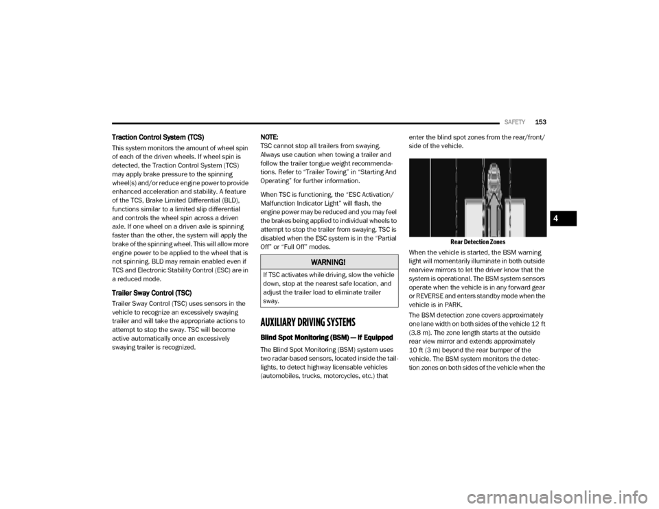
Rear Detection Zones
When the vehicle is started, the BSM warning
light will momentarily illuminate in both outside
rearview mirrors to let the driver know that the
system is operational. The BSM system sensors
operate when the vehicle is in any forward gear
or REVERSE and enters standby mode when the
vehicle is in PARK.
The BSM detection zone covers approximately
one lane width on both sides of the vehicle 12 ft
(3.8 m). The zone length starts at the outside
rear view mirror and extends approximately
10 ft (3 m) beyond the rear bumper of the
vehicle. The BSM system monitors the detec -
tion zones on both sides of the vehicle when the
WARNING!
If TSC activates while driving, slow the vehicle
down, stop at the nearest safe location, and
adjust the trailer load to eliminate trailer
sway.
4
20_DJD2_OM_EN_USC_t.book Page 153
Page 160 of 553

158SAFETY
Blind Spot Zones With Trailer Merge Assist
Automatic Trailer Detection
There are two modes of operation for the detec -
tion of the trailer length:
Automatic Mode — When “Auto Mode” is
selected, the system will use the blind spot
sensors to automatically determine the pres -
ence and length of a trailer. The presence of
a trailer will be detected using the blind spot
radar within 90 seconds of forward move -
ment of the vehicle. The vehicle must be
moving above 6 mph (10 km/h) to activate
the feature. Once the trailer has been
detected, the system will default to the
maximum blind spot zone until the length has been verified. You will see “Auto” in the
instrument panel cluster .
Max Mode
— When “Max Mode” is selected,
the system will default to the maximum blind
spot zone regardless of what size trailer is
attached .
NOTE:
Selected setting is stored when the ignition is
placed in the OFF position. To change this
setting, it must be selected through the Ucon -
nect Settings. Refer to “Uconnect Settings” in
“Multimedia” for further information.
Trailer Length Detection
Once the trailer presence has been established,
the trailer length will be established (by making
a 90 degree turn) and then the trailer length
category (e.g. 10-20 ft (3 m to 6 m)) will be
displayed. This can take up to 30 seconds after
completing the turn.
NOTE:
During the same ignition cycle, if the vehicle is
at a standstill for a minimum of 90 seconds, a
new “trailer detection request” is enabled by
the system once the vehicle resumes motion. Maximum length supported by the Trailer Merge
Assist feature is 39.5 ft (12 m). Trailer length is
considered the forward most portion of the
trailer hitch to the rearward most portion of the
body, bumper, or ramp of the trailer.
Maximum width supported by the Trailer Merge
Assist feature is 8.5 ft (2.59 m). Trailer width is
measured at the widest portion of the trailer
and may include wheels, tires, finders, or rails.
NOTE:
Fifth wheel or gooseneck trailers are not
supported by Trailer Merge Assist.
Trailer Length Detection
1 — Vehicle
2 — Trailer
1 — Trailer Length
2 — Trailer Width
3 — Trailer Hitch
20_DJD2_OM_EN_USC_t.book Page 158
Page 305 of 553
STARTING AND OPERATING303
image will continue to be displayed until the
display timer exceeds 10 seconds.
NOTE:
If the vehicle speed remains below 8 mph
(13 km/h), the Rear View Camera image will
be displayed continuously until deactivated
via the touchscreen button "X", the transmis -
sion is shifted into PARK, or the ignition is
placed in the OFF position.
The touchscreen button "X" to disable display
of the camera image is made available ONLY
when the vehicle is not in REVERSE.
Cargo Camera Icons — If Equipped Backup Camera Touchscreen Button
Cargo Camera Touchscreen Button
AUX Camera Touchscreen Button
If equipped with a Cargo Camera, a touchscreen
button to indicate the current active Camera
image being displayed is made available when -
ever the Rear View Camera image is displayed. If equipped with a Cargo Camera, a touchscreen
button to switch the display to Cargo Camera
image is made available whenever the Rear
View Camera image is displayed.
A touchscreen button "X" to disable display of
the camera image is made available when the
vehicle is not in REVERSE gear.
When enabled, active guidelines are overlaid on
the backup camera image to illustrate the width
of the vehicle and its projected backup path
based on the steering wheel position. The active
guidelines will show separate zones that will
help indicate the distance to the rear of the
vehicle.
NOTE:
For further information about how to access
and change the programmable features of the
ParkView Rear Backup Camera, refer to “Ucon
-
nect Settings” in “Multimedia.”
A dashed center line overlay indicates the
center of the vehicle to assist with parking or
aligning to a hitch/receiver. The following table
shows the approximate distances for each
zone:
Zones Distance To The Rear
Of The Vehicle
Red 0 - 1 ft (0 - 30 cm)
Yellow 1 ft - 6.5 ft
(30 cm - 2m)
Green 6.5 ft or greater
(2 m or greater)
WARNING!
Drivers must be careful when backing up
even when using the ParkView Rear Back Up
Camera. Always check carefully behind your
vehicle, and be sure to check for pedestrians,
animals, other vehicles, obstructions, or blind
spots before backing up. You are responsible
for the safety of your surroundings and must
continue to pay attention while backing up.
Failure to do so can result in serious injury or
death.5
20_DJD2_OM_EN_USC_t.book Page 303
Page 307 of 553
STARTING AND OPERATING305
Deactivation
The AUX Camera is deactivated by pressing the
“X” in the upper right corner of the touchscreen.
This will return the display back to the previ -
ously displayed screen.
NOTE:
If the AUX button is pressed and no AUX
Camera is connected, the touchscreen will
display a blue screen along with the message
“Camera System Unavailable.” The screen
can be exited out by pressing the “X” in the
upper right hand corner. This will return the
display back to the previously displayed
screen.
Zoom View is not available with the AUX
Camera feature.
The display will always default to the Trailer
Camera display (AUX 1).
SURROUND VIEW CAMERA SYSTEM — IF
EQUIPPED
Your vehicle may be equipped with the
Surround View Camera System that allows you
to see an on-screen image of the surroundings
and top view of your vehicle whenever the gear selector is put into REVERSE or manually acti
-
vated via the Uconnect system. The top view of
the vehicle will show which doors are open. The
image will be displayed on the touchscreen
display along with a caution note “Check Entire
Surroundings” across the top of the screen.
After five seconds, this note will disappear. The
Surround View Camera System is comprised of
four sequential cameras located in the front
grille, rear tailgate and side mirrors.
NOTE:
The Surround View Camera System has
programmable settings that may be selected
through the Uconnect System. Refer to “Ucon -
nect Settings” in “Multimedia” for further infor -
mation.
When the vehicle is shifted into REVERSE, the
rear camera view and top view is the default
view of the system (Automatic Activation).
When the vehicle is shifted out of REVERSE
(with camera delay turned on), the camera
image will continue to be displayed for up to 10
seconds after shifting out of REVERSE unless
the vehicle speed exceeds 8 mph (13 km/h),
the vehicle is shifted into PARK or the ignition is
placed in the OFF position. There is a touch -screen button “X” to disable the display of the
camera image.
When the vehicle is shifted out of REVERSE
(with camera delay turned off), the surround
view camera mode is exited and the last known
screen appears again.
While the “Rear View” camera is displayed and
guidelines are enabled, active guidelines are
overlaid on the image to illustrate the width of
the vehicle, including the side view mirrors and
its projected backup path based on the steering
wheel position.
Different colored zones indicate the distance to
the rear of the vehicle.
The following table shows the approximate
distances for each zone:
Zone Distance To The Rear
Of The Vehicle
Red 0 - 1 ft (0 - 30 cm)
Yellow 1 ft - 6.5 ft
(30 cm - 2 m)
Green 6.5 ft or greater
(2 m or greater)
5
20_DJD2_OM_EN_USC_t.book Page 305
Page 321 of 553
STARTING AND OPERATING319
The recommended way to measure GTW is to
put your fully loaded trailer on a vehicle scale.
The entire weight of the trailer must be
supported by the scale.
Gross Combination Weight Rating (GCWR)
The GCWR is the total allowable weight of your
vehicle and trailer when weighed in combina -
tion.
Gross Axle Weight Rating (GAWR)
The GAWR is the maximum capacity of the front
and rear axles. Distribute the load over the front
and rear axles evenly. Make sure that you do
not exceed either front or rear GAWR. Refer to
“Vehicle Loading/Vehicle Certification Label” in
“Starting And Operating” for further informa -
tion.
Tongue Weight (TW)
The tongue weight is the downward force
exerted on the hitch ball by the trailer. You must
consider this as part of the load on your vehicle.
Trailer Frontal Area
The frontal area is the maximum height multi -
plied by the maximum width of the front of a
trailer.
Trailer Sway Control
The trailer sway control can be a mechanical
telescoping link that can be installed between
the hitch receiver and the trailer tongue that
typically provides adjustable friction associated
with the telescoping motion to dampen any
unwanted trailer swaying motions while trav -
eling. If equipped, the electronic Trailer Sway Control
(TSC) recognizes a swaying trailer and automat
-
ically applies individual wheel brakes and/or
reduces engine power to attempt to eliminate
the trailer sway.
Weight-Carrying Hitch
A weight-carrying hitch supports the trailer
tongue weight, just as if it were luggage located
at a hitch ball or some other connecting point of
the vehicle. These kinds of hitches are the most
popular on the market today and they are
commonly used to tow small and medium sized
trailers.
Weight-Distributing Hitch
A weight-distributing system works by applying
leverage through spring (load) bars. They are
typically used for heavier loads to distribute
trailer tongue weight to the tow vehicle's front
axle and the trailer axle(s). When used in accor -
dance with the manufacturer's directions, it
provides for a more level ride, offering more
consistent steering and brake control, thereby
enhancing towing safety. The addition of a fric -
tion/hydraulic sway control also dampens sway
caused by traffic and crosswinds and contrib -
utes positively to tow vehicle and trailer
stability. Trailer Sway Control (TSC) and a weight
WARNING!
If the gross trailer weight is 5,000 lbs (2,267 kg)
or more, it is recommended to use a
weight-distributing hitch to ensure stable
handling of your vehicle. If you use a standard
weight-carrying hitch, you could lose control of
your vehicle and cause a collision.
WARNING!
It is important that you do not exceed the
maximum front or rear GAWR. A dangerous
driving condition can result if either rating is
exceeded. You could lose control of the
vehicle and have a collision.
5
20_DJD2_OM_EN_USC_t.book Page 319
Page 424 of 553

422SERVICING AND MAINTENANCE
HOISTING
A conventional floor jack may be used at the
jacking locations. However, a floor jack or frame
hoist must never be used on any other parts of
the underbody.
TIRES
Tire Safety Information
Tire safety information will cover aspects of the
following information: Tire Markings, Tire Identi -
fication Numbers, Tire Terminology and Defini -
tions, Tire Pressures, and Tire Loading.
Tire Markings
Tire Markings
NOTE:
P (Passenger) — Metric tire sizing is based on
US design standards. P-Metric tires have the
letter “P” molded into the sidewall preceding
the size designation. Example: P215/65R15
95H.
European — Metric tire sizing is based on
European design standards. Tires designed
to this standard have the tire size molded
into the sidewall beginning with the section
width. The letter "P" is absent from this tire
size designation. Example: 215/65R15 96H.
ODOMETER
READING
PERFORMED
BY
PERFORMED AT
Noise Systems Maintenance Chart and Service Log — Insert Month, Day, Year under column mileage closest to the mileage at which
service was performed.
CAUTION!
Never use a floor jack directly under the
differential housing of a loaded truck or
damage to your vehicle may result.
1 — US DOT Safety Standards Code
(TIN)
2 — Size Designation
3 — Service Description
4 — Maximum Load
5 — Maximum Pressure
6 — Treadwear, Traction and Tempera
-
ture Grades
20_DJD2_OM_EN_USC_t.book Page 422
Page 425 of 553

SERVICING AND MAINTENANCE423
LT (Light Truck) — Metric tire sizing is based
on US design standards. The size designation
for LT-Metric tires is the same as for P-Metric
tires except for the letters “LT” that are
molded into the sidewall preceding the size
designation. Example: LT235/85R16.Temporary spare tires are designed for
temporary emergency use only. Temporary
high pressure compact spare tires have the
letter “T” or “S” molded into the sidewall
preceding the size designation. Example:
T145/80D18 103M.High flotation tire sizing is based on US
design standards and it begins with the tire
diameter molded into the sidewall. Example:
31x10.5 R15 LT.
Tire Sizing Chart
EXAMPLE:
Example Size Designation: P215/65R15XL 95H, 215/65R15 96H, LT235/85R16C, T145/80D18 103M, 31x10.5 R15 LT
P = Passenger car tire size based on US design standards, or
"....blank...." = Passenger car tire based on European design standards, or
LT = Light truck tire based on US design standards, or
T or S = Temporary spare tire or
31 = Overall diameter in inches (in)
215, 235, 145 = Section width in millimeters (mm)
65, 85, 80 = Aspect ratio in percent (%)
Ratio of section height to section width of tire, or
10.5 = Section width in inches (in)
R = Construction code
"R" means radial construction, or
"D" means diagonal or bias construction
15, 16, 18 = Rim diameter in inches (in)
7
20_DJD2_OM_EN_USC_t.book Page 423
Page 479 of 553

MULTIMEDIA477
Surround View Camera Guidelines — If Equipped OnOff
NOTE:
The “Surround View Camera Guidelines” feature allows you to see active guidelines over the Surround View camera display whenever the gear
selector is put into REVERSE, or the Surround View button on the touchscreen is pressed. The image will be displayed on the radio touchscreen
display. ParkView Backup Camera Delay OnOff
NOTE:
The “ParkView Backup Camera Delay” setting determines whether or not the screen will display the rear view image with dynamic grid lines for up to
10 seconds after the vehicle is shifted out of REVERSE. This delay will be canceled if the vehicle’s speed exceeds 8 mph (13 km/h), the transmission
is shifted into PARK, or the ignition is switched to the OFF position. Active Parkview Backup Camera Guidelines OnOff
NOTE:
The “Active ParkView Backup Camera Guidelines” feature overlays the Rear Backup Camera image with active, or dynamic, grid lines to help illustrate
the width of the vehicle and its projected backup path, based on the steering wheel position when the option is checked. A dashed center line overlay
indicates the center of the vehicle to assist with parking or aligning to a hitch/receiver. Fixed Parkview Backup Camera Guidelines OnOff
Forward Facing Camera Guidelines — If Equipped On
Off
NOTE:
The “Forward Facing Camera Guidelines” feature is an off-road type of feature that shows the path of the tires based on the steering wheel input. CHMSL (Center High Mounted Stop Lamp)
Camera Dynamic Centerline — If Equipped On
Off
Setting Name Selectable Options
9
20_DJD2_OM_EN_USC_t.book Page 477
Page 481 of 553
MULTIMEDIA479
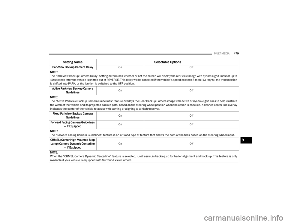
ParkView Backup Camera Delay On Off
NOTE:
The “ParkView Backup Camera Delay” setting determines whether or not the screen will display the rear view image with dynamic grid lines for up to
10 seconds after the vehicle is shifted out of REVERSE. This delay will be canceled if the vehicle’s speed exceeds 8 mph (13 km/h), the transmission
is shifted into PARK, or the ignition is switched to the OFF position. Active Parkview Backup Camera Guidelines On
Off
NOTE:
The “Active ParkView Backup Camera Guidelines” feature overlays the Rear Backup Camera image with active or dynamic grid lines to help illustrate
the width of the vehicle and its projected backup path, based on the steering wheel position when the option is checked. A dashed center line overlay
indicates the center of the vehicle to assist with parking or aligning to a hitch/receiver. Fixed Parkview Backup Camera Guidelines On
Off
Forward Facing Camera Guidelines — If Equipped On
Off
NOTE:
The “Forward Facing Camera Guidelines” feature is an off-road type of feature that shows the path of the tires based on the steering wheel input. CHMSL (Center High Mounted Stop Lamp) Camera Dynamic Centerline — If Equipped On
Off
NOTE:
When the “CHMSL Camera Dynamic Centerline” feature is selected, it will assist in backing up for trailer alignment and hook up. This feature is only
available if your vehicle is equipped with Surround View Camera.
Setting Name Selectable Options
9
20_DJD2_OM_EN_USC_t.book Page 479