ignition Ram 3500 2016 Repair Manual
[x] Cancel search | Manufacturer: RAM, Model Year: 2016, Model line: 3500, Model: Ram 3500 2016Pages: 919, PDF Size: 6.67 MB
Page 231 of 919
Sunshade Operation
The sunshade can be opened manually. However, the
sunshade will open automatically as the sunroof opens.
NOTE:The sunshade cannot be closed if the sunroof is
open.
Wind Buffeting
Wind buffeting can be described as the perception of
pressure on the ears or a helicopter-type sound in the
ears. Your vehicle may exhibit wind buffeting with the
windows down, or the sunroof (if equipped) in certain
open or partially open positions. This is a normal occur-
rence and can be minimized. If the buffeting occurs with
the rear windows open, open the front and rear windows
together to minimize the buffeting. If the buffeting occurs
with the sunroof open, adjust the sunroof opening to
minimize the buffeting or open any window.
Sunroof Maintenance
Use only a nonabrasive cleaner and a soft cloth to clean
the glass panel.
Ignition Off Operation
The power sunroof switch will remain active in Acces-
sory Delay for up to approximately ten minutes after the
ignition switch is turned to the LOCK position. Opening
either front door will cancel this feature.
NOTE: Ignition Off time is programmable through the
Uconnect System. Refer to “Uconnect Settings/Customer
Programmable Features” in “Understanding Your Instru-
ment Panel” for further information.
ELECTRICAL POWER OUTLETS
The auxiliary 12 Volt (13 Amp) power outlets can provide
power for in-cab accessories designed for use with the
standard “cigar lighter” plug. The 12 Volt power outlets
3
UNDERSTANDING THE FEATURES OF YOUR VEHICLE 229
Page 238 of 919
WARNING!
To avoid serious injury or death:
•Do not insert any objects into the receptacles.
• Do not touch with wet hands.
• Close the lid when not in use.
• If this outlet is mishandled, it may cause an electric
shock and failure.
AUXILIARY SWITCHES — IF EQUIPPED
There can be up to five auxiliary switches located in the
lower switch bank of the instrument panel which can be
used to power various electronic devices and PTO
(Power Take Off) – If Equipped. If Power Take Off is
equipped, it will take the place of the fifth Auxiliary
switch. Connections to the switches are found under the
hood in the connectors attached to the auxiliary Power
Distribution Center. You have the ability to configure the functionality of the
auxiliary switches via the Electronic Vehicle Information
Center (EVIC) or Driver Information Display (DID). All
switches can now be configured for setting the switch
type operation to latching or momentary, power source of
either battery or ignition, and ability to hold last state
across key cycles.
NOTE:
Holding last state conditions are met when
switch type is set to latching and power source is set to
ignition.
For further information on using the auxiliary switches,
please refer to the Ram Body Builders Guide by accessing
www.rambodybuilder.com and choosing the appropriate
links.
236 UNDERSTANDING THE FEATURES OF YOUR VEHICLE
Page 290 of 919
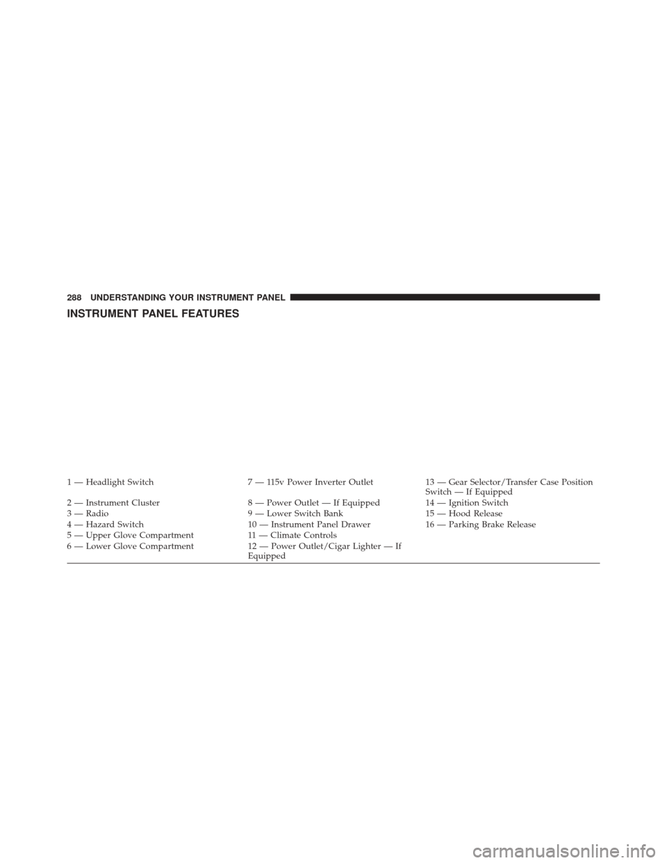
INSTRUMENT PANEL FEATURES
1 — Headlight Switch7 — 115v Power Inverter Outlet13 — Gear Selector/Transfer Case Position
Switch — If Equipped
2 — Instrument Cluster 8 — Power Outlet — If Equipped14 — Ignition Switch
3 — Radio 9 — Lower Switch Bank15 — Hood Release
4 — Hazard Switch 10 — Instrument Panel Drawer16 — Parking Brake Release
5 — Upper Glove Compartment 11 — Climate Controls
6 — Lower Glove Compartment 12 — Power Outlet/Cigar Lighter — If
Equipped
288 UNDERSTANDING YOUR INSTRUMENT PANEL
Page 292 of 919
1. Tachometer•Indicates the engine speed in revolutions per minute
(RPM x 1000).
2. Electronic Vehicle Information Center (EVIC) Display •When the appropriate conditions exist, this display
shows the Electronic Vehicle Information Center
(EVIC) messages. Refer to “Electronic Vehicle Infor-
mation Center” in “Understanding Your Instrument
Panel” for further information.
3. Speedometer •Indicates vehicle speed.
4. Fuel Gauge •The pointer shows the level of fuel in the fuel tank
when the Keyless Push Button Ignition is in the
ON/RUN position. •
The fuel pump symbol points to the side of the
vehicle where the fuel door is located.
5. Temperature Gauge •The temperature gauge shows engine coolant tem-
perature. Any reading within the normal range indi-
cates that the engine cooling system is operating
satisfactorily.
• The gauge pointer will likely indicate a higher tem-
perature when driving in hot weather, up mountain
grades, or when towing a trailer. It should not be
allowed to exceed the upper limits of the normal
operating range.
290 UNDERSTANDING YOUR INSTRUMENT PANEL
Page 296 of 919
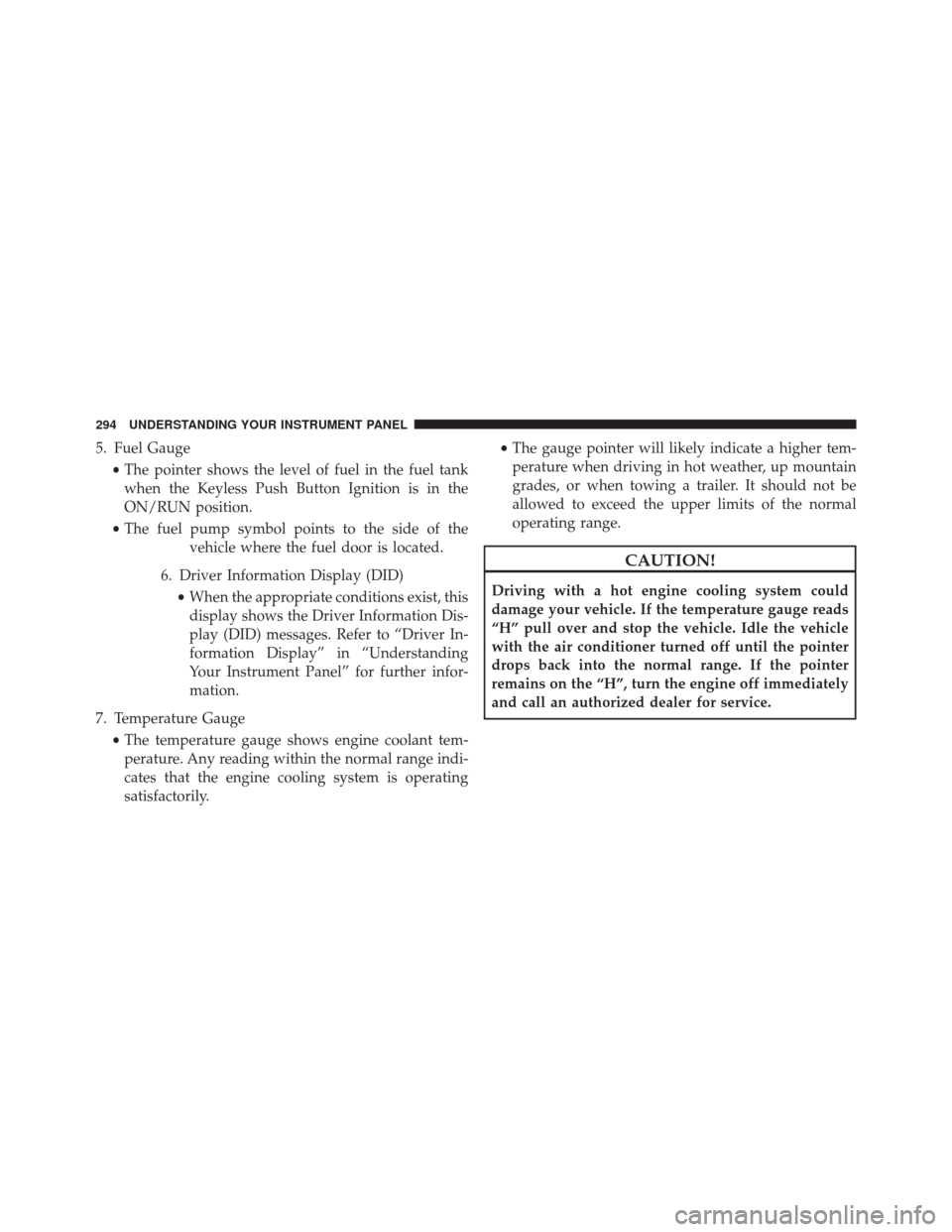
5. Fuel Gauge•The pointer shows the level of fuel in the fuel tank
when the Keyless Push Button Ignition is in the
ON/RUN position.
• The fuel pump symbol points to the side of the
vehicle where the fuel door is located.
6. Driver Information Display (DID) •When the appropriate conditions exist, this
display shows the Driver Information Dis-
play (DID) messages. Refer to “Driver In-
formation Display” in “Understanding
Your Instrument Panel” for further infor-
mation.
7. Temperature Gauge •The temperature gauge shows engine coolant tem-
perature. Any reading within the normal range indi-
cates that the engine cooling system is operating
satisfactorily. •
The gauge pointer will likely indicate a higher tem-
perature when driving in hot weather, up mountain
grades, or when towing a trailer. It should not be
allowed to exceed the upper limits of the normal
operating range.
CAUTION!
Driving with a hot engine cooling system could
damage your vehicle. If the temperature gauge reads
“H” pull over and stop the vehicle. Idle the vehicle
with the air conditioner turned off until the pointer
drops back into the normal range. If the pointer
remains on the “H”, turn the engine off immediately
and call an authorized dealer for service.
294 UNDERSTANDING YOUR INSTRUMENT PANEL
Page 298 of 919
Red Telltale Indicator Lights
Seat Belt Reminder Warning Light
Red TelltaleLight What It Means
Seat Belt Reminder Warning Light
When the ignition switch is first turned to ON/RUN, this light will turn on for four to eight
seconds as a bulb check. During the bulb check, if the driver’s seat belt is unbuckled, a
chime will sound. After the bulb check or when driving, if the driver ’s seat belt remains un-
buckled, the Seat Belt Reminder Light will flash or remain on continuously and a chime will
sound. Refer to “Occupant Restraints” in “Things To Know Before Starting Your Vehicle” for
further information.
296 UNDERSTANDING YOUR INSTRUMENT PANEL
Page 299 of 919
Air Bag Warning Light
Red TelltaleLight What It Means
Air Bag Warning Light
This light will turn on for four to eight seconds as a bulb check when the ignition switch is
first turned to ON/RUN. If the light is either not on during startup, stays on, or turns on
while driving, have the system inspected at an authorized dealer as soon as possible. This
light will illuminate with a single chime when a fault with the Air Bag Warning Light has
been detected, it will stay on until the fault is cleared. If the light comes on intermittently or
remains on while driving, have an authorized dealer service the vehicle immediately. Refer
to “Occupant Restraints” in “Things To Know Before Starting Your Vehicle” for further infor-
mation.
4
UNDERSTANDING YOUR INSTRUMENT PANEL 297
Page 301 of 919
The light will remain on until the cause is corrected.
NOTE:The light may flash momentarily during sharp
cornering maneuvers, which change fluid level condi-
tions. The vehicle should have service performed, and
the brake fluid level checked.
If brake failure is indicated, immediate repair is neces-
sary.
WARNING!
Driving a vehicle with the red brake light on is
dangerous. Part of the brake system may have failed.
It will take longer to stop the vehicle. You could have
a collision. Have the vehicle checked immediately.
Vehicles equipped with the Anti-Lock Brake System
(ABS) are also equipped with Electronic Brake Force
Distribution (EBD). In the event of an EBD failure, the Brake Warning Light will turn on along with the ABS
Light. Immediate repair to the ABS system is required.
Operation of the Brake Warning Light can be checked by
turning the ignition switch from the OFF position to the
ON/RUN position. The light should illuminate for ap-
proximately two seconds. The light should then turn off
unless the parking brake is applied or a brake fault is
detected. If the light does not illuminate, have the light
inspected by an authorized dealer.
The light also will turn on when the parking brake is
applied with the ignition switch in the ON/RUN posi-
tion.
NOTE:
This light shows only that the parking brake is
applied. It does not show the degree of brake application.
4
UNDERSTANDING YOUR INSTRUMENT PANEL 299
Page 305 of 919
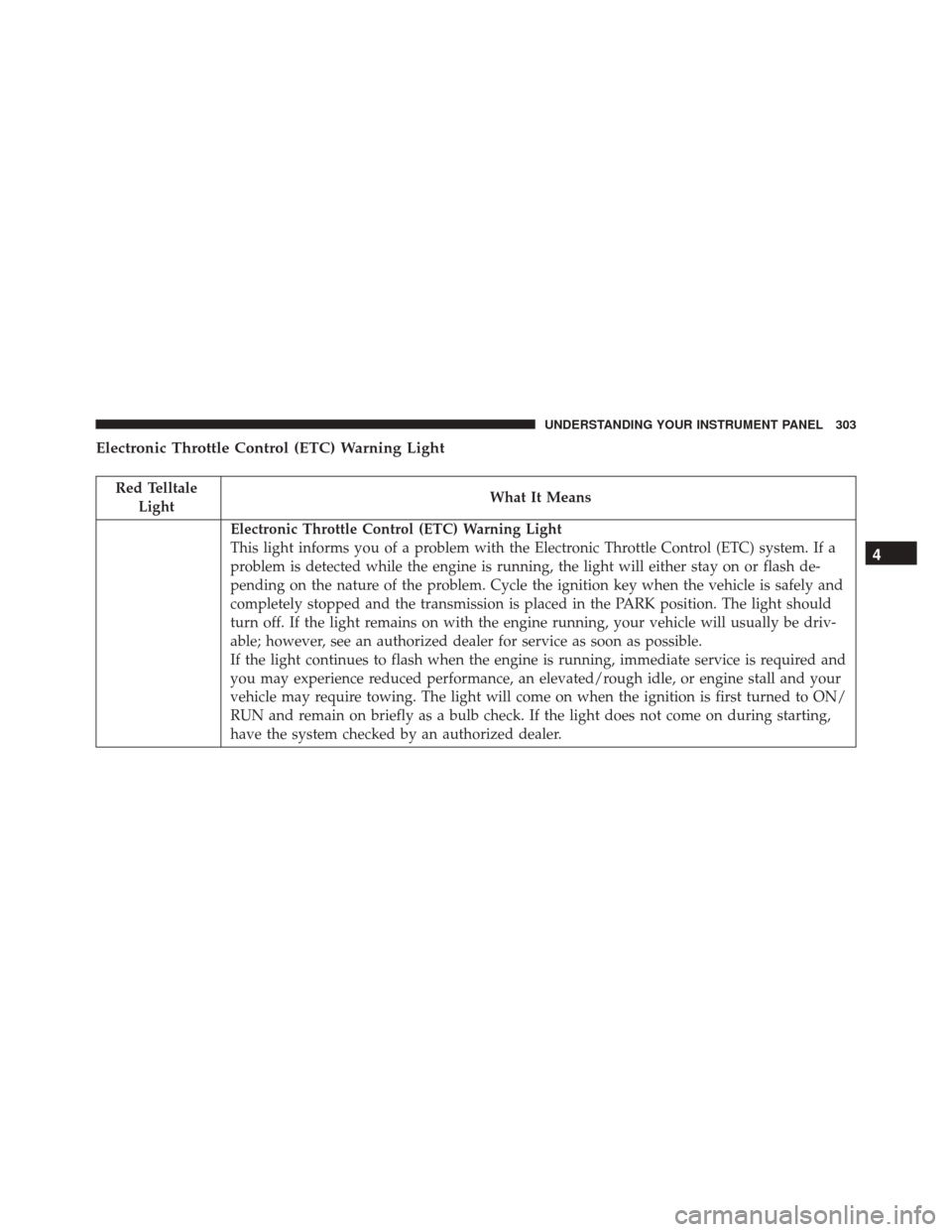
Electronic Throttle Control (ETC) Warning Light
Red TelltaleLight What It Means
Electronic Throttle Control (ETC) Warning Light
This light informs you of a problem with the Electronic Throttle Control (ETC) system. If a
problem is detected while the engine is running, the light will either stay on or flash de-
pending on the nature of the problem. Cycle the ignition key when the vehicle is safely and
completely stopped and the transmission is placed in the PARK position. The light should
turn off. If the light remains on with the engine running, your vehicle will usually be driv-
able; however, see an authorized dealer for service as soon as possible.
If the light continues to flash when the engine is running, immediate service is required and
you may experience reduced performance, an elevated/rough idle, or engine stall and your
vehicle may require towing. The light will come on when the ignition is first turned to ON/
RUN and remain on briefly as a bulb check. If the light does not come on during starting,
have the system checked by an authorized dealer.
4
UNDERSTANDING YOUR INSTRUMENT PANEL 303
Page 309 of 919
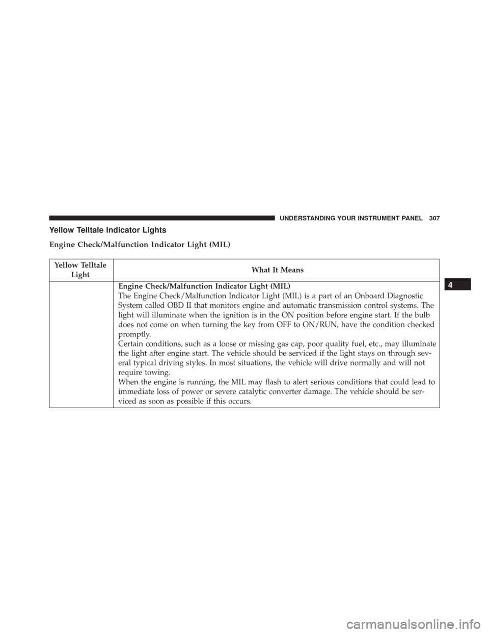
Yellow Telltale Indicator Lights
Engine Check/Malfunction Indicator Light (MIL)
Yellow TelltaleLight What It Means
Engine Check/Malfunction Indicator Light (MIL)
The Engine Check/Malfunction Indicator Light (MIL) is a part of an Onboard Diagnostic
System called OBD II that monitors engine and automatic transmission control systems. The
light will illuminate when the ignition is in the ON position before engine start. If the bulb
does not come on when turning the key from OFF to ON/RUN, have the condition checked
promptly.
Certain conditions, such as a loose or missing gas cap, poor quality fuel, etc., may illuminate
the light after engine start. The vehicle should be serviced if the light stays on through sev-
eral typical driving styles. In most situations, the vehicle will drive normally and will not
require towing.
When the engine is running, the MIL may flash to alert serious conditions that could lead to
immediate loss of power or severe catalytic converter damage. The vehicle should be ser-
viced as soon as possible if this occurs.4
UNDERSTANDING YOUR INSTRUMENT PANEL 307