fuel Ram 3500 2018 Owner's Manual
[x] Cancel search | Manufacturer: RAM, Model Year: 2018, Model line: 3500, Model: Ram 3500 2018Pages: 372, PDF Size: 7.1 MB
Page 85 of 372

rotate at the same speed. Low range provides
a greater gear reduction ratio to provide in-
creased torque at the wheels.
Refer to “Four-Wheel Drive Operation — If
Equipped” in “Starting And Operating” for
further information on four-wheel drive op-
eration and proper use.
— Wait To Start Light — If Equipped
The “Wait To Start” telltale will illuminate for
approximately two seconds when the ignition
is turned to the RUN position. It’s duration
may be longer based on colder operating
conditions. Vehicle will not initiate start until
telltale is no longer displayed. Refer to
“Starting The Engine” in “Starting And Op-
erating” for further information.
NOTE:
The “Wait To Start” telltale may not illumi-
nate if the intake manifold temperature is
warm enough.
— Water In Fuel Indicator Light — If
Equipped
The “Water In Fuel Indicator Light” will illu-
minate when there is water detected in the
fuel filters. If this light remains on, DO NOT
start the vehicle before you drain the water
from the fuel filters to prevent engine dam-
age. Refer to the “Draining Fuel/Water Sepa-
rator Filter” section in “Dealer Service” in
“Servicing And Maintenance” for further in-
formation.
— Low Diesel Exhaust Fluid (DEF) Indi-
cator Light — If Equipped
The Low Diesel Exhaust Fluid (DEF) Indicator
will illuminate if the vehicle is low on Diesel
Exhaust Fluid (DEF). Refer to “Starting And
Operating” for further information.
Green Indicator Lights
— Park/Headlight On Indicator Light
This indicator will illuminate when the park
lights or headlights are turned on.
— Front Fog Indicator Light — If
Equipped
This indicator will illuminate when the front
fog lights are on.
— Turn Signal Indicator Lights
When the left or right turn signal is activated,
the turn signal indicator will flash indepen-
dently and the corresponding exterior turn
signal lamps will flash. Turn signals can be
activated when the multifunction lever is
moved down (left) or up (right).
NOTE:
• A continuous chime will sound if the ve- hicle is driven more than 1 mile (1.6 km)
with either turn signal on.
• Check for an inoperative outside light bulb if either indicator flashes at a rapid rate.
—Cruise Control Set Indicator Light —
If Equipped
This light will turn on when the speed control
is set to the desired speed. Refer to “Speed
Control” in “Starting And Operating” for fur-
ther information.
83
Page 86 of 372

– 4WD AUTO Indicator Light — If
Equipped
This light alerts the driver that the vehicle is
in the four-wheel drive auto mode, and the
front axle is engaged, but the vehicle's power
is sent to the rear wheels. Four-wheel drive
will be automatically engaged when the ve-
hicle senses a loss of traction.
For further information on four-wheel drive
operation and proper use, refer to “Four-
Wheel Drive Operation — If Equipped” in
“Starting And Operating.”
White Indicator Lights
— Cruise Control Ready Indicator
This light will turn on when the speed control
is ready, but not set.
— Speed Control SET Indicator Light
— If Equipped
This light will turn on when the speed control
is set. Refer to “Speed Control — If
Equipped” in “Starting And Operating” for
further information.
— Hill Descent Control (HDC) Indicator
Light — If Equipped
This indicator shows when the Hill Descent
Control (HDC) feature is turned on. The lamp
will be on solid when HDC is armed. HDC can
only be armed when the transfer case is in the
“4WD LOW” position and the vehicle speed
is less then 30 mph (48 km/h). If these
conditions are not met while attempting to
use the HDC feature, the HDC indicator light
will flash on/off.
Blue Indicator Lights
— High Beam Indicator Light
This indicator shows that the high beam
headlights are on. With the low beams acti-
vated, push the multifunction lever forward
(toward the front of the vehicle) to turn on the
high beams. Pull the multifunction lever rear-
ward (toward the rear of the vehicle) to turn
off the high beams. If the high beams are off,
pull the lever toward you for a temporary high
beam on, "flash to pass" scenario.
ONBOARD DIAGNOSTIC SYSTEM —
OBD II
Your vehicle is equipped with a sophisticated
Onboard Diagnostic system called OBD II.
This system monitors the performance of the
emissions, engine, and transmission control
systems. When these systems are operating
properly, your vehicle will provide excellent
performance and fuel economy, as well as
engine emissions well within current govern-
ment regulations.
If any of these systems require service, the
OBD II system will turn on the Malfunction
Indicator Light (MIL). It will also store diag-
nostic codes and other information to assist
your service technician in making repairs.
Although your vehicle will usually be drivable
and not need towing, see your authorized
dealer for service as soon as possible.
CAUTION!
• Prolonged driving with the MIL on could
cause further damage to the emission
control system. It could also affect fuelGETTING TO KNOW YOUR INSTRUMENT PANEL
84
Page 91 of 372
CAUTION!
• The TPMS has been optimized for theoriginal equipment tires and wheels.
TPMS pressures and warning have been
established for the tire size equipped on
your vehicle. Undesirable system opera-
tion or sensor damage may result when
using replacement equipment that is not
of the same size, type, and/or style.
Aftermarket wheels can cause sensor
damage.
• Using aftermarket tire sealants may
cause the Tire Pressure Monitoring Sys-
tem (TPMS) sensor to become inoper-
able. After using an aftermarket tire
sealant it is recommended that you take
your vehicle to an authorized dealership
to have your sensor function checked.
• After inspecting or adjusting the tire
pressure always reinstall the valve stem
cap. This will prevent moisture and dirt
from entering the valve stem, which
could damage the TPMS sensor. NOTE:
• The TPMS is not intended to replace nor-
mal tire care and maintenance or to provide
warning of a tire failure or condition.
• The TPMS should not be used as a tire pressure gauge while adjusting your tire
pressure.
• Driving on a significantly under-inflated tire causes the tire to overheat and can lead to
tire failure. Under-inflation also reduces
fuel efficiency and tire tread life, and may
affect the vehicle’s handling and stopping
ability.
• The TPMS is not a substitute for proper tire maintenance, and it is the driver’s respon-
sibility to maintain correct tire pressure
using an accurate tire pressure gauge, even
if under-inflation has not reached the level
to trigger illumination of the TPM Telltale
Light.
• Seasonal temperature changes will affect tire pressure, and the TPMS will monitor
the actual tire pressure in the tire.
Premium System
The Tire Pressure Monitor System (TPMS)
uses wireless technology with wheel rim
mounted electronic sensors to monitor tire
pressure levels. Sensors, mounted to each
wheel as part of the valve stem, transmit tire
pressure readings to the receiver module.
NOTE:
It is particularly important for you to check
the tire pressure in all of the tires on your
vehicle monthly and to maintain the proper
pressure.
The TPMS consists of the following compo-
nents:
• Receiver module
• Four tire pressure monitoring sensors
• Various tire pressure monitoring systemmessages, which display in the instrument
cluster
• Tire pressure monitoring telltale light
89
Page 116 of 372
have skin or eye irritation, rinse the area
with cool water. For nose or throat irritation,
move to fresh air. If the irritation continues,
see your doctor. If these particles settle on
your clothing, follow the garment manufac-
turer’s instructions for cleaning.
Do not drive your vehicle after the air bags
have deployed. If you are involved in another
collision, the air bags will not be in place to
protect you.
WARNING!
Deployed air bags and seat belt preten-
sioners cannot protect you in another col-
lision. Have the air bags, seat belt preten-
sioners, and the seat belt retractor
assemblies replaced by an authorized
dealer immediately. Also, have the Occu-
pant Restraint Controller System serviced
as well.
NOTE:
• Air bag covers may not be obvious in the interior trim, but they will open during air
bag deployment. • After any collision, the vehicle should be
taken to an authorized dealer immediately.
Enhanced Accident Response System
In the event of an impact, if the communica-
tion network remains intact, and the power
remains intact, depending on the nature of
the event, the ORC will determine whether to
have the Enhanced Accident Response Sys-
tem perform the following functions:
• Cut off fuel to the engine.
• Flash hazard lights as long as the batteryhas power or until the hazard light button is
pressed. The hazard lights can be deacti-
vated by pressing the hazard light button.
• Turn on the interior lights, which remain on as long as the battery has power.
• Unlock the power door locks.
Enhanced Accident Response System Reset
Procedure
In order to reset the Enhanced Accident Re-
sponse System functions after an event, the
ignition switch must be changed from igni-
tion START or ON/RUN to ignition OFF. Care-
fully check the vehicle for fuel leaks in the engine compartment and on the ground near
the engine compartment and fuel tank before
resetting the system and starting the engine.
Maintaining Your Air Bag System
WARNING!
• Modifications to any part of the air bag
system could cause it to fail when you
need it. You could be injured if the air
bag system is not there to protect you.
Do not modify the components or wiring,
including adding any kind of badges or
stickers to the steering wheel hub trim
cover or the upper right side of the
instrument panel. Do not modify the
front bumper, vehicle body structure, or
add aftermarket side steps or running
boards.
• It is dangerous to try to repair any part of
the air bag system yourself. Be sure to
tell anyone who works on your vehicle
that it has an air bag system.
• Do not attempt to modify any part of your
air bag system. The air bag may inflate
accidentally or may not function prop-
SAFETY
114
Page 138 of 372
WARNING!
• ONLY use the driver’s side floor mat onthe driver’s side floor area. To check for
interference, with the vehicle properly
parked with the engine off, fully depress
the accelerator, the brake, and the
clutch pedal (if present) to check for
interference. If your floor mat interferes
with the operation of any pedal, or is not
secure to the floor, remove the floor mat
from the vehicle and place the floor mat
in your trunk.
• ONLY use the passenger’s side floor mat
on the passenger’s side floor area.
• ALWAYS make sure objects cannot fall or
slide into the driver’s side floor area
when the vehicle is moving. Objects can
become trapped under accelerator,
brake, or clutch pedals and could cause
a loss of vehicle control.
•
NEVER place any objects under the floor
mat (e.g., towels, keys, etc.). These ob-
jects could change the position of the
floor mat and may cause interference with
the accelerator, brake, or clutch pedals.
WARNING!
• If the vehicle carpet has been removed
and re-installed, always properly attach
carpet to the floor and check the floor
mat fasteners are secure to the vehicle
carpet. Fully depress each pedal to
check for interference with the accelera-
tor, brake, or clutch pedals then re-
install the floor mats.
• It is recommended to only use mild soap
and water to clean your floor mats. After
cleaning, always check your floor mat
has been properly installed and is se-
cured to your vehicle using the floor mat
fasteners by lightly pulling mat.
Periodic Safety Checks You
Should Make Outside The Vehicle
Tires
Examine tires for excessive tread wear and
uneven wear patterns. Check for stones,
nails, glass, or other objects lodged in the
tread or sidewall. Inspect the tread for cuts and cracks. Inspect sidewalls for cuts,
cracks, and bulges. Check the wheel bolts for
tightness. Check the tires (including spare)
for proper cold inflation pressure.
Lights
Have someone observe the operation of brake
lights and exterior lights while you work the
controls. Check turn signal and high beam
indicator lights on the instrument panel.
Door Latches
Check for proper closing, latching, and lock-
ing.
Fluid Leaks
Check area under the vehicle after overnight
parking for fuel, coolant, oil, or other fluid
leaks. Also, if gasoline fumes are detected or
if fuel, or brake fluid leaks are suspected. The
cause should be located and corrected imme-
diately.
SAFETY
136
Page 140 of 372

To Accelerate For Passing.........178
To Resume Speed .............178
To Deactivate ................178
PARKSENSE FRONT AND REAR PARK AS-
SIST — IF EQUIPPED ...........179
Cleaning The ParkSense System .....179
PARKVIEW REAR BACK UP CAMERA — IF
EQUIPPED................. .179
REFUELING THE VEHICLE —
GAS ENGINE ................ .181
Materials Added To Fuel ..........182
REFUELING THE VEHICLE— 1500 DIESEL
MODELS................... .182
Diesel Exhaust Fluid............183
Adding Diesel Exhaust Fluid........184
REFUELING THE VEHICLE — 2500/
3500 DIESEL MODELS ...........186
Diesel Exhaust Fluid............188
TRAILER TOWING.............191
Trailer Towing Weights (Maximum
Trailer Weight Ratings) ...........191
Towing Requirements ...........191
RECREATIONAL TOWING (BEHIND
MOTORHOME, ETC.)............196
Towing This Vehicle Behind Another
Vehicle....................196
Recreational Towing — Two-Wheel
Drive Models .................197
Recreational Towing — Four-Wheel
Drive Models .................197
STARTING AND OPERATING
138
Page 144 of 372
STARTING THE ENGINE — 3.0L
DIESEL ENGINE
Before starting your vehicle, adjust your seat,
both inside and outside mirrors, and fasten
your seat belts.
The starter is allowed to crank for up to
30-second intervals. Waiting a few minutes
between such intervals will protect the starter
from overheating.
WARNING!
• Before exiting a vehicle, always come toa complete stop, then shift the auto-
matic transmission into PARK and apply
the parking brake. Always make sure the
keyless ignition node is in the OFF
mode, remove the key fob from the ve-
hicle and lock the vehicle.
• Never leave children alone in a vehicle,
or with access to an unlocked vehicle.
Leaving children in a vehicle unattended
is dangerous for a number of reasons. A
child or others could be seriously or
fatally injured. Children should be
WARNING!
warned not to touch the parking brake,
brake pedal or the gear selector.
• Do not leave the key fob in or near the
vehicle, or in a location accessible to
children, and do not leave the ignition of
a vehicle equipped with Keyless Enter-
N-Go in the ACC or ON/RUN mode. A
child could operate power windows,
other controls, or move the vehicle.
• Do not leave children or animals inside
parked vehicles in hot weather. Interior
heat build-up may cause serious injury
or death.
NOTE:
Engine start up in very low ambient tempera-
ture could result in evident white smoke. This
condition will disappear as the engine warms
up.
CAUTION!
• The engine is allowed to crank as long as 30 seconds. If the engine fails to start
during this period, please wait at least
CAUTION!
two minutes for the starter to cool before
repeating start procedure.
• If the “Water in Fuel Indicator Light”
remains on, DO NOT START engine be-
fore you drain the water from the fuel
filters to avoid engine damage. Refer to
“Draining Fuel/Water Separator Filter”
in “Servicing And Maintenance” in your
Diesel Supplement on www.mopar.com/
en-us/care/owners-manual.html (U.S.
Residents) or www.owners.mopar.ca
(Canadian Residents) for further infor-
mation.
Normal Starting Using ENGINE
STOP/START Button
Observe the instrument panel cluster lights
when starting the engine.
NOTE:
Normal starting of either a cold or a warm
engine is obtained without pumping or press-
ing the accelerator pedal.
STARTING AND OPERATING
142
Page 145 of 372
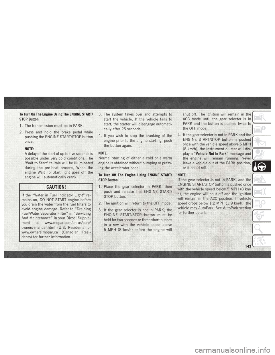
To Turn On The Engine Using The ENGINE START/
STOP Button
1. The transmission must be in PARK.
2. Press and hold the brake pedal whilepushing the ENGINE START/STOP button
once.
NOTE:
A delay of the start of up to five seconds is
possible under very cold conditions. The
"Wait to Start" telltale will be illuminated
during the pre-heat process, When the
engine Wait To Start light goes off the
engine will automatically crank.
CAUTION!
If the “Water in Fuel Indicator Light” re-
mains on, DO NOT START engine before
you drain the water from the fuel filters to
avoid engine damage. Refer to “Draining
Fuel/Water Separator Filter” in “Servicing
And Maintenance” in your Diesel Supple-
ment at www.mopar.com/en-us/care/
owners-manual.html (U.S. Residents) or
www.owners.mopar.ca (Canadian Resi-
dents) for further information. 3. The system takes over and attempts to
start the vehicle. If the vehicle fails to
start, the starter will disengage automati-
cally after 25 seconds.
4. If you wish to stop the cranking of the engine prior to the engine starting, push
the button again.
NOTE:
Normal starting of either a cold or a warm
engine is obtained without pumping or press-
ing the accelerator pedal.
To Turn Off The Engine Using ENGINE START/
STOP Button
1. Place the gear selector in PARK, then push and release the ENGINE START/
STOP button.
2. The ignition will return to the OFF mode.
3. If the gear selector is not in PARK, the ENGINE START/STOP button must be
held for two seconds or three short pushes
in a row with the vehicle speed above
5 MPH (8 km/h) before the engine will shut off. The ignition will remain in the
ACC mode until the gear selector is in
PARK and the button is pushed twice to
the OFF mode.
4. If the gear selector is not in PARK and the ENGINE START/STOP button is pushed
once with the vehicle speed above 5 MPH
(8 km/h), the instrument cluster will dis-
play a “Vehicle Not In Park” message and
the engine will remain running. Never
leave a vehicle out of the PARK position,
or it could roll.
NOTE:
If the gear selector is not in PARK, and the
ENGINE START/STOP button is pushed once
with the vehicle speed below 5 MPH (8 km/
h), the engine will shut off and the ignition
will remain in the ACC position. If vehicle
speed drops below 1.2 MPH (1.9 km/h), the
vehicle may AutoPark. See AutoPark section
for further details.
143
Page 147 of 372
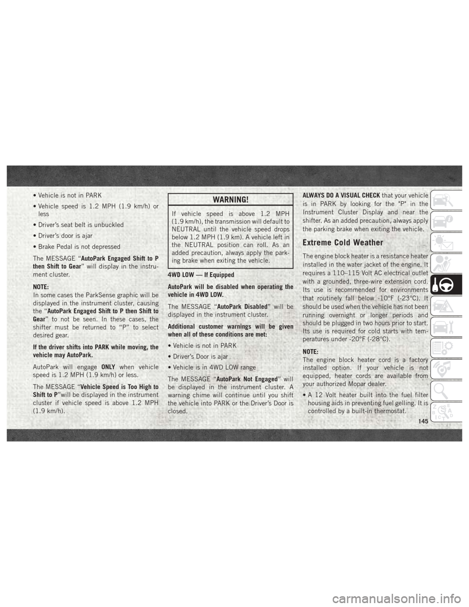
• Vehicle is not in PARK
• Vehicle speed is 1.2 MPH (1.9 km/h) orless
• Driver’s seat belt is unbuckled
• Driver’s door is ajar
• Brake Pedal is not depressed
The MESSAGE “AutoPark Engaged Shift to P
then Shift to Gear” will display in the instru-
ment cluster.
NOTE:
In some cases the ParkSense graphic will be
displayed in the instrument cluster, causing
the “AutoPark Engaged Shift to P then Shift to
Gear” to not be seen. In these cases, the
shifter must be returned to “P” to select
desired gear.
If the driver shifts into PARK while moving, the
vehicle may AutoPark.
AutoPark will engage ONLYwhen vehicle
speed is 1.2 MPH (1.9 km/h) or less.
The MESSAGE “Vehicle Speed is Too High to
Shift to P”will be displayed in the instrument
cluster if vehicle speed is above 1.2 MPH
(1.9 km/h).WARNING!
If vehicle speed is above 1.2 MPH
(1.9 km/h), the transmission will default to
NEUTRAL until the vehicle speed drops
below 1.2 MPH (1.9 km). A vehicle left in
the NEUTRAL position can roll. As an
added precaution, always apply the park-
ing brake when exiting the vehicle.
4WD LOW — If Equipped
AutoPark will be disabled when operating the
vehicle in 4WD LOW.
The MESSAGE “AutoPark Disabled” will be
displayed in the instrument cluster.
Additional customer warnings will be given
when all of these conditions are met:
• Vehicle is not in PARK
• Driver’s Door is ajar
• Vehicle is in 4WD LOW range
The MESSAGE “AutoPark Not Engaged” will
be displayed in the instrument cluster. A
warning chime will continue until you shift
the vehicle into PARK or the Driver’s Door is
closed. ALWAYS DO A VISUAL CHECK
that your vehicle
is in PARK by looking for the "P" in the
Instrument Cluster Display and near the
shifter. As an added precaution, always apply
the parking brake when exiting the vehicle.
Extreme Cold Weather
The engine block heater is a resistance heater
installed in the water jacket of the engine. It
requires a 110–115 Volt AC electrical outlet
with a grounded, three-wire extension cord.
Its use is recommended for environments
that routinely fall below -10°F (-23°C). It
should be used when the vehicle has not been
running overnight or longer periods and
should be plugged in two hours prior to start.
Its use is required for cold starts with tem-
peratures under -20°F (-28°C).
NOTE:
The engine block heater cord is a factory
installed option. If your vehicle is not
equipped, heater cords are available from
your authorized Mopar dealer.
• A 12 Volt heater built into the fuel filter housing aids in preventing fuel gelling. It is
controlled by a built-in thermostat.
145
Page 150 of 372
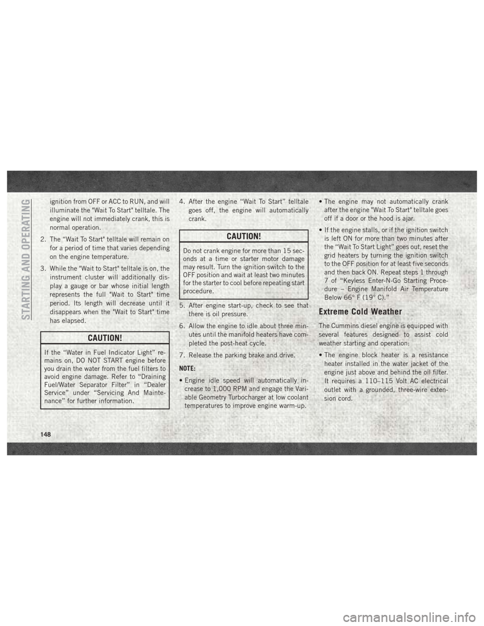
ignition from OFF or ACC to RUN, and will
illuminate the "Wait To Start" telltale. The
engine will not immediately crank, this is
normal operation.
2. The “Wait To Start" telltale will remain on for a period of time that varies depending
on the engine temperature.
3. While the "Wait to Start" telltale is on, the instrument cluster will additionally dis-
play a gauge or bar whose initial length
represents the full "Wait to Start" time
period. Its length will decrease until it
disappears when the "Wait to Start" time
has elapsed.
CAUTION!
If the “Water in Fuel Indicator Light” re-
mains on, DO NOT START engine before
you drain the water from the fuel filters to
avoid engine damage. Refer to “Draining
Fuel/Water Separator Filter” in “Dealer
Service” under “Servicing And Mainte-
nance” for further information. 4. After the engine “Wait To Start” telltale
goes off, the engine will automatically
crank.
CAUTION!
Do not crank engine for more than 15 sec-
onds at a time or starter motor damage
may result. Turn the ignition switch to the
OFF position and wait at least two minutes
for the starter to cool before repeating start
procedure.
5. After engine start-up, check to see that there is oil pressure.
6. Allow the engine to idle about three min- utes until the manifold heaters have com-
pleted the post-heat cycle.
7. Release the parking brake and drive.
NOTE:
• Engine idle speed will automatically in- crease to 1,000 RPM and engage the Vari-
able Geometry Turbocharger at low coolant
temperatures to improve engine warm-up. • The engine may not automatically crank
after the engine "Wait To Start" telltale goes
off if a door or the hood is ajar.
• If the engine stalls, or if the ignition switch is left ON for more than two minutes after
the “Wait To Start Light” goes out, reset the
grid heaters by turning the ignition switch
to the OFF position for at least five seconds
and then back ON. Repeat steps 1 through
7 of “Keyless Enter-N-Go Starting Proce-
dure – Engine Manifold Air Temperature
Below 66° F (19° C).”
Extreme Cold Weather
The Cummins diesel engine is equipped with
several features designed to assist cold
weather starting and operation:
• The engine block heater is a resistance
heater installed in the water jacket of the
engine just above and behind the oil filter.
It requires a 110–115 Volt AC electrical
outlet with a grounded, three-wire exten-
sion cord.STARTING AND OPERATING
148