fuel Ram 3500 2018 Owner's Manual
[x] Cancel search | Manufacturer: RAM, Model Year: 2018, Model line: 3500, Model: Ram 3500 2018Pages: 372, PDF Size: 7.1 MB
Page 151 of 372
NOTE:
The engine block heater cord is a factory
installed option. If your vehicle is not
equipped, heater cords are available from
your authorized Mopar dealer.
• A 12 Volt heater built into the fuel filterhousings aid in preventing fuel gelling. It is
controlled by a built-in thermostat.
• A heated intake air system both improves engine starting and reduces the amount of
white smoke generated by a warming
engine.NORMAL OPERATION — 3.0L DIESEL
ENGINE
Observe the following when the diesel engine
is operating.
• All message center lights are off.
• Malfunction Indicator Light (MIL) is off.
• Engine Oil Pressure telltale is not illumi-nated.
• Voltmeter operation:
The voltmeter may show a gauge fluctuation
at various engine temperatures. This is
caused by the glow plug heating system. The
number of cycles and the length of the cy-
cling operation is controlled by the engine
control module. Glow plug heater operation
can run for several minutes, once the heater
operation is complete the voltmeter needle
will stabilize.
Cold Weather Precautions
Operation in ambient temperature below
32°F (0°C) may require special consider-
ations. The following charts suggest these
options:
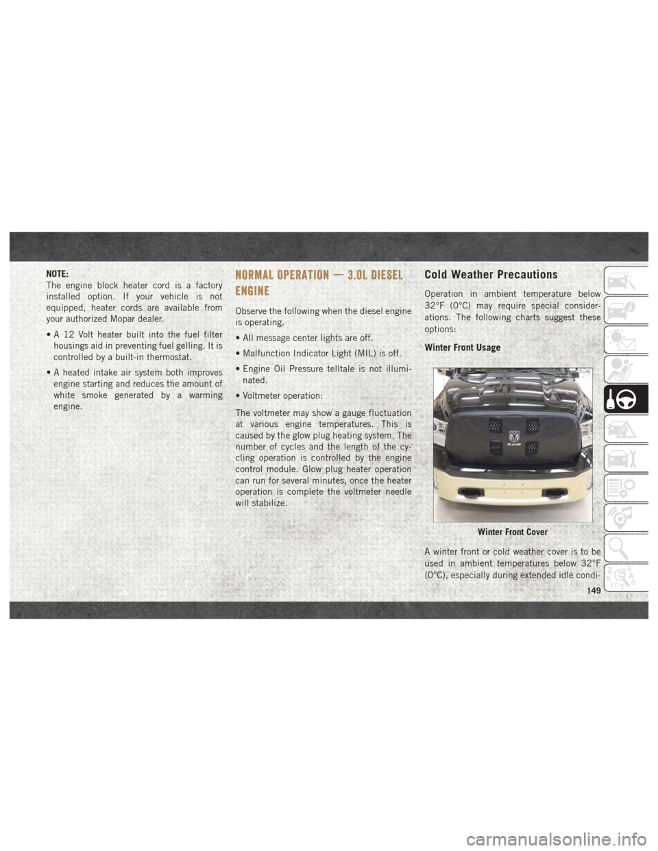
Winter Front Usage
A winter front or cold weather cover is to be
used in ambient temperatures below 32°F
(0°C), especially during extended idle condi-
Winter Front Cover
149
Page 153 of 372
NORMAL OPERATION — 6.7L DIESEL
ENGINE
Observe the following when the engine is
operating.
• All message center lights are off.
• Malfunction Indicator Light (MIL) is off.
• Engine oil pressure is above 10 psi(69 kPa) at idle.
• Voltmeter operation:
The voltmeter may show a gauge fluctuation
at various engine temperatures. This cycling
operation is caused by the post-heat cycle of
the intake manifold heater system. The num-
ber of cycles and the length of the cycling
operation is controlled by the engine control
module. Post-heat operation can run for sev-
eral minutes, and then the electrical system
and voltmeter needle will stabilize.
The cycling action will cause temporary dim-
ming of the headlamps, interior lamps, and
also a noticeable reduction in blower motor
speed.
Cold Weather Precautions
Operation in ambient temperature below
32°F (0°C) may require special consider-
ations. The following charts suggest these
options:
Winter Front Cover Usage
A winter front or cold weather cover is to be
used in ambient temperatures below 32°F
(0°C), especially during extended idle condi-
tions. This cover is equipped with four flaps
for managing total grille opening in varying
ambient temperatures. If a winter front or
cold weather cover is to be used the flaps
should be left in the full open position to
allow air flow to the charge air cooler and
automatic transmission oil cooler. When am-
bient temperatures drop below 0°F (-17°C)
the four flaps need to be closed. A suitable
cold weather cover is available from your
Mopar dealer.
Engine Idling
Avoid prolonged idling, long periods of idling
may be harmful to your engine because com-
bustion chamber temperatures can drop so low that the fuel may not burn completely.
Incomplete combustion allows carbon and
varnish to form on piston rings, engine valves,
and injector nozzles. Also, the unburned fuel
can enter the crankcase, diluting the oil and
causing rapid wear to the engine.
If the engine is allowed to idle or the truck is
driven on low engine speed drive cycles for
more than 2 hours, the system will automati-
cally enter an emissions operating mode that
will increase the engine idle speed to
900 RPM (1050 RPM for Chassis Cab).
While in this mode, which is designed to help
maintain the diesel particulate filter, the en-
gine idle speed will return to normal when the
brake pedal is applied. A small change in
engine tone or a slight change in engine
performance while accelerating may also be
noticeable at speeds below 20 mph
(32 kmh). This operating mode may last for
up to an hour of idle time, or around 20 min-
utes of driving time.
Your truck may have been ordered with an
optional voltage monitoring idle up feature. If
a load is placed on the electrical system while
the truck is in park, this feature will attempt
151
Page 156 of 372
ENGINE BREAK-IN
RECOMMENDATIONS — 3.0L DIESEL
The diesel engine does not require a break-in
period due to its construction. Normal opera-
tion is allowed, providing the following rec-
ommendations are followed:
• Warm up the engine before placing it underload.
• Do not operate the engine at idle for pro- longed periods.
• Use the appropriate transmission gear to prevent engine lugging.
• Observe vehicle oil pressure and tempera- ture indicators.
• Check the coolant and oil levels frequently.
• Vary throttle position at highway speeds when carrying or towing significant weight.
NOTE:
Light duty operation such as light trailer
towing or no load operation will extend the
time before the engine is at full efficiency.
Reduced fuel economy and power may be
seen at this time. The engine oil installed in the engine at the
factory is a high-quality energy conserving
type lubricant. Oil changes should be consis-
tent with anticipated climate conditions un-
der which vehicle operations will occur. The
recommended viscosity and quality grades
are shown under “Fluids And Lubricants” in
"Technical Specifications” in this manual.
NON-DETERGENT OR STRAIGHT MINERAL
OILS MUST NEVER BE USED.
ENGINE BREAK-IN
RECOMMENDATIONS — 6.7L DIESEL
The Cummins turbocharged diesel engine
does not require a break-in period due to its
construction. Normal operation is allowed,
providing the following recommendations are
followed:
• Warm up the engine before placing it under
load.
• Do not operate the engine at idle for pro- longed periods.
• Use the appropriate transmission gear to prevent engine lugging. • Observe vehicle oil pressure and tempera-
ture indicators.
• Check the coolant and oil levels frequently.
• Vary throttle position at highway speeds when carrying or towing significant weight.
NOTE:
Light duty operation such as light trailer
towing or no load operation will extend the
time before the engine is at full efficiency.
Reduced fuel economy and power may be
seen at this time.
For additional vehicle break-in requirements,
refer to “Trailer Towing” in “Starting And
Operating” of the Owner’s Manual.
Because of the construction of the Cummins
turbocharged diesel engine, engine run-in is
enhanced by loaded operating conditions
which allow the engine parts to achieve final
finish and fit during the first 6,000 miles
(10 000 km).STARTING AND OPERATING
154
Page 167 of 372

4WD LOCK
Four-Wheel Drive Lock High Range — This
range maximizes torque to the front drive-
shaft, forcing the front and rear wheels to
rotate at the same speed. Additional traction
for loose, slippery road surfaces only.
4WD LOW
Four-Wheel Drive Low Range — This range
provides low speed four-wheel drive. It maxi-
mizes torque to the front driveshaft, forcing
the front and rear wheels to rotate at the same
speed. This range provides additional trac-
tion and maximum pulling power for loose,
slippery road surfaces only. Do not exceed
25 mph (40 km/h).
NEUTRAL (N)
Neutral — This range disengages both the
front and rear driveshafts from the pow-
ertrain. To be used for flat towing behind
another vehicle. Refer to “Recreational Tow-
ing” in this section for further information.This electronically shifted transfer case is
designed to be driven in the two-wheel drive
position (2WD) or four-wheel drive position
(4WD AUTO) for normal street and highway
conditions on dry hard surfaced roads). Driv-
ing the vehicle in 2WD will have greater fuel
economy benefits as the front axle is not
engaged in 2WD.
For variable driving conditions, the 4WD
AUTO mode can be used. In this mode, the
front axle is engaged, but the vehicle's power
is sent to the rear wheels. Four-wheel drive
will be automatically engaged when the ve-
hicle senses a loss of traction. Because the
front axle is engaged, this mode will result in
lower fuel economy than the 2WD mode.
When additional traction is required, the
transfer case 4WD LOCK and 4WD LOW po-
sitions can be used to maximize torque to the
front driveshaft, forcing the front and rear
wheels to rotate at the same speed. This is
accomplished by rotating the 4WD Control
Switch to the desired position.Refer to “Shifting Procedure” in the “Start-
ing And Operating” section of you Owner’s
Manual for specific shifting instructions.
WARNING!
You or others could be injured or killed if
you leave the vehicle unattended with the
transfer case in the NEUTRAL position
without first fully engaging the parking
brake. The transfer case NEUTRAL posi-
tion disengages both the front and rear
drive shafts from the powertrain and will
allow the vehicle to roll, even if the trans-
mission is in PARK. The parking brake
should always be applied when the driver
is not in the vehicle.
165
Page 169 of 372
4WD LOW
Four-Wheel Drive Low Range — This range
provides low speed four-wheel drive. It maxi-
mizes torque to the front driveshaft, forcing
the front and rear wheels to rotate at the same
speed. This range provides additional trac-
tion and maximum pulling power for loose,
slippery road surfaces only. Do not exceed
25 mph (40 km/h).
NEUTRAL (N)
Neutral — This range disengages both the
front and rear driveshafts from the pow-
ertrain. To be used for flat towing behind
another vehicle. Refer to “Recreational Tow-
ing” in this section for further information.
This electronically shifted transfer case is
designed to be driven in the two–wheel drive
position (2WD) for normal street and highway
conditions on dry hard surfaced roads). Driv-
ing the vehicle in 2WD will have greater fuel
economy benefits as the front axle is not
engaged in 2WD.When additional traction is required, the
transfer case 4WD LOCK and 4WD LOW po-
sitions can be used to maximize torque to the
front driveshaft, forcing the front and rear
wheels to rotate at the same speed. This is
accomplished by pushing the desired posi-
tion on the 4WD control switch.
Refer to “Shifting Procedure” in the “Start-
ing And Operating” section of your Owner’s
Manual for specific shifting instructions.
WARNING!
• You or others could be injured or killed if
you leave the vehicle unattended with
the transfer case in the NEUTRAL (N)
position without first fully engaging the
parking brake. The transfer case NEU-
TRAL (N) position disengages both the
front and rear drive shaft from the pow-
ertrain, and will allow the vehicle to roll,
even if the automatic transmission is in
PARK (or manual transmission is in
gear). The parking brake should always
be applied when the driver is not in the
vehicle.
WARNING!
• The transmission may not engage PARKif the vehicle is moving. Always bring the
vehicle to a complete stop before shift-
ing to PARK, and verify that the trans-
mission gear position indicator solidly
indicates PARK (P) without blinking. En-
sure that the vehicle is completely
stopped, and the PARK position is prop-
erly indicated, before exiting the ve-
hicle.
167
Page 171 of 372

4WD LOCK
Four-Wheel Drive Lock High Range — This
range maximizes torque to the front drive-
shaft, forcing the front and rear wheels to
rotate at the same speed. Additional traction
for loose, slippery road surfaces only.
4WD LOW
Four-Wheel Drive Low Range — This range
provides low speed four-wheel drive. It maxi-
mizes torque to the front driveshaft, forcing
the front and rear wheels to rotate at the same
speed. This range provides additional trac-
tion and maximum pulling power for loose,
slippery road surfaces only. Do not exceed
25 mph (40 km/h).
NEUTRAL (N)
Neutral — This range disengages both the
front and rear driveshafts from the pow-
ertrain. To be used for flat towing behind
another vehicle. Refer to “Recreational Tow-
ing” in this section for further information.
This electronically shifted transfer case is
designed to be driven in the two–wheel drive
position (2WD) or four-wheel drive position
(4WD AUTO) for normal street and highwayconditions on dry hard surfaced roads). Driv-
ing the vehicle in 2WD will have greater fuel
economy benefits as the front axle is not
engaged in 2WD.
For variable driving conditions, the 4WD
AUTO mode can be used. In this mode, the
front axle is engaged, but the vehicle's power
is sent to the rear wheels. Four-wheel drive
will be automatically engaged when the ve-
hicle senses a loss of traction. Because the
front axle is engaged, this mode will result in
lower fuel economy than the 2WD mode.
When additional traction is required, the
transfer case 4WD LOCK and 4WD LOW po-
sitions can be used to maximize torque to the
front driveshaft, forcing the front and rear
wheels to rotate at the same speed. This is
accomplished pushing the desired position
on the 4WD Control Switch.
Refer to “Shifting Procedure” in the “Start-
ing And Operating” section of your Owner’s
Manual for further details.WARNING!
• You or others could be injured or killed if
you leave the vehicle unattended with
the transfer case in the NEUTRAL (N)
position without first fully engaging the
parking brake. The transfer case NEU-
TRAL (N) position disengages both the
front and rear drive shaft from the pow-
ertrain, and will allow the vehicle to roll,
even if the automatic transmission is in
PARK (or manual transmission is in
gear). The parking brake should always
be applied when the driver is not in the
vehicle.
• The transmission may not engage PARK
if the vehicle is moving. Always bring the
vehicle to a complete stop before shift-
ing to PARK, and verify that the trans-
mission gear position indicator solidly
indicates PARK (P) without blinking. En-
sure that the vehicle is completely
stopped, and the PARK position is prop-
erly indicated, before exiting the ve-
hicle.
169
Page 183 of 372

REFUELING THE VEHICLE — GAS
ENGINE
The fuel filler cap (gas cap) is located behind
the fuel filler door, on the left side of the
vehicle. Open the fuel door and remove the
fuel cap by turning it counter-clockwise.
NOTE:
When removing the fuel filler cap, lay the cap
tether in the hook, located on the fuel filler
door.
WARNING!
• Never have any smoking materials lit inor near the vehicle when the gas cap is
removed or the tank is being filled.
• Never add fuel to the vehicle when the
engine is running.
• A fire may result if gasoline is pumped
into a portable container that is inside of
a vehicle. You could be burned. Always
place gas containers on the ground while
filling.
CAUTION!
• Damage to the fuel system or emissionscontrol system could result from using
an improper fuel tank filler tube cap.
• A poorly fitting fuel filler cap could let
impurities into the fuel system.
• A poorly fitting fuel filler cap may cause
the “Malfunction Indicator Light (MIL)”
to turn on.
• To avoid fuel spillage and overfilling, do
not “top off” the fuel tank after filling.
When the fuel nozzle “clicks” or shuts
off, the fuel tank is full.
NOTE:
• When the fuel nozzle “clicks” or shuts off, the fuel tank is full.
• Tighten the gas cap until you hear a “click- ing” sound. This is an indication that the
gas cap is tightened properly. The MIL in
the instrument cluster may turn on if the
gas cap is not secured properly. Make sure
that the gas cap is tightened each time the
vehicle is refueled.
WARNING!
Static electricity can cause an ignition of
flammable liquid, vapor or gas in any ve-
hicle or trailer. To reduce risk of serious
injury or death when filling containers:
• Always place container on the ground before filling.
• Keep the pump nozzle in contact with
the container when you are filling it.
• Use only approved containers for flam-
mable liquid.
• Do not leave container unattended while
filling.
• A static electric charge could cause a
spark and fire hazard.
181
Page 184 of 372

Materials Added To Fuel
Designated TOP TIER
Detergent Gasoline
contains a higher level
of detergents to fur-
ther aide in minimiz-
ing engine and fuel
system deposits. When
available, the usage of
Top Tier Detergent gasoline is recommended.
Visit www.toptiergas.com for a list of TOP
TIER Detergent Gasoline Retailers.
Indiscriminate use of fuel system cleaning
agents should be avoided. Many of these
materials intended for gum and varnish re-
moval may contain active solvents or similar
ingredients. These can harm fuel system gas-
ket and diaphragm materials.
REFUELING THE VEHICLE—
1500 DIESEL MODELS
1. Open the fuel filler door.NOTE:
There is no fuel filler cap. A flapper door
inside the filler pipe seals the system. 2. Insert the fuel nozzle fully into the filler
pipe – the nozzle opens and holds the
flapper door while refueling.
3. Fill the vehicle with fuel – when the fuel nozzle “clicks” or shuts off the fuel tank is
full.
4. Remove the fuel nozzle and close the fuel door.
Emergency Fuel Can Refueling
Most fuel cans will not open the flapper door.
A funnel is provided to open the flapper door
to allow emergency refueling with a fuel can.
1. Retrieve fuel funnel from the jack kit located under the front passenger seat.
Fill Locations
1 — Diesel Exhaust Fluid (DEF) Fill
Location
2 — Diesel Fuel Fill Location
STARTING AND OPERATING
182
Page 185 of 372

2. Insert funnel into same filler pipe openingas the fuel nozzle.
NOTE:
Ensure funnel is inserted fully to hold
flapper door open. 3. Pour fuel into funnel opening.
4. Remove funnel from filler pipe, clean off
prior to putting back in the jack kit.
WARNING!
• Never have any smoking materials lit inor near the vehicle when the fuel door is
open or the tank is being filled.
• Never add fuel when the engine is run-
ning. This is in violation of most state
and federal fire regulations and may
cause the “Malfunction Indicator Light”
to turn on.
• A fire may result if fuel is pumped into a
portable container that is inside of a
vehicle. You could be burned. Always
place fuel containers on the ground
while filling.
CAUTION!
To avoid fuel spillage and overfilling, do
not “top off” the fuel tank after filling.
Diesel Exhaust Fluid
Your vehicle is equipped with a Selective
Catalytic Reduction system to meet the very
stringent diesel emissions standards required
by the Environmental Protection Agency.
The purpose of the SCR system is to reduce
levels of NOx (oxides of nitrogen emitted from
engines) that are harmful to our health and
the environment to a near-zero level. Small
quantities of Diesel Exhaust Fluid (DEF) is
injected into the exhaust upstream of a cata-
lyst where, when vaporized, it converts smog-
forming nitrogen oxides (NOx) into harmless
nitrogen (N2) and water vapor (H2O), two
natural components of the air we breathe.
You can operate with the comfort that your
vehicle is contributing to a cleaner, healthier
world environment for this and generations to
come.
System Overview
This vehicle is equipped with a Diesel Ex-
haust Fluid (DEF) injection system and a
Selective Catalytic Reduction (SCR) catalyst
to meet the emission requirements.
Fill Locations And Funnel Useage
1 — Diesel Exhaust Fluid (DEF) Fill
Location
2 — Diesel Fuel Fill Location
3 — Emergency Diesel Fuel Fill Funnel
183
Page 186 of 372
The DEF injection system consists of the
following components:
• DEF tank
• DEF pump
• DEF injector
• Electronically-heated DEF lines
• NOx sensors
• Temperature sensors
• SCR catalyst
The DEF injection system and SCR catalyst
enable the achievement of diesel emissions
requirements; while maintaining outstanding
fuel economy, drivability, torque and power
ratings.
Refer to “Instrument Cluster Display” in
“Getting To Know Your Instrument Panel” for
system messages and warnings.
NOTE:
• Your vehicle is equipped with a DEF injec-tion system. You may occasionally hear an
audible clicking noise from under the ve-
hicle at a stop. This is normal operation. • The DEF pump will run for a period of time
after engine shutdown to purge the DEF
system. This is normal operation and may
be audible from the rear of the vehicle.
Adding Diesel Exhaust Fluid
The DEF gauge (located on the instrument
cluster) will display the level of DEF remain-
ing in the tank. Refer to “Instrument Cluster”
and “Instrument Cluster Descriptions” in
“Getting To Know Your Instrument Panel” for
further information.
NOTE:
• Driving conditions (altitude, vehicle speed,load, etc.) will effect the amount of DEF
that is used in your vehicle.
• Another factor is that outside temperature can affect DEF consumption. In cold con-
ditions, 12° F (-11° C) and below, the DEF
gauge needle can stay on a fixed position
and may not move for extended periods of
time. This is a normal function of the sys-
tem. • There is an electric heater inside the DEF
tank that automatically works when neces-
sary. And if the DEF supply does freeze, the
truck will operate normally until it thaws.
DEF Fill Procedure
NOTE:
Refer to “Fluids And Lubricants” in “Techni-
cal Specifications” for the correct fluid type.
1. Remove cap from DEF tank (located on
drivers side of the vehicle or in fuel door).
STARTING AND OPERATING
184