radio Ram 3500 2018 Owner's Manual
[x] Cancel search | Manufacturer: RAM, Model Year: 2018, Model line: 3500, Model: Ram 3500 2018Pages: 372, PDF Size: 7.1 MB
Page 53 of 372

2. Reach into the opening beneath the cen-ter of the hood and push the safety latch
lever to the left to release it, before raising
the hood.
To Close The Hood
Lower the hood to approximately 12 inches
(30 cm) from the engine compartment and
drop it. Make sure that the hood is completely
closed.
WARNING!
Be sure the hood is fully latched before
driving your vehicle. If the hood is not fully
latched, it could open when the vehicle is
in motion and block your vision. Failure to
follow this warning could result in serious
injury or death.
CAUTION!
To prevent possible damage, do not slam
the hood to close it. Use a firm downward
push at the front center of the hood to
ensure that both latches engage.
UNIVERSAL GARAGE DOOR OPENER
(HOMELINK)
• HomeLink replaces up to three hand-heldtransmitters that operate devices such as
garage door openers, motorized gates,
lighting or home security systems. The
HomeLink unit is powered by your vehicles
12 Volt battery. • The HomeLink buttons that are located in
the overhead console or sunvisor designate
the three different HomeLink channels.
• To operate HomeLink, push and release any of the programmed HomeLink buttons.
These buttons will activate the devices they
are programmed to with each press of the
corresponding HomeLink button.
Before You Begin Programming
HomeLink
For efficient programming and accurate
transmission of the radio-frequency signal, it
is recommended that a new battery be placed
in the hand-held transmitter of the device
that is being programmed to the HomeLink
system. Make sure your hand-held transmit-
ter is programmed to activate the device you
are trying to program your HomeLink button
to.
Ensure that your vehicle is parked outside of
the garage before you begin programming.
It is recommended that you erase all the
channels of your HomeLink before you use it
for the first time.
HomeLink Buttons
51
Page 56 of 372

WARNING!
• Your motorized door or gate will openand close while you are programming
the universal transceiver. Do not pro-
gram the transceiver if people or pets are
in the path of the door or gate.
• Do not run your vehicle in a closed
garage or confined area while program-
ming the transceiver. Exhaust gas from
your vehicle contains Carbon Monoxide
(CO) which is odorless and colorless.
Carbon Monoxide is poisonous when in-
haled and can cause you and others to
be severely injured or killed.
Programming HomeLink To A
Miscellaneous Device
Refer to “Programming HomeLink To A Ga-
rage Door Opener” for the procedure on how
to program HomeLink to a miscellaneous
device, as it follows the same procedure. Be
sure to determine if the device has a rolling
code, or non-rolling code before beginning
the programming process. NOTE:
Canadian radio frequency laws require trans-
mitter signals to time-out (or quit) after sev-
eral seconds of transmission, which may not
be long enough for HomeLink to pick up the
signal during programming. Similar to this
Canadian law, some U.S. gate operators are
designed to time-out in the same manner.
The procedure may need to be preformed
multiple times to successfully pair the device
to your HomeLink buttons.
Reprogramming A Single
HomeLink Button
To reprogram a single HomeLink button that
has been previously trained, without erasing
all the channels, follow the procedure below.
Be sure to determine whether the new device
you want to program the HomeLink button to
has a Rolling Code, or Non-rolling Code.
1. Cycle the ignition to the ON/RUN
position. NOTE:
For vehicle’s equipped with Keyless
Enter-N-Go, place the ignition in the RUN
position with the Engine ON. Make sure to
program HomeLink with the vehicle out-
side of the garage, or with the garage door
open at all times.
2. Push and hold the desired HomeLink but- ton until the instrument cluster display
shows the “CHANNEL # TRAINING”
message. Do not release the button.
3. Without releasing the button, proceed with
Step 2 in “Programming HomeLink To A
Garage Door Opener” and follow all re-
maining steps.
General Information
The following regulatory statement applies to
all Radio Frequency (RF) devices equipped in
this vehicle:
This device complies with Part 15 of the FCC
Rules and with Industry Canada license-
exempt RSS standard(s). Operation is sub-
ject to the following two conditions:
1. This device may not cause harmful inter- ference, andGETTING TO KNOW YOUR VEHICLE
54
Page 58 of 372
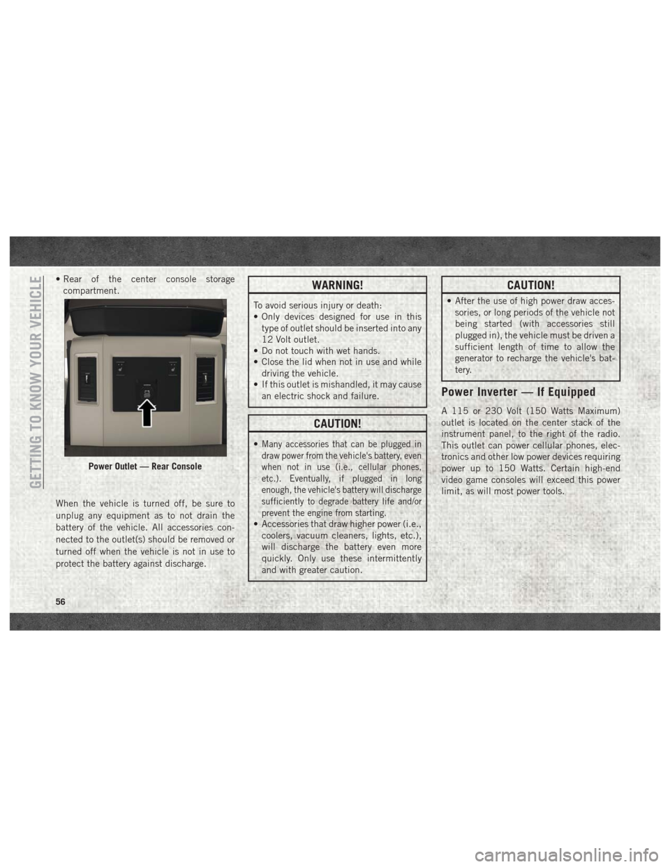
• Rear of the center console storagecompartment.
When the vehicle is turned off, be sure to
unplug any equipment as to not drain the
battery of the vehicle. All accessories con-
nected to the outlet(s) should be removed or
turned off when the vehicle is not in use to
protect the battery against discharge.WARNING!
To avoid serious injury or death:
• Only devices designed for use in this type of outlet should be inserted into any
12 Volt outlet.
• Do not touch with wet hands.
• Close the lid when not in use and while
driving the vehicle.
• If this outlet is mishandled, it may cause
an electric shock and failure.
CAUTION!
•Many accessories that can be plugged in
draw power from the vehicle's battery, even
when not in use (i.e., cellular phones,
etc.). Eventually, if plugged in long
enough, the vehicle's battery will discharge
sufficiently to degrade battery life and/or
prevent the engine from starting.
• Accessories that draw higher power (i.e.,coolers, vacuum cleaners, lights, etc.),
will discharge the battery even more
quickly. Only use these intermittently
and with greater caution.
CAUTION!
• After the use of high power draw acces-sories, or long periods of the vehicle not
being started (with accessories still
plugged in), the vehicle must be driven a
sufficient length of time to allow the
generator to recharge the vehicle's bat-
tery.
Power Inverter — If Equipped
A 115 or 230 Volt (150 Watts Maximum)
outlet is located on the center stack of the
instrument panel, to the right of the radio.
This outlet can power cellular phones, elec-
tronics and other low power devices requiring
power up to 150 Watts. Certain high-end
video game consoles will exceed this power
limit, as will most power tools.
Power Outlet — Rear Console
GETTING TO KNOW YOUR VEHICLE
56
Page 68 of 372

INSTRUMENT CLUSTER DISPLAY
Your vehicle may be equipped with an instru-
ment cluster display, which offers useful in-
formation to the driver. With the ignition in
the STOP/OFF mode, opening/closing of a
door will activate the display for viewing, and
display the total miles, or kilometers, in the
odometer. Your instrument cluster display is
designed to display important information
about your vehicle’s systems and features.
Using a driver interactive display located on
the instrument panel, your instrument clus-
ter display can show you how systems are
working and give you warnings when they are
not. The steering wheel mounted controls
allow you to scroll through the main menus
and submenus. You can access the specific
information you want and make selections
and adjustments.
Instrument Cluster Display
Controls
The instrument cluster display features a
driver-interactive display that is located in
the instrument cluster.
The instrument cluster display menu items
may consist of the following:
• Speedometer
• Vehicle Info
• Fuel Economy Info
• Trip A
• Trip B
• Audio
• Trailer Tow
• Stored Messages
• Screen Setup
• Vehicle Settings (Not Equipped with aUconnect touchscreen radio) The system allows the driver to select infor-
mation by pushing the following instrument
cluster display control buttons located on the
left side of the steering wheel:
• Push and release the
uparrow button to
scroll upward through the main menu
items, submenu screen, and vehicle set-
tings.
Instrument Cluster Display Controls
GETTING TO KNOW YOUR INSTRUMENT PANEL
66
Page 93 of 372
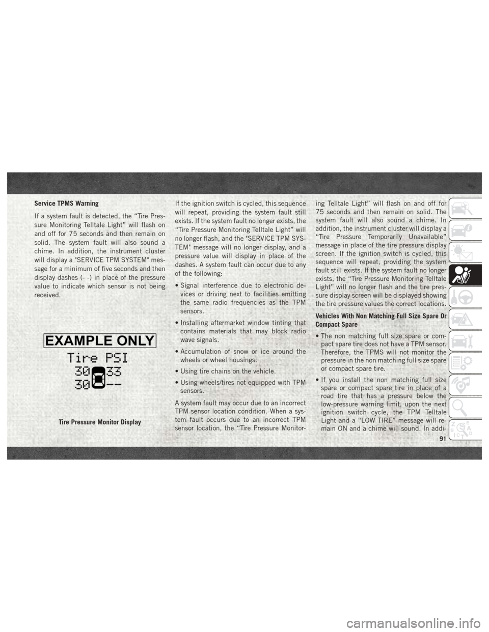
Service TPMS Warning
If a system fault is detected, the “Tire Pres-
sure Monitoring Telltale Light” will flash on
and off for 75 seconds and then remain on
solid. The system fault will also sound a
chime. In addition, the instrument cluster
will display a "SERVICE TPM SYSTEM" mes-
sage for a minimum of five seconds and then
display dashes (- -) in place of the pressure
value to indicate which sensor is not being
received.If the ignition switch is cycled, this sequence
will repeat, providing the system fault still
exists. If the system fault no longer exists, the
“Tire Pressure Monitoring Telltale Light” will
no longer flash, and the "SERVICE TPM SYS-
TEM" message will no longer display, and a
pressure value will display in place of the
dashes. A system fault can occur due to any
of the following:
• Signal interference due to electronic de-
vices or driving next to facilities emitting
the same radio frequencies as the TPM
sensors.
• Installing aftermarket window tinting that contains materials that may block radio
wave signals.
• Accumulation of snow or ice around the wheels or wheel housings.
• Using tire chains on the vehicle.
• Using wheels/tires not equipped with TPM sensors.
A system fault may occur due to an incorrect
TPM sensor location condition. When a sys-
tem fault occurs due to an incorrect TPM
sensor location, the “Tire Pressure Monitor- ing Telltale Light” will flash on and off for
75 seconds and then remain on solid. The
system fault will also sound a chime. In
addition, the instrument cluster will display a
“Tire Pressure Temporarily Unavailable”
message in place of the tire pressure display
screen. If the ignition switch is cycled, this
sequence will repeat, providing the system
fault still exists. If the system fault no longer
exists, the “Tire Pressure Monitoring Telltale
Light” will no longer flash and the tire pres-
sure display screen will be displayed showing
the tire pressure values the correct locations.
Vehicles With Non Matching Full Size Spare Or
Compact Spare
• The non matching full size spare or com-
pact spare tire does not have a TPM sensor.
Therefore, the TPMS will not monitor the
pressure in the non matching full size spare
or compact spare tire.
• If you install the non matching full size spare or compact spare tire in place of a
road tire that has a pressure below the
low-pressure warning limit, upon the next
ignition switch cycle, the TPM Telltale
Light and a “LOW TIRE” message will re-
main ON and a chime will sound. In addi-
Tire Pressure Monitor Display
91
Page 94 of 372
tion, the graphic in the instrument cluster
will still display a pressure value in a differ-
ent color.
• After driving the vehicle for up to 20 min- utes above 15 mph (24 km/h), the TPM
Telltale Light will flash on and off for
75 seconds and then remain on solid. In
addition, the instrument cluster will display
a "SERVICE TPM SYSTEM" message for a
minimum of five seconds and then display
dashes (- -) in place of the pressure value.
• For each subsequent ignition switch cycle, a chime will sound, the TPM Telltale Light
will flash on and off for 75 seconds and
then remain on solid, and the instrument
cluster will display a "SERVICE TPM SYS-
TEM" message for a minimum of five sec-
onds and then display dashes (- -) in place
of the pressure value.
•
Once you repair or replace the original road
tire and reinstall it on the vehicle in place of
the non matching full size spare or compact
spare, the TPMS will update automatically.
In addition, the TPM Telltale Light will turn
OFF and the graphic in the instrument clus-
ter will display a new pressure value instead
of dashes (- -), as long as no tire pressure is below the low-pressure warning limit in any
of the four active road tires. The vehicle may
need to be driven for up to 20 minutes above
15 mph (24 km/h) in order for the TPMS to
receive this information.
Tire Pressure Information System (TPIS)
3500 Series Trucks
Your vehicle may be equipped with a Tire
Pressure Information System (TPIS).
The Tire Pressure Information System (TPIS)
uses wireless technology with wheel rim
mounted electronic sensors to transmit tire
pressure levels. Sensors mounted to each
wheel as part of the valve stem transmit tire
pressure readings to the receiver module.
NOTE:
It is particularly important for you to check
the tire pressure in all of the tires on your
vehicle monthly and to maintain the proper
pressure.
The TPIS consists of the following compo-
nents:
• Receiver module
• Four TPM sensors (Single Rear Wheel
(SRW) applications)
• Six TPM sensors (Dual Rear Wheel (DRW) applications)
• Pressure display in the instrument cluster
The TPIS system will display all four (Single
Rear Wheel (SRW) applications) or six (Dual
Rear Wheel (DRW) applications) tire pressure
values in the instrument cluster display.
If a system fault is detected, the instrument
cluster will display a "SERVICE TPM SYS-
TEM" message for a minimum of five seconds
and then display dashes (- -) in place of the
pressure value to indicate which sensor is not
being received.
If the ignition switch is cycled, this sequence
will repeat, providing the system fault still
exists. If the system fault no longer exists, the
"SERVICE TPM SYSTEM" message will no
longer be displayed, and a pressure value will
display in place of the dashes. A system fault
can occur due to any of the following:
•
Signal interference due to electronic devices
or driving next to facilities emitting the same
radio frequencies as the TPM sensors.
SAFETY
92
Page 95 of 372
• Installing aftermarket window tinting thatcontains materials that may block radio
wave signals.
• Accumulation of snow or ice around the wheels or wheel housings.
• Using tire chains on the vehicle.
• Using wheels/tires not equipped with TPM sensors.
General Information
This device complies with Part 15 of the FCC
rules and RSS 210 of Industry Canada. Op-
eration is subject to the following conditions:
1. This device may not cause harmful
interference.
2. This device must accept any interference received, including interference that may
cause undesired operation.
NOTE:
Changes or modifications not expressly ap-
proved by the party responsible for compli-
ance could void the user’s authority to oper-
ate the equipment.
OCCUPANT RESTRAINT SYSTEMS
Some of the most important safety features in
your vehicle are the restraint systems:
Occupant Restraint Systems
Features
• Seat Belt Systems
• Supplemental Restraint Systems (SRS) Air Bags
• Child Restraints
Some of the safety features described in this
section may be standard equipment on some
models, or may be optional equipment on
others. If you are not sure, ask your autho-
rized dealer.
Important Safety Precautions
Please pay close attention to the information
in this section. It tells you how to use your
restraint system properly, to keep you and
your passengers as safe as possible. Here are some simple steps you can take to
minimize the risk of harm from a deploying
air bag:
1. Children 12 years old and under should
always ride buckled up in a vehicle with a
rear seat.
2. If a child from 2 to 12 years old (not in a rear-facing child restraint) must ride in
the front passenger seat, move the seat as
far back as possible and use the proper
child restraint (refer to “Child Restraints”
in this section for further information).
3. Children that are not big enough to wear the vehicle seat belt properly (refer to
“Child Restraints” in this section for fur-
ther information) should be secured in a
vehicle with a rear seat in child restraints
or belt-positioning booster seats. Older
children who do not use child restraints or
belt-positioning booster seats should ride
properly buckled up in a vehicle with a
rear seat.
4. Never allow children to slide the shoulder belt behind them or under their arm.
93
Page 109 of 372
Because air bag sensors measure vehicle de-
celeration over time, vehicle speed and dam-
age by themselves are not good indicators of
whether or not an air bag should have de-
ployed.
Seat belts are necessary for your protection in
all collisions, and also are needed to help
keep you in position, away from an inflating
air bag.
When the ORC detects a collision requiring
the front air bags, it signals the inflator units.
A large quantity of non-toxic gas is generated
to inflate the front air bags.
The steering wheel hub trim cover and the
upper right side of the instrument panel
separate and fold out of the way as the air
bags inflate to their full size. The front air
bags fully inflate in less time than it takes to
blink your eyes. The front air bags then
quickly deflate while helping to restrain the
driver and front passenger.Knee Impact Bolsters
The Knee Impact Bolsters help protect the
knees of the driver and front passenger, and
position the front occupants for improved
interaction with the front air bags.
WARNING!
• Do not drill, cut, or tamper with the kneeimpact bolsters in any way.
• Do not mount any accessories to the
knee impact bolsters such as alarm
lights, stereos, citizen band radios, etc.
Supplemental Side Air Bags
Ram 1500
Supplemental Seat-Mounted Side Air Bags
(SABs)
This vehicle is equipped with Supplemental
Seat-Mounted Side Air Bags (SABs).
Supplemental Seat-Mounted Side Air Bags
(SABs) are located in the outboard side of the
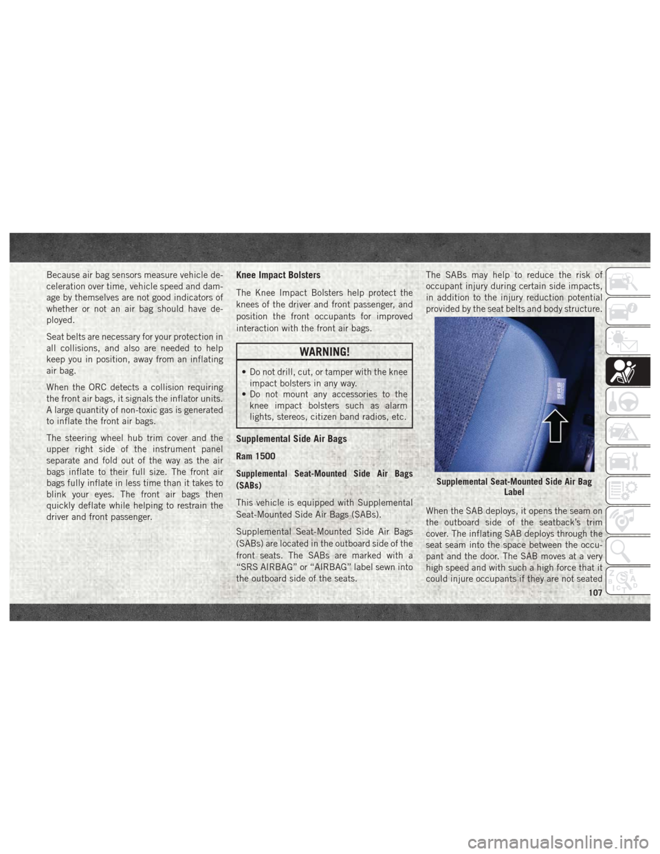
front seats. The SABs are marked with a
“SRS AIRBAG” or “AIRBAG” label sewn into
the outboard side of the seats. The SABs may help to reduce the risk of
occupant injury during certain side impacts,
in addition to the injury reduction potential
provided by the seat belts and body structure.
When the SAB deploys, it opens the seam on
the outboard side of the seatback’s trim
cover. The inflating SAB deploys through the
seat seam into the space between the occu-
pant and the door. The SAB moves at a very
high speed and with such a high force that it
could injure occupants if they are not seated
Supplemental Seat-Mounted Side Air Bag
Label
107
Page 173 of 372
if the vehicle speed exceeds 66 mph
(106 km/h). The vehicle will return to NRH
from Aero Mode if the vehicle speed re-
mains between 30 mph (48 km/h) and
35 mph (56 km/h) for greater than 20 sec-
onds or if the vehicle speed falls below
30 mph (48 km/h).
NOTE:
Automatic Aero Mode may be disabled
through vehicle settings in the instrument
cluster when equipped with Uconnect 3.0, or
your Uconnect Radio when equipped with
Uconnect 5.0, 8.4A, or 8.4AN.
• Entry/Exit Mode (Lowers the vehicle approxi-
mately 2 in (51 mm)) - This position lowers
the vehicle for easier passenger entry and
exit as well as lowering the rear of the
vehicle for easier loading and unloading of
cargo. To enter Entry/Exit Mode, push the
“Down” button once from the NHR while
the vehicle speed is below 33 mph (53 km/
h). Once the vehicle speed goes below
15 mph (24 km/h) the vehicle height will
begin to lower. If the vehicle speed remains
between 15 mph (24 km/h) and 25 mph
(40 km/h) for greater than 60 seconds, or the vehicle speed exceeds 25 mph
(40 km/h) the Entry/Exit change will be
cancelled. To return to Normal Height
Mode, push the “Up” button once while in
Entry/Exit or drive the vehicle over 15 mph
(24 km/h). Entry/Exit mode may not be
available due to vehicle payload, an instru-
ment cluster message will be displayed
when this occurs. Refer to “Instrument
Cluster Display” in “Getting To Know Your
Instrument Panel” in the Owner’s Manual
for further information.
Air Suspension Modes
The Air Suspension system has multiple
modes to protect the system in unique situa-
tions:
AERO Mode
To improve aerodynamics, the air suspension
system has a feature which will put the ve-
hicle into AERO height automatically. Refer
to “Instrument Cluster Display” in “Getting
To Know Your Instrument Panel” in the Own-
er’s Manual for further information.
NOTE:
This mode is intended to be enabled with
engine running.
Tire/Jack Mode
To assist with changing a tire, the air suspen-
sion system has a feature which allows the
automatic leveling to be disabled. Refer to
“Instrument Cluster Display” in “Getting To
Know Your Instrument Panel” in the Owner’s
Manual for further information.
NOTE:
This mode is intended to be enabled with
engine running.
Transport Mode
For towing your vehicle with four wheels off
the ground, the air suspension system has a
feature which will put the vehicle into Entry/
Exit height and disable the automatic load
leveling system. Refer to “Instrument Cluster
Display” in “Getting To Know Your Instru-
ment Panel” in the Owner’s Manual for fur-
ther information.
171
Page 175 of 372
•Normal Ride Height (NRH) – This is the stan-
dard position of the suspension and is
meant for normal driving.
• Off-Road (OR) (Raises the vehicle approxi-
mately 1 in (26 mm)) – This position is
intended for off-roading use only where
maximum ground clearance is required. To
enter OR, push the “Up” button once from
the NRH position while vehicle speed is
below 20 mph (32 km/h). While in OR, if
the vehicle speed exceeds 25 mph
(40 km/h) the vehicle height will be auto-
matically lowered to NRH. Off-Road may
not be available due to vehicle payload, an
instrument cluster display message will be
shown when this occurs. Refer to “Instru-
ment Cluster Display” in “Getting To Know
Your Instrument Panel” in your Owner’s
Manual for further information.
• Aero Mode (Lowers the vehicle approximately
.6 in (15 mm)) – This position provides
improved aerodynamics by lowering the ve-
hicle. The vehicle will automatically enter
Aero Mode when the vehicle speed remains
between 62 mph (100 km/h) and 66 mph
(106 km/h) for greater than 20 seconds or
if the vehicle speed exceeds 66 mph (106 km/h). The vehicle will return to NRH
from Aero Mode if the vehicle speed re-
mains between 30 mph (48 km/h) and
35 mph (56 km/h) for greater than 20 sec-
onds or if the vehicle speed falls below
30 mph (48 km/h).
To enter Aero Mode manually push the down
button once from NRH at any vehicle speed.
To return to NRH push the up button once
while vehicle speed is less than 56 mph
(90 km/h).
NOTE:
Automatic Aero Mode may be disabled
through vehicle settings on your Uconnect
Radio when equipped with UConnect 5.0,
8.4A, or 8.4AN. Refer to “Uconnect Set-
tings” in “Multimedia” in your Owner’s
Manual for further information.
• Entry/Exit Mode (Lowers the vehicle approxi-
mately 3 in (73 mm)) – This position lowers
the vehicle for easier passenger entry and
exit as well as lowering the rear of the
vehicle for easier loading and unloading of
cargo. To enter Entry/Exit Mode, push the
“Down” button twice from the NRH while
the vehicle speed is below 33 mph (53 km/ h). Once the vehicle speed goes below
15 mph (24 km/h) the vehicle height will
begin to lower. If the vehicle speed remains
between 15 mph (24 km/h) and 25 mph
(40 km/h) for greater than 60 seconds, or
the vehicle speed exceeds 25 mph
(40 km/h) the Entry/Exit change will be
cancelled. To return to Normal Height
Mode, push the “Up” button twice while in
Entry/Exit or drive the vehicle over 15 mph
(24 km/h). Entry/Exit mode may not be
available due to vehicle payload, an instru-
ment cluster display message will be shown
when this occurs. Refer to “Instrument
Cluster Display” in “Getting To Know Your
Instrument Panel” in your Owner’s Manual
for further information.
Air Suspension Modes
The Air Suspension system has multiple
modes to protect the system in unique situa-
tions:
AERO Mode
To improve aerodynamics, the air suspension
system has a feature which will put the ve-
hicle into AERO height automatically. Refer
173