radio Ram 3500 2018 Owner's Manual
[x] Cancel search | Manufacturer: RAM, Model Year: 2018, Model line: 3500, Model: Ram 3500 2018Pages: 372, PDF Size: 7.1 MB
Page 177 of 372
Normal Ride Height (NRH)– This is the stan-
dard position of the suspension and is meant
for normal driving. It will automatically adjust
to maintain the rear ride height as conditions
change.
Alternate Trailer Height (ATH) – Lowers the
vehicle approximately 1 in (25 mm) for a
level truck, to be used as required while
trailer towing. It will automatically adjust to
maintain the rear ride height as conditions
change.
Trailer Decoupling/Unloading - The air suspen-
sion system will load level (lower/exhaust
only) for up to 10 minutes after the vehicle is
turned off. This allows for easy removal of a trailer and/or load from the back of the truck
by maintaining the ride height. After 10 min-
utes you will need to turn the ignition to the
run position for the air suspension to main-
tain ride height. If the air suspension system
is disabled using the settings menu (Tire Jack
Mode, Transport Mode or Alignment Mode)
the system will remain disabled when the
vehicle is turned off. Reactivating the air
suspension can be accomplished via the set-
tings menu or driving the vehicle above
5 mph (8 km/h) for Tire Jack Mode or Align-
ment Mode and 16 mph (26 km/h) for Trans-
port Mode.
NOTE:
• Most 3500 models will not lower to Alter-
nate Trailer Height (ATH) when unloaded.
• Refer to “Trailer Towing” in “Starting And Operating” for further information.
Ignition OFF Behavior
For a predetermined amount of time after the
ignition is off the air suspension may adjust
to maintain a proper appearance.
Refer to your Owner’s Manual for further
information.
WARNING!
The air suspension system uses a high
pressure volume of air to operate the sys-
tem. To avoid personal injury or damage to
the system, see your authorized dealer for
service.
Air Suspension Modes
The air suspension system has multiple
modes to protect the system in unique situa-
tions:
Tire/Jack Mode
To assist with changing a tire, the air suspen-
sion system has a feature which allows the
automatic leveling to be disabled. This mode
is intended to be enabled with engine run-
ning. Refer to “Instrument Cluster Display”
in “Getting To Know Your Instrument Panel”
or “Uconnect Settings” in “Multimedia” if
equipped with a touch screen radio, in your
Owner’s Manual for further information.
NOTE:
This mode is intended to be enabled with
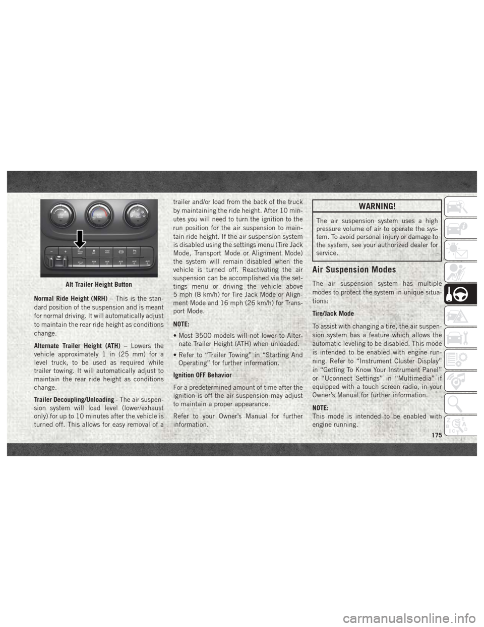
engine running.Alt Trailer Height Button
175
Page 178 of 372
Transport Mode
To assist with flat bed towing, the air suspen-
sion system has a feature which will put the
vehicle below Normal Ride Height (NRH) and
disable the automatic load leveling system.
This mode is intended to be enabled with
engine running. Refer to “Instrument Cluster
Display” in “Getting To Know Your Instru-
ment Panel” or “Uconnect Settings” in “Mul-
timedia” if equipped with a touch screen
radio, in your Owner’s Manual for further
information.
NOTE:
This mode is intended to be enabled with
engine running.
Wheel Alignment Mode
Before performing a wheel alignment this
mode must be enabled. Refer to “Instrument
Cluster Display” in “Getting To Know Your
Instrument Panel” or “Uconnect Settings” in
“Multimedia” if equipped with a touch
screen radio, in your Owner’s Manual for
further information.NOTE:
This mode is intended to be enabled with
engine running.
Protection Strategy
In order to “protect” the air suspension sys-
tem, the vehicle will disable load leveling as
required (suspension overloaded, battery
charge low, etc.). Load leveling will automati-
cally resume as soon as system operation
requirements are met. See your authorized
dealer if system does not resume.
SPEED CONTROL
When engaged, the Speed Control takes over
accelerator operations at speeds greater than
25 mph (40 km/h).
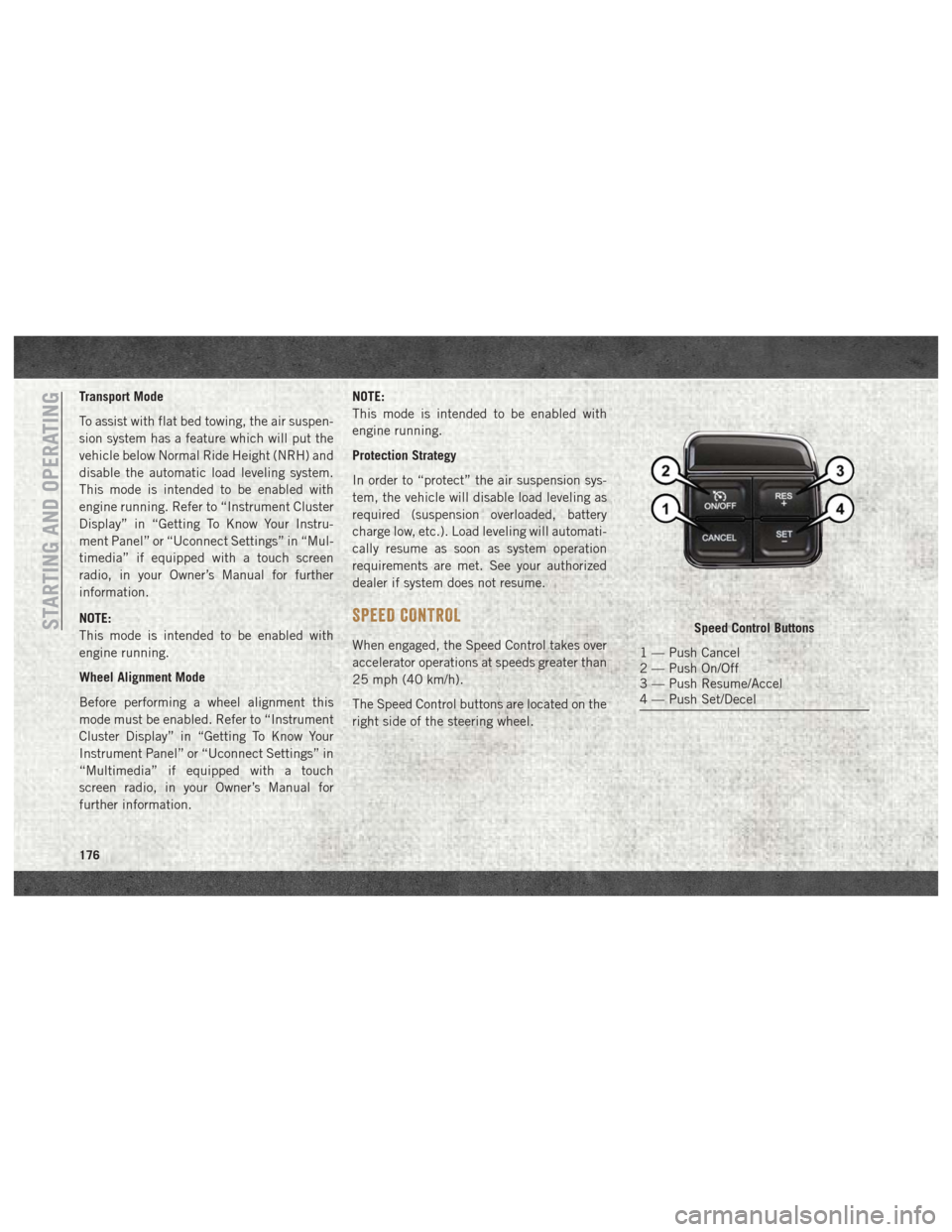
The Speed Control buttons are located on the
right side of the steering wheel.
Speed Control Buttons
1 — Push Cancel
2 — Push On/Off
3 — Push Resume/Accel
4 — Push Set/Decel
STARTING AND OPERATING
176
Page 204 of 372
HAZARD WARNING FLASHERS
The Hazard Warning flasher switch is located
on the upper switch bank just below the
radio.
Push the switch to turn on the Hazard Warn-
ing flasher. When the switch is activated, all
directional turn signals will flash on and off to
warn oncoming traffic of an emergency. Push
the switch a second time to turn off the
Hazard Warning flashers.
This is an emergency warning system and it
should not be used when the vehicle is in
motion. Use it when your vehicle is disabled
and it is creating a safety hazard for other
motorists.
When you must leave the vehicle to seek
assistance, the Hazard Warning flashers will
continue to operate even though the ignition
is placed in the OFF position.
NOTE:
With extended use the Hazard Warning flash-
ers may wear down your battery.
BULB REPLACEMENT
Replacement Bulbs
All of the inside bulbs are brass or glass-
wedge base. Aluminum base bulbs are not
approved.
Interior Bulbs
Bulb Number
Overhead Console
Lamps TS 212–9
Dome Lamp 7679
For lighted switches, see your authorized
dealer for replacement instructions.
Exterior Bulbs
Bulb Number
Base Quad Head-
lamp – Low Beam H11LL
Base Quad Head-
lamp – High Beam 9005LL
Front Turn Signal
Lamp (Base Quad
Headlamp) 3157NA
Bulb Number
Premium Bi Halogen
Projector Headlamp -
Low Beam 9005Sl+
Premium Bi Halogen
Projector Headlamp -
High Beam 9005LL
Front Turn Signal
Lamp (Premium
Headlamp) LED (Serviced at au-
thorized dealer)
Fog Lamp (Horizontal
shape) 9145
Fog Lamp (Vertical
shape) 9006
Center High Mounted
Stop Lamp (CHMSL) 921K
Rear Cargo Lamp 921
LED Center High
Mounted Stop Lamp
(CHMSL)/Cargo
Lamp LED (Serviced at au-
thorized dealer)
Cab Roof Marker
Lamps 194NA
Base Rear Tail/Turn
and Stop Lamp 3157K
Premium Rear Tail/
Turn and Stop Lamp LED (Serviced at au-
thorized dealer)
IN CASE OF EMERGENCY
202
Page 221 of 372
NOTE:
The positive battery post may be covered with
a protective cap if equipped. Lift up on the
cap to gain access to the positive battery
post. Do not jump off fuses. Only jump di-
rectly off positive post which has a positive
(+)symbol on or around the post.
WARNING!
• Take care to avoid the radiator cooling
fan whenever the hood is raised. It can
start anytime the ignition switch is ON.
You can be injured by moving fan blades.
• Remove any metal jewelry such as rings,
watch bands and bracelets that could
make an inadvertent electrical contact.
You could be seriously injured.
• Batteries contain sulfuric acid that can
burn your skin or eyes and generate
hydrogen gas which is flammable and
explosive. Keep open flames or sparks
away from the battery.
1. Apply the parking brake, shift the auto- matic transmission into PARK and turn
the ignition to LOCK. 2. Turn off the heater, radio, and all unnec-
essary electrical accessories.
3. If using another vehicle to jump start the battery, park the vehicle within the jumper
cables reach, apply the parking brake and
make sure the ignition is OFF.
WARNING!
Do not allow vehicles to touch each other
as this could establish a ground connec-
tion and personal injury could result.
Jump Starting Procedure
WARNING!
Failure to follow this jump starting proce-
dure could result in personal injury or
property damage due to battery explosion.
CAUTION!
Failure to follow these procedures could
result in damage to the charging system of
the booster vehicle or the discharged ve-
hicle.
Connecting The Jumper Cables
1. Connect the positive (+)end of the jumper
cable to the positive (+)post of the dis-
charged vehicle.
NOTE:
Do not jump off fuses. Only jump directly off
positive post.
2. Connect the opposite end of the positive (+) jumper cable to the positive (+)post of
the booster battery.
3. Connect the negative (-)end of the jumper
cable to the negative (-)post of the
booster battery.
4. Connect the opposite end of the negative (-)jumper cable to a good engine ground
(exposed metal part of the discharged
vehicle’s engine) away from the battery
and the fuel injection system.
WARNING!
Do not connect the jumper cable to the
negative (-) post of the discharged battery.
The resulting electrical spark could cause
the battery to explode and could result in
219
Page 291 of 372
MULTIMEDIA
CYBERSECURITY..............291
RADIO 3.0 ................. .292
Clock Setting.................293
Audio Setting .................293
Radio Operation ...............293
Disc Operation — If Equipped ......293
USB/Audio Jack (AUX) Manual
Operation ...................294
UCONNECT 3.0 ...............295
Clock Setting.................296
Audio Setting .................296
Radio Operation ...............296
Disc Operation — If Equipped ......296
USB/Audio Jack (AUX) Manual
Operation ...................297
UCONNECT 3 WITH 5-INCH DISPLAY . .298
Controls On The Front Panel .......298
Clock Setting .................299
Equalizer, Balance And Fade .......299
Radio Mode ..................300
Media Mode .................301 Bluetooth Source
..............304
UCONNECT 4C/4C NAV WITH 8.4-INCH
DISPLAY.................. .306
Uconnect 4C/4C NAV At A Glance . . . .306
Personalized Menu Bar...........309
Radio .....................310
Android Auto .................310
Apple CarPlay Integration .........314
SIRIUSXM GUARDIAN — IF EQUIPPED.316
SiriusXM Guardian — If Equipped
(Available on Uconnect 4C NAV) .....316
SiriusXM Guardian Activation ......317
Download The Uconnect App .......318
Renewing Subscriptions (Uconnect 4C
NAV)......................318
Maintaining Your SiriusXM Guardian
Account ...................318
Built-In Features ..............318
SiriusXM Guardian Remote Features . .321
UCONNECT SETTINGS ...........324
TIPS CONTROLS AND GENERAL
INFORMATION ............... .325
Steering Wheel Audio Controls ......325
Reception Conditions ............325
Care And Maintenance ...........325
Anti-Theft Protection ............325
IPOD/USB/MEDIA PLAYER CONTROL . .325
Audio Jack (AUX)..............326
USB Port ...................326
Bluetooth Streaming Audio ........326
NAVIGATION................ .327
Changing The Navigation Voice Prompt
Volume....................327
Finding Points Of Interest .........329
Finding A Place By Spelling The Name .329
One-Step Voice Destination Entry . . . .329
Setting Your Home Location ........329
Home .....................330
Adding A Stop ................330
Taking A Detour ...............330
SiriusXM Traffic Plus (4C NAV) .....330
SiriusXM Travel Link (4C NAV) ......331
UCONNECT PHONE............332
MULTIMEDIA
289
Page 292 of 372
Uconnect Phone (Bluetooth Hands Free
Calling)....................332
Pairing (Wirelessly Connecting) Your Mobile
Phone To The Uconnect System .....334
Common Phone Commands
(Examples) ..................337
Mute (Or Unmute) Microphone During
Call ......................337
Transfer Ongoing Call Between Handset
And Vehicle .................337
Phonebook ..................337
Voice Command Tips ............338
Changing The Volume ............338
Using Do Not Disturb ...........338 Incoming Text Messages
..........338
Helpful Tips And Common Questions To
Improve Bluetooth Performance With Your
Uconnect System ..............340
UCONNECT VOICE RECOGNITION QUICK
TIPS..................... .340
Introducing Uconnect...........340
Get Started .................340
Basic Voice Commands ...........341
Radio .....................342
Media .....................343
Phone .....................343 Climate (4C/4C NAV)
............344
Navigation (4C NAV) ............344
SiriusXM Guardian (4C NAV) — If
Equipped ...................345
Register (4C NAV) ..............346
Vehicle Health Report/Alert (4C NAV) . .346
Mobile App (4C NAV) ............346
SiriusXM Travel Link (4C NAV) ......346
Apple CarPlay — If Equipped .......347
Android Auto — If Equipped .......348
General Information .............348
Additional Information ...........349MULTIMEDIA
290
Page 294 of 372
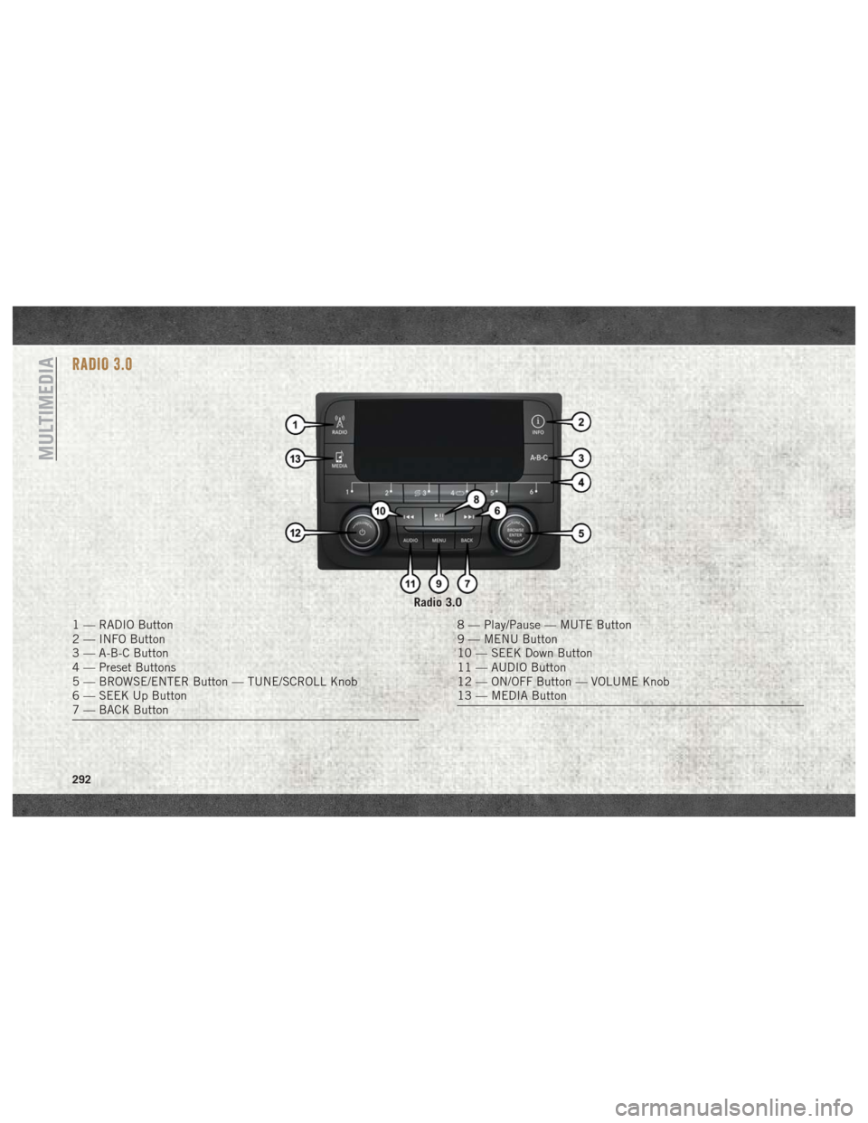
RADIO 3.0
Radio 3.0
1 — RADIO Button
2 — INFO Button
3 — A-B-C Button
4 — Preset Buttons
5 — BROWSE/ENTER Button — TUNE/SCROLL Knob
6 — SEEK Up Button
7 — BACK Button8 — Play/Pause — MUTE Button
9 — MENU Button
10 — SEEK Down Button
11 — AUDIO Button
12 — ON/OFF Button — VOLUME Knob
13 — MEDIA Button
MULTIMEDIA
292
Page 295 of 372
Clock Setting
1. Push the Menu button at the bottom ofthe radio, and push the Enter/Browse but-
ton for System Settings. Next, select the
Time and Format setting and then select
Set Time by pushing the Enter/Browse
button.
2. Adjust the hours or minutes by turning the Tune/Scroll knob, then pushing the Enter/
Browse button to move to the next entry.
You can also select 12hr or 24hr format by
turning the Tune/Scroll knob, then push-
ing the Enter/Browse button on the de-
sired selection.
3. Once the time is set, press the “Ok” button to exit the time screen.
Audio Setting
• Push the AUDIO button on the radio face-plate.
• The Audio Menu shows the following op- tions for you to customize your audio
settings. Treble, Mid, Bass, Fade, Balance, Speed Ad-
justed Volume, Loudness and AUX Offset
• Select the desired setting to adjust, then
push the ENTER/BROWSE button. Turn the
TUNE/SCROLL knob to adjust the setting +
or - . Push the “Back” button when done.
Radio Operation
Seek Up/Down Buttons
• Push the up or down button to seek throughradio stations in AM, FM or SXM bands.
• Hold either button to bypass stations with- out stopping.
Store Radio Presets Manually
The presets are available for all Radio Modes,
and are activated by pushing any of the six
preset buttons. The Radio stores up to
18 presets in each of the Radio modes. Push
the A-B-C button on the faceplate to select
the A, B, or C preset list.
To store a radio preset manually, follow the
steps below:
1. Tune to the desired station. 2. Push and hold the desired numbered but-
ton for more than two seconds, or until you
hear a confirmation beep.
Disc Operation — If Equipped
Your vehicle may have a remote CD player
located in the lower center console storage
bin, or in the lower center bench seat bin.
• CD/Disc Mode is entered by either insertinga CD/Disc or by pushing the MEDIA button
located on the side of the display. Once in
Media Mode, select “Disc.”
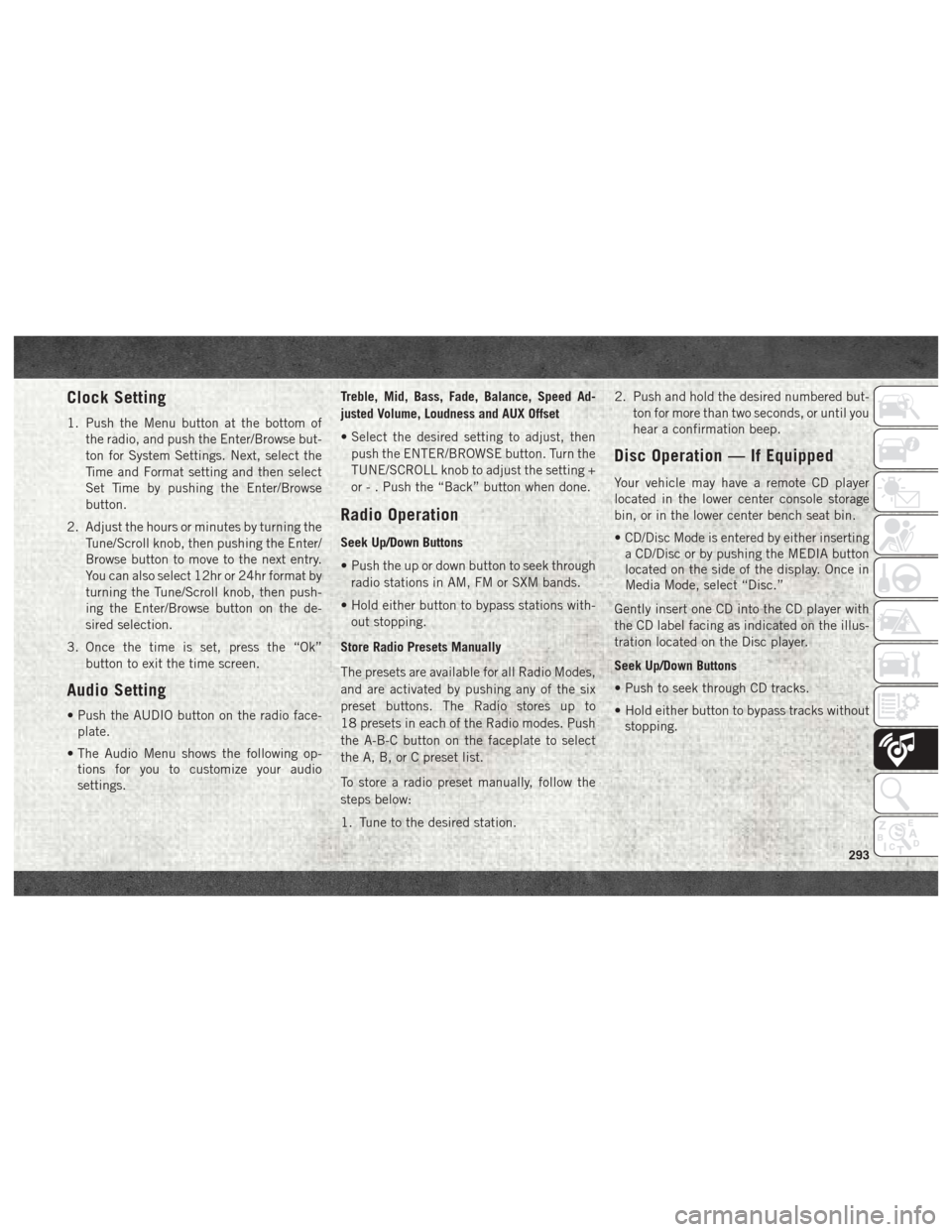
Gently insert one CD into the CD player with
the CD label facing as indicated on the illus-
tration located on the Disc player.
Seek Up/Down Buttons
• Push to seek through CD tracks.
• Hold either button to bypass tracks without stopping.
293
Page 296 of 372
USB/Audio Jack (AUX) Manual
Operation
To select a specific audio source, push the
MEDIA button on the faceplate and select
from the following modes:
USB/iPod
• USB/iPod Mode is entered by either insert-ing a USB Jump Drive or iPod cable into the
USB port or by pushing the MEDIA button
located left of the display.
Audio Jack (AUX)
• The AUX allows a device such as an MP3 player or an iPod to be plugged into
the radio and utilize the vehicle’s audio
system, using a 3.5 mm audio cable, to
amplify the source and play through the
vehicle’s speakers.
• The functions of the device are controlled using the device buttons, not the buttons
on the radio. The volume may be controlled
using the radio or the device.
MULTIMEDIA
294
Page 297 of 372
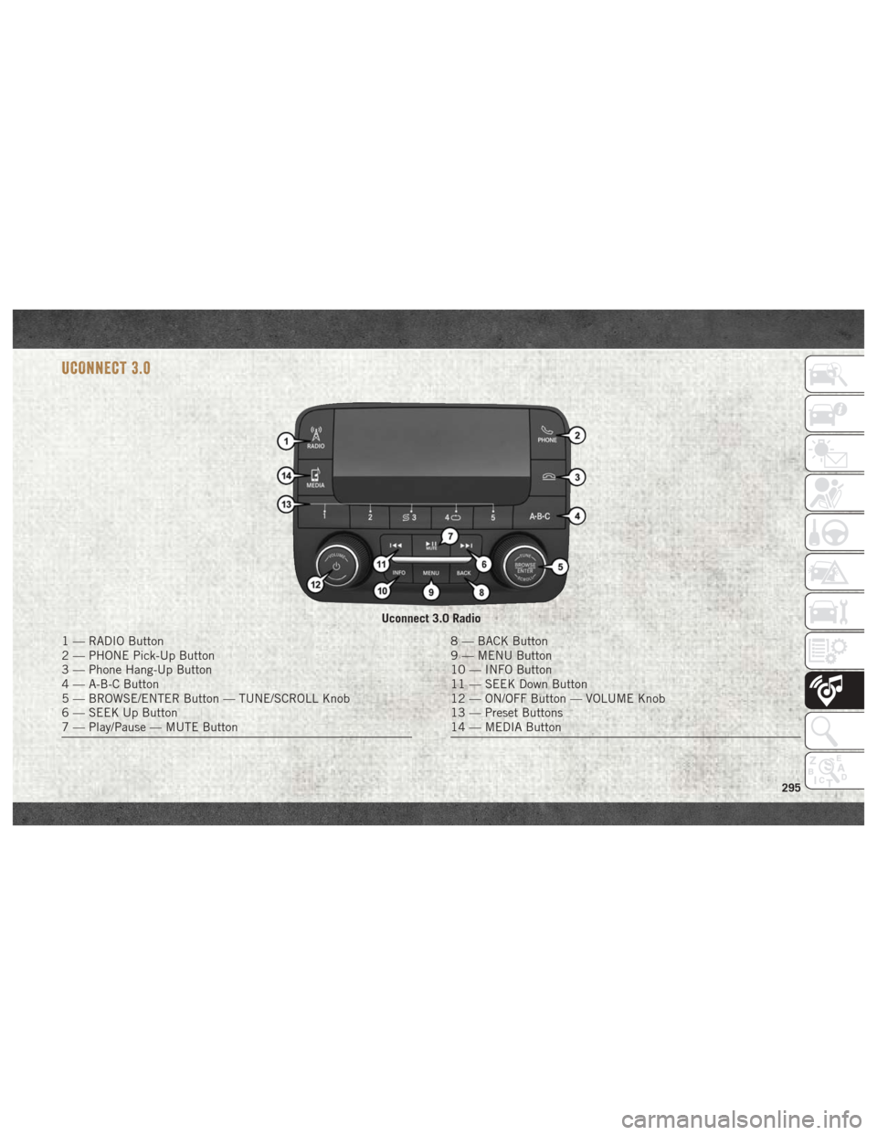
UCONNECT 3.0
Uconnect 3.0 Radio
1 — RADIO Button
2 — PHONE Pick-Up Button
3 — Phone Hang-Up Button
4 — A-B-C Button
5 — BROWSE/ENTER Button — TUNE/SCROLL Knob
6 — SEEK Up Button
7 — Play/Pause — MUTE Button8 — BACK Button
9 — MENU Button
10 — INFO Button
11 — SEEK Down Button
12 — ON/OFF Button — VOLUME Knob
13 — Preset Buttons
14 — MEDIA Button
295