service indicator Ram 3500 2020 User Guide
[x] Cancel search | Manufacturer: RAM, Model Year: 2020, Model line: 3500, Model: Ram 3500 2020Pages: 568
Page 139 of 568
GETTING TO KNOW YOUR INSTRUMENT PANEL137
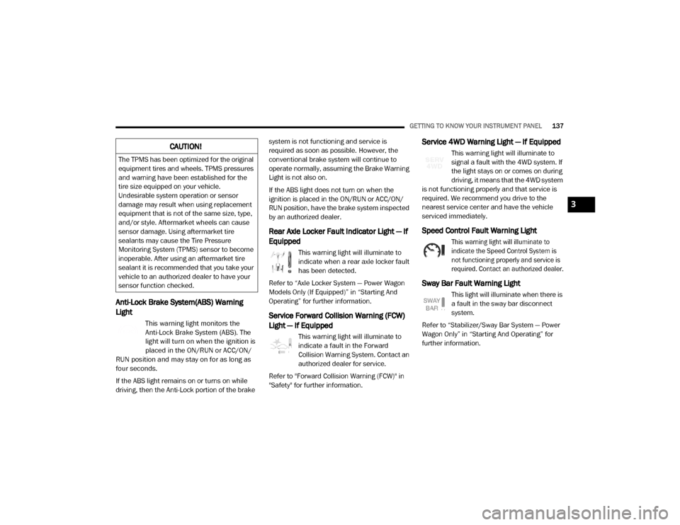
Anti-Lock Brake System(ABS) Warning
Light
This warning light monitors the
Anti-Lock Brake System (ABS). The
light will turn on when the ignition is
placed in the ON/RUN or ACC/ON/
RUN position and may stay on for as long as
four seconds.
If the ABS light remains on or turns on while
driving, then the Anti-Lock portion of the brake system is not functioning and service is
required as soon as possible. However, the
conventional brake system will continue to
operate normally, assuming the Brake Warning
Light is not also on.
If the ABS light does not turn on when the
ignition is placed in the ON/RUN or ACC/ON/
RUN position, have the brake system inspected
by an authorized dealer.
Rear Axle Locker Fault Indicator Light — If
Equipped
This warning light will illuminate to
indicate when a rear axle locker fault
has been detected.
Refer to “Axle Locker System — Power Wagon
Models Only (If Equipped)” in “Starting And
Operating” for further information.
Service Forward Collision Warning (FCW)
Light — If Equipped
This warning light will illuminate to
indicate a fault in the Forward
Collision Warning System. Contact an
authorized dealer for service.
Refer to "Forward Collision Warning (FCW)" in
"Safety" for further information.
Service 4WD Warning Light — If Equipped
This warning light will illuminate to
signal a fault with the 4WD system. If
the light stays on or comes on during
driving, it means that the 4WD system
is not functioning properly and that service is
required. We recommend you drive to the
nearest service center and have the vehicle
serviced immediately.
Speed Control Fault Warning Light
This warning light will illuminate to
indicate the Speed Control System is
not functioning properly and service is
required. Contact an authorized dealer.
Sway Bar Fault Warning Light
This light will illuminate when there is
a fault in the sway bar disconnect
system.
Refer to “Stabilizer/Sway Bar System — Power
Wagon Only” in “Starting And Operating” for
further information.
CAUTION!
The TPMS has been optimized for the original
equipment tires and wheels. TPMS pressures
and warning have been established for the
tire size equipped on your vehicle.
Undesirable system operation or sensor
damage may result when using replacement
equipment that is not of the same size, type,
and/or style. Aftermarket wheels can cause
sensor damage. Using aftermarket tire
sealants may cause the Tire Pressure
Monitoring System (TPMS) sensor to become
inoperable. After using an aftermarket tire
sealant it is recommended that you take your
vehicle to an authorized dealer to have your
sensor function checked.
3
20_DJD2_OM_EN_USC_t.book Page 137
Page 142 of 568

140GETTING TO KNOW YOUR INSTRUMENT PANEL
Low Diesel Exhaust Fluid (DEF) Indicator
Light — If Equipped
The Low Diesel Exhaust Fluid (DEF)
Indicator will illuminate if the vehicle
is low on Diesel Exhaust Fluid (DEF).
Refer to “Starting And Operating” for
further information.
Wait To Start Light — If Equipped
This indicator light will illuminate for
approximately two seconds when the
ignition is turned to the RUN position.
Its duration may be longer based on
colder operating conditions. Vehicle will not
initiate start until telltale is no longer displayed.
Refer to “Starting The Engine” in “Starting And
Operating” for further information.
NOTE:
The “Wait To Start” telltale may not illuminate if
the intake manifold temperature is warm
enough.
Water In Fuel Indicator Light — If Equipped
The “Water In Fuel Indicator Light” will
illuminate when there is water
detected in the fuel filter. If this light
remains on, DO NOT start the vehicle before you drain the water from the fuel filter to
prevent engine damage.
Refer to the “Draining Fuel/Water Separator
Filter” section in “Dealer Service” in “Servicing
And Maintenance” for further information.
GREEN INDICATOR LIGHTS
Adaptive Cruise Control (ACC) Set With
Target Light — If Equipped
This will display when the ACC is set
and a target vehicle is detected.
Refer to “Adaptive Cruise Control
(ACC) — If Equipped” in “Starting And Operating”
for further information.
Adaptive Cruise Control (ACC) Set With No
Target Detected Indicator Light — If
Equipped
This light will turn on when the
Adaptive Cruise Control is SET and
there is no target vehicle detected.
Refer to "Adaptive Cruise Control (ACC) — If
Equipped" in "Starting And Operating" for
further information.
Automatic Diesel Exhaust Brake Indicator
Light — If Equipped
This indicator light will illuminate
when the Diesel Exhaust Brake has
been activated, and has switched to
Automatic mode.
Refer to “Diesel Exhaust Brake — Engine
Braking (If Equippes)” in “Starting And
Operating” for further information.
ECO Mode Indicator Light
This light will turn on when ECO Mode
is active.
Park/Headlight On Indicator Light
This indicator light will illuminate
when the park lights or headlights are
turned on.
Refer to “Exterior Lights” in “Getting To Know
Your Vehicle” for further information.
LaneSense Indicator Light — If Equipped
The LaneSense indicator light
illuminates solid green when both
lane markings have been detected
and the system is “armed” and ready
20_DJD2_OM_EN_USC_t.book Page 140
Page 144 of 568

142GETTING TO KNOW YOUR INSTRUMENT PANEL
BLUE INDICATOR LIGHTS
High Beam Indicator Light
This indicator light will illuminate to
indicate that the high beam
headlights are on. With the low beams
activated, push the multifunction
lever forward (toward the front of the vehicle) to
turn on the high beams. Pull the multifunction
lever rearward (toward the rear of the vehicle) to
turn off the high beams. If the high beams are
off, pull the lever toward you for a temporary
high beam on, "flash to pass" scenario.
ONBOARD DIAGNOSTIC SYSTEM — OBD II
Your vehicle is equipped with a sophisticated
Onboard Diagnostic system called OBD II. This
system monitors the performance of the
emissions, engine, and transmission control
systems. When these systems are operating
properly, your vehicle will provide excellent
performance and fuel economy, as well as
engine emissions well within current
government regulations.
If any of these systems require service, the OBD
II system will turn on the Malfunction Indicator
Light (MIL). It will also store diagnostic codes and other information to assist your service
technician in making repairs. Although your
vehicle will usually be drivable and not need
towing, see an authorized dealer for service as
soon as possible.
ONBOARD DIAGNOSTIC SYSTEM
(OBD II) C
YBERSECURITY
Your vehicle is required to have an Onboard
Diagnostic system (OBD II) and a connection
port to allow access to information related to
the performance of your emissions controls. Authorized service technicians may need to
access this information to assist with the
diagnosis and service of your vehicle and
emissions system.
For further information, refer to “Cybersecurity”
in “Multimedia”.
CAUTION!
Prolonged driving with the MIL on could
cause further damage to the emission
control system. It could also affect fuel
economy and driveability. The vehicle must
be serviced before any emissions tests can
be performed.
If the MIL is flashing while the vehicle is
running, severe catalytic converter damage
and power loss will soon occur. Immediate
service is required.
WARNING!
ONLY an authorized service technician
should connect equipment to the OBD II
connection port in order to read the VIN,
diagnose, or service your vehicle.
If unauthorized equipment is connected to
the OBD II connection port, such as a
driver-behavior tracking device, it may:
Be possible that vehicle systems,
including safety related systems, could
be impaired or a loss of vehicle control
could occur that may result in an acci
-
dent involving serious injury or death.
Access, or allow others to access, infor -
mation stored in your vehicle systems,
including personal information.
20_DJD2_OM_EN_USC_t.book Page 142
Page 145 of 568
GETTING TO KNOW YOUR INSTRUMENT PANEL143
EMISSIONS INSPECTION AND
MAINTENANCE PROGRAMS
In some localities, it may be a legal requirement
to pass an inspection of your vehicle's
emissions control system. Failure to pass could
prevent vehicle registration.
For states that require an Inspection
and Maintenance (I/M), this check
verifies the “Malfunction Indicator
Light (MIL)” is functioning and is not
on when the engine is running, and that the
OBD II system is ready for testing.
Normally, the OBD II system will be ready. The
OBD II system may not be ready if your vehicle
was recently serviced, recently had a depleted
battery or a battery replacement. If the OBD II
system should be determined not ready for the
I/M test, your vehicle may fail the test.
Your vehicle has a simple ignition actuated test,
which you can use prior to going to the test
station. To check if your vehicle's OBD II system
is ready, you must do the following:
1. Cycle the ignition switch to the ON position,
but do not crank or start the engine.
NOTE:
If you crank or start the engine, you will have to
start this test over.
2. As soon as you cycle the ignition switch to the ON position, you will see the
“Malfunction Indicator Light (MIL)” symbol
come on as part of a normal bulb check.
3. Approximately 15 seconds later, one of two things will happen:
The MIL will flash for about 10 seconds and then return to being fully illuminated
until you turn OFF the ignition or start the
engine. This means that your vehicle's
OBD II system is not ready and you
should not proceed to the I/M station.
The MIL will not flash at all and will remain
fully illuminated until you place the ignition in
the off position or start the engine. This
means that your vehicle's OBD II system is
ready and you can proceed to the I/M station. If your OBD II system is not ready,
you should
see an authorized dealer or repair facility. If your
vehicle was recently serviced or had a battery
failure or replacement, you may need to do
nothing more than drive your vehicle as you
normally would in order for your OBD II system
to update. A recheck with the above test routine
may then indicate that the system is now ready.
Regardless of whether your vehicle's OBD II
system is ready or not, if the MIL is illuminated
during normal vehicle operation you should
have your vehicle serviced before going to the
I/M station. The I/M station can fail your vehicle
because the MIL is on with the engine running.
3
20_DJD2_OM_EN_USC_t.book Page 143
Page 148 of 568
146SAFETY
(Continued)
If the “Brake System Warning Light” remains on
or comes on while driving, it indicates that the
brake system is not functioning properly and
that immediate service is required. If the “Brake
System Warning Light” does not come on when
the ignition is placed in the ON/RUN mode,
have the light repaired as soon as possible.
Electronic Brake Force Distribution (EBD)
This function manages the distribution of the
braking torque between the front and rear axles
by limiting braking pressure to the rear axle.
This is done to prevent overslip of the rear
wheels to avoid vehicle instability, and to
prevent the rear axle from entering Anti-Lock
Brake System (ABS) before the front axle.
Electronic Stability Control (ESC)
This system enhances directional control and
stability of the vehicle under various driving
conditions. Electronic Stability Control (ESC)
corrects for oversteering or understeering of the
vehicle by applying the brake of the appropriate
wheel(s) to assist in counteracting the oversteer
or understeer condition. Engine power may also
be reduced to help the vehicle maintain the
desired path.ESC uses sensors in the vehicle to determine
the vehicle path intended by the driver and
compares it to the actual path of the vehicle.
When the actual path does not match the
intended path, ESC applies the brake of the
appropriate wheel to assist in counteracting the
oversteer or understeer condition.
Oversteer — when the vehicle is turning
more than appropriate for the steering
wheel position.
Understeer — when the vehicle is turning
less than appropriate for the steering wheel
position.
The “ESC Activation/Malfunction Indicator
Light” located in the instrument cluster will start
to flash as soon as the ESC system becomes
active. The “ESC Activation/Malfunction
Indicator Light” also flashes when the TCS is
active. If the “ESC Activation/Malfunction
Indicator Light” begins to flash during
acceleration, ease up on the accelerator and
apply as little throttle as possible. Be sure to
adapt your speed and driving to the prevailing
road conditions.
WARNING!
Electronic Stability Control (ESC) cannot
prevent the natural laws of physics from
acting on the vehicle, nor can it increase
the traction afforded by prevailing road
conditions. ESC cannot prevent accidents,
including those resulting from excessive
speed in turns, driving on very slippery
surfaces, or hydroplaning. ESC also cannot
prevent accidents resulting from loss of
vehicle control due to inappropriate driver
input for the conditions. Only a safe, atten -
tive, and skillful driver can prevent acci -
dents. The capabilities of an ESC equipped
vehicle must never be exploited in a reck -
less or dangerous manner which could
jeopardize the user’s safety or the safety of
others.
20_DJD2_OM_EN_USC_t.book Page 146
Page 234 of 568
232STARTING AND OPERATING
DIESEL EXHAUST BRAKE — ENGINE
BRAKING (IF EQUIPPED)
The purpose of the exhaust brake (engine
braking) feature is to supply negative (braking)
torque from the engine. Typically, the engine
braking is used for, but not limited to, vehicle
towing applications where vehicle braking can
be achieved by the internal engine power,
thereby sparing the mechanical brakes of the
vehicle.
Benefits of the exhaust brake are:
Vehicle driving control.
Reduced brake fade.
Longer brake life.
Faster cab warm-up.
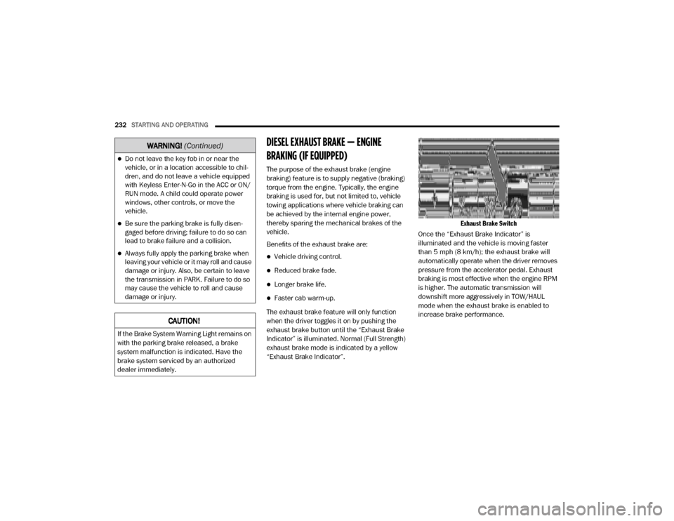
The exhaust brake feature will only function
when the driver toggles it on by pushing the
exhaust brake button until the “Exhaust Brake
Indicator” is illuminated. Normal (Full Strength)
exhaust brake mode is indicated by a yellow
“Exhaust Brake Indicator”.
Exhaust Brake Switch
Once the “Exhaust Brake Indicator” is
illuminated and the vehicle is moving faster
than 5 mph (8 km/h); the exhaust brake will
automatically operate when the driver removes
pressure from the accelerator pedal. Exhaust
braking is most effective when the engine RPM
is higher. The automatic transmission will
downshift more aggressively in TOW/HAUL
mode when the exhaust brake is enabled to
increase brake performance.
Do not leave the key fob in or near the
vehicle, or in a location accessible to chil-
dren, and do not leave a vehicle equipped
with Keyless Enter-N-Go in the ACC or ON/
RUN mode. A child could operate power
windows, other controls, or move the
vehicle.
Be sure the parking brake is fully disen -
gaged before driving; failure to do so can
lead to brake failure and a collision.
Always fully apply the parking brake when
leaving your vehicle or it may roll and cause
damage or injury. Also, be certain to leave
the transmission in PARK. Failure to do so
may cause the vehicle to roll and cause
damage or injury.
CAUTION!
If the Brake System Warning Light remains on
with the parking brake released, a brake
system malfunction is indicated. Have the
brake system serviced by an authorized
dealer immediately.
WARNING! (Continued)
20_DJD2_OM_EN_USC_t.book Page 232
Page 240 of 568

238STARTING AND OPERATING
conditions, using a lower gear range will
improve performance and extend transmission
life by reducing excessive shifting and heat
buildup.
During extremely cold temperatures (-22°F
[-30°C] or below), transmission operation may
be modified depending on engine and
transmission temperature as well as vehicle
speed. Normal operation will resume once the
transmission temperature has risen to a
suitable level.
Transmission Limp Home Mode
Transmission function is monitored
electronically for abnormal conditions. If a
condition is detected that could result in
transmission damage, Transmission Limp
Home Mode is activated. In this mode, the
transmission may operate only in certain gears,
or may not shift at all. Vehicle performance may
be severely degraded and the engine may stall.
In some situations, the transmission may not
re-engage if the engine is turned off and
restarted. The Malfunction Indicator Light (MIL)
may be illuminated. A message in the
instrument cluster will inform the driver of the
more serious conditions, and indicate what
actions may be necessary. In the event of a momentary problem, the
transmission can be reset to regain all forward
gears by performing the following steps:
NOTE:
In cases where the instrument cluster message
indicates the transmission may not re-engage
after engine shutdown, perform this procedure
only in a desired location (preferably, at an
authorized dealer).
1. Stop the vehicle.
2. Shift the transmission into PARK, if
possible. If not, shift the transmission to
NEUTRAL.
3. Push and hold the ignition switch until the engine turns off.
4. Wait approximately 30 seconds.
5. Restart the engine.
6. Shift into the desired gear range. If the problem is no longer detected, the
transmission will return to normal
operation. NOTE:
Even if the transmission can be reset, we
recommend that you visit an authorized dealer
at your earliest possible convenience. An autho
-
rized dealer has diagnostic equipment to
assess the condition of your transmission.
If the transmission cannot be reset, authorized
dealer service is required.
Electronic Range Select (ERS) Operation
The Electronic Range Select (ERS) shift control
allows the driver to limit the highest available
gear when the transmission is in DRIVE. For
example, if you set the transmission gear limit
to 4 (FOURTH gear), the transmission will not
shift above FOURTH gear (except to prevent
engine overspeed), but will shift through the
lower gears normally.
You can switch between DRIVE and ERS mode
at any vehicle speed. When the transmission
gear selector is in DRIVE, the transmission will
operate automatically, shifting between all
available gears. Tapping the GEAR – switch (on
the steering wheel) will activate ERS mode,
display the current gear in the instrument
cluster, and set that gear as the top available
20_DJD2_OM_EN_USC_t.book Page 238
Page 245 of 568
STARTING AND OPERATING243
During cold temperatures, transmission
operation may be modified depending on
engine and transmission temperature as well
as vehicle speed. This feature improves warm
up time of the engine and transmission to
achieve maximum efficiency. Engagement of
the torque converter clutch is inhibited until the
transmission fluid is warm refer to the “Note”
under “Torque Converter Clutch” in this section.
On Pickup models with 68RFE transmission, top
overdrive gear is also inhibited until the
transmission fluid is warm, and during
extremely cold temperatures (-16°F [-27°C] or
below), operation may briefly be limited to first
and direct gears only. On trucks with AISIN
(AS69RC) transmission, fifth and sixth gears
may be inhibited briefly on cold starts below
41°F (5°C), and during very cold temperatures
(-4°F [-20°C] or below), operation may briefly
be limited to third gear only. During this
condition, the ability of the vehicle to accelerate
under heavily loaded conditions may be
reduced. In all cases, normal operation will
resume once the transmission temperature has
risen to a suitable level.Transmission Limp Home Mode
Transmission function is monitored electronically
for abnormal conditions. If a condition is
detected that could result in transmission
damage, Transmission Limp Home Mode is
activated. In this mode, the transmission remains
in fourth gear (for 68RFE transmission) or third
gear (for AISIN (AS69RC) transmission)
regardless of which forward gear is selected. If an
AISIN (AS69RC)-equipped truck enters Limp
Home Mode at highway speeds, it will initially
engage fifth gear, until the vehicle slows to a
speed where third gear can be engaged. PARK,
REVERSE, and NEUTRAL will continue to operate.
The Malfunction Indicator Light (MIL) may be
illuminated. Limp Home Mode allows the vehicle
to be driven to an authorized dealer for service
without damaging the transmission.
In the event of a momentary problem, the
transmission can be reset to regain all forward
gears by performing the following steps:
1. Stop the vehicle.
2. Shift the transmission into PARK.
3. Turn the ignition off.
4. Wait approximately 10 seconds. 5. Restart the engine.
6. Shift into the desired gear range. If the
problem is no longer detected, the
transmission will return to normal
operation.
NOTE:
Even if the transmission can be reset, we
recommend that you visit an authorized dealer
at your earliest possible convenience. An autho -
rized dealer has diagnostic equipment to
assess the condition of your transmission.
If the transmission cannot be reset, authorized
dealer service is required.
Electronic Range Select (ERS) Operation
The Electronic Range Select (ERS) shift control
allows the driver to limit the highest available
gear when the transmission is in DRIVE. For
example, if you set the transmission gear limit
to 4 (FOURTH gear), the transmission will not
shift above FOURTH gear, but will shift through
the lower gears normally.
You can switch between DRIVE and ERS mode
at any vehicle speed. When the gear selector is
in the DRIVE position, the transmission will
operate automatically, shifting between all
5
20_DJD2_OM_EN_USC_t.book Page 243
Page 250 of 568
248STARTING AND OPERATING
NOTE:
The transfer case NEUTRAL button is located in
the center of the 4WD Control Switch and is
pushed by using a ballpoint pen or similar
object. The transfer case NEUTRAL position is to
be used for recreational towing only. Refer to
“Recreational Towing” in “Starting And Oper -
ating” for further information.
Transfer Case Position Indicator Lights
The Transfer Case Position Indicator Lights
(4WD HIGH and 4WD LOW) are located in the
instrument cluster and indicate the current and
desired transfer case selection. When you
select a different transfer case position, the
indicator lights will do the following:
If All Of The Following Shift Conditions Are Met:
1. The current position indicator light will turn off.
2. The selected position indicator light will flash until the transfer case completes the
shift.
3. When the shift is complete, the indicator light for the selected position will stop
flashing and remain on. If One Or More Of The Following Shift Conditions
Are Not Met:
1. The indicator light for the current position
will remain on.
2. The newly selected position indicator light will continue to flash.
3. The transfer case will not shift.
NOTE:
Before retrying a selection, make certain that all
the necessary requirements for selecting a new
transfer case position have been met. To retry the
selection, push the current position, wait five
seconds, and retry selection. To find the shift
requirements, refer to the “Shifting Procedure”
for your transfer case, located in this section.
The “SVC 4WD Warning Light” monitors the
electronic shift four-wheel drive system. If this
light remains on after engine start up or
illuminates during driving, it means that the
four-wheel drive system is not functioning
properly and that service is required.
NOTE:
Do not attempt to make a shift while only the
front or rear wheels are spinning. This could
cause damage to driveline components. When operating your vehicle in 4WD LOW, the
engine speed is approximately three times that
of the 2WD or 4WD HIGH positions at a given
road speed. Take care not to overspeed the
engine and do not exceed 25 mph (40 km/h).
Proper operation of four-wheel drive vehicles
depends on tires of equal size, type and
circumference on each wheel. Any difference in
tire size can cause damage to the drivetrain.
Because four-wheel drive provides improved
traction, there is a tendency to exceed safe
turning and stopping speeds. Do not go faster
than road conditions permit.
Shifting Procedure
NOTE:
If any of the requirements to select a new
transfer case position have not been met, the
transfer case will not shift. The position indi
-
cator light for the previous position will
remain on and the newly selected position
indicator light will continue to flash until all
the requirements for the selected position
have been met.
If all the requirements to select a new
transfer case position have been met, the
20_DJD2_OM_EN_USC_t.book Page 248
Page 253 of 568
STARTING AND OPERATING251
When additional traction is required, the
transfer case 4WD HIGH and 4WD LOW
positions can be used to maximize torque to the
front driveshaft, forcing the front and rear
wheels to rotate at the same speed. This is
accomplished by rotating the 4WD Control
Switch to the desired position.
Refer to “Shifting Procedure” in this section for
specific shifting instructions.
The 4WD HIGH and 4WD LOW positions are
designed for loose, slippery road surfaces only.
Driving in the 4WD HIGH and 4WD LOW
positions on dry hard surfaced roads may cause
increased tire wear and damage to the driveline
components.
NOTE:
The transfer case NEUTRAL button is located on
the lower left hand corner of the 4WD Control
Switch. The transfer case NEUTRAL position is
to be used for recreational towing only. Refer to
“Recreational Towing” in “Starting And Oper -
ating” for further information. Transfer Case Position Indicator Lights
The Transfer Case Position Indicator Lights
(4WD and 4LOW) are located in the instrument
cluster and indicate the current and desired
transfer case selection. When you select a
different transfer case position, the indicator
lights will do the following:
If All Of The Following Shift Conditions Are Met:
1. The current position indicator light will turn OFF.
2. The selected position indicator light will flash until the transfer case completes the
shift.
3. When the shift is complete, the indicator light for the selected position will stop
flashing and remain ON.
If One Or More Of The Following Shift Conditions
Are Not Met:
1. The indicator light for the current position will remain ON.
2. The newly selected position indicator light will continue to flash.
3. The transfer case will not shift. NOTE:
Before retrying a selection, make certain that all
the necessary requirements for selecting a new
transfer case position have been met. To retry
the selection, turn the control switch back to the
current position, wait five seconds, and retry
selection. To find the shift requirements, refer
to the "Shifting Procedure" for your transfer
case, located in this section.
The “SVC 4WD Warning Light” monitors the
electronic shift four-wheel drive system. If this
light remains on after engine start up or
illuminates during driving, it means that the
four-wheel drive system is not functioning
properly and that service is required.
NOTE:
Do not attempt to make a shift while only the
front or rear wheels are spinning, as this can
cause damage to driveline components.
When operating your vehicle in 4WD LOW, the
engine speed is approximately three times that
of the 2WD or 4WD HIGH positions at a given
road speed. Take care not to overspeed the
engine and do not exceed 25 mph (40 km/h).
5
20_DJD2_OM_EN_USC_t.book Page 251