warning light Ram 3500 2020 User Guide
[x] Cancel search | Manufacturer: RAM, Model Year: 2020, Model line: 3500, Model: Ram 3500 2020Pages: 568
Page 74 of 568

72GETTING TO KNOW YOUR VEHICLE
buffeting occurs with the rear windows open,
open the front and rear windows together to
minimize the buffeting. If the buffeting occurs
with the sunroof open, adjust the sunroof
opening to minimize the buffeting or open any
window.
POWER SUNROOF — IF EQUIPPED
SINGLE PANE POWER SUNROOF — IF
E
QUIPPED
The power sunroof switches are located on the
overhead console between the courtesy/
reading lights.
Power Sunroof Switches
Opening Sunroof
Express
Push the switch rearward and release it within
one-half second. The sunroof and sunshade will
open automatically and stop when the full open
position is reached. This is called “Express
Open.” During Express Open operation, any
other actuation of the sunroof switch will stop
the sunroof.
Manual Mode
To open the sunroof, push and hold the switch
rearward. The sunroof will move rearward and
automatically stop at full open position. Any
release of the switch will stop the movement.
The sunroof and sunshade will remain in a
partially opened condition until the sunroof
switch is pushed again.
Closing Sunroof
Express
Push the switch forward and release it within
one-half second and the sunroof will close
automatically from any position. The sunroof
will close fully and stop automatically. This is
1 — Opening/Closing Sunroof
2 — Venting Sunroof
WARNING!
Never leave children unattended in a
vehicle, or with access to an unlocked
vehicle. Never leave the key fob in or near
the vehicle, or in a location accessible to
children. Do not leave the ignition of a
vehicle equipped with Keyless Enter-N-Go
in the ACC or ON/RUN mode. Occupants,
particularly unattended children, can
become entrapped by the power sunroof
while operating the power sunroof switch.
Such entrapment may result in serious
injury or death.
In a collision, there is a greater risk of being
thrown from a vehicle with an open sunroof.
You could also be seriously injured or killed.
Always fasten your seat belt properly and
make sure all passengers are also properly
secured.
Do not allow small children to operate the
sunroof. Never allow your fingers, other
body parts, or any object, to project through
the sunroof opening. Injury may result.
20_DJD2_OM_EN_USC_t.book Page 72
Page 78 of 568

76GETTING TO KNOW YOUR VEHICLE
(Continued)
To stow the bed step back under the tailgate,
push the bed step forward with your foot until
the bed step is retracted by the spring load.
GARAGE DOOR OPENER — IF EQUIPPED
HomeLink® replaces up to three hand-held
transmitters that operate devices such as
garage door openers, motorized gates, lighting
or home security systems. The HomeLink® unit
is powered by your vehicle’s 12 Volt battery.
The HomeLink® buttons that are located on the
sun visor designate the three different
HomeLink® channels.
HomeLink® Buttons
NOTE:
HomeLink® is disabled when the Vehicle Secu -
rity Alarm is active. NOTE:
Only use this transceiver with a garage door
opener that has a “stop and reverse” feature as
required by federal safety standards. This includes
most garage door opener models manufactured
after 1982. Do not use a garage door opener
without these safety features. Call toll-free
1-800-355-3515 or, on the Internet at
Home-
Link.com
for safety information or assistance.
BEFORE YOU BEGIN PROGRAMMING
H
OMELINK®
Be sure that your vehicle is parked outside of
the garage before you begin programming.
For more efficient programming and accurate
transmission of the Radio Frequency (RF) signal
it is recommended that a new battery be placed
in the hand-held transmitter of the device that is
being programmed to the HomeLink® system.
WARNING!
Do not attempt to stow the bed step with your
hands. The low clearance space between the
bed step and the rear bumper as the bed step
returns to the stowed position could result in
injury to your hands or fingers.
WARNING!
Your motorized door or gate will open and
close while you are programming the
universal transceiver. Do not program the
transceiver if people, pets or other objects
are in the path of the door or gate. Only use
this transceiver with a garage door opener
that has a “stop and reverse” feature as
required by Federal safety standards. This
includes most garage door opener models
manufactured after 1982. Do not use a
garage door opener without these safety
features.
Vehicle exhaust contains carbon monoxide,
a dangerous gas. Do not run your vehicle in
the garage while programming the trans -
ceiver. Exhaust gas can cause serious
injury or death.
WARNING! (Continued)
20_DJD2_OM_EN_USC_t.book Page 76
Page 89 of 568

GETTING TO KNOW YOUR VEHICLE87
(Continued)
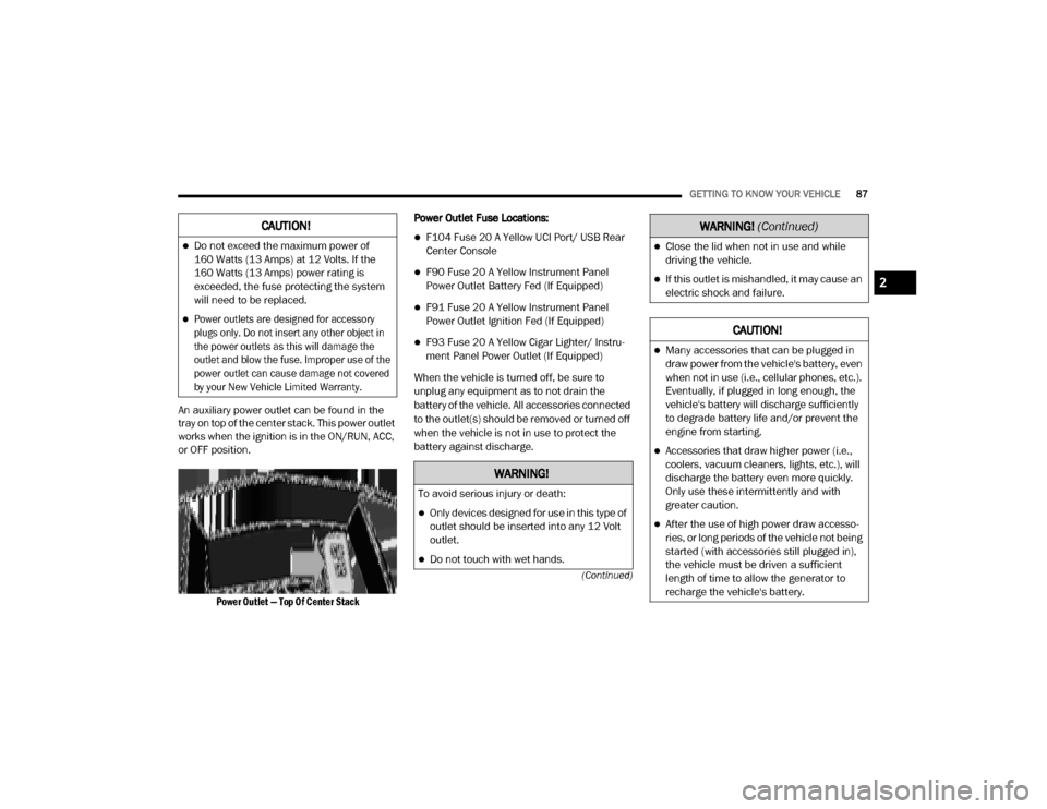
An auxiliary power outlet can be found in the
tray on top of the center stack. This power outlet
works when the ignition is in the ON/RUN, ACC,
or OFF position.
Power Outlet — Top Of Center Stack
Power Outlet Fuse Locations:
F104 Fuse 20 A Yellow UCI Port/ USB Rear
Center Console
F90 Fuse 20 A Yellow Instrument Panel
Power Outlet Battery Fed (If Equipped)
F91 Fuse 20 A Yellow Instrument Panel
Power Outlet Ignition Fed (If Equipped)
F93 Fuse 20 A Yellow Cigar Lighter/ Instru
-
ment Panel Power Outlet (If Equipped)
When the vehicle is turned off, be sure to
unplug any equipment as to not drain the
battery of the vehicle. All accessories connected
to the outlet(s) should be removed or turned off
when the vehicle is not in use to protect the
battery against discharge.
CAUTION!
Do not exceed the maximum power of
160 Watts (13 Amps) at 12 Volts. If the
160 Watts (13 Amps) power rating is
exceeded, the fuse protecting the system
will need to be replaced.
Power outlets are designed for accessory
plugs only. Do not insert any other object in
the power outlets as this will damage the
outlet and blow the fuse. Improper use of the
power outlet can cause damage not covered
by your New Vehicle Limited Warranty.
WARNING!
To avoid serious injury or death:
Only devices designed for use in this type of
outlet should be inserted into any 12 Volt
outlet.
Do not touch with wet hands.
Close the lid when not in use and while
driving the vehicle.
If this outlet is mishandled, it may cause an
electric shock and failure.
CAUTION!
Many accessories that can be plugged in
draw power from the vehicle's battery, even
when not in use (i.e., cellular phones, etc.).
Eventually, if plugged in long enough, the
vehicle's battery will discharge sufficiently
to degrade battery life and/or prevent the
engine from starting.
Accessories that draw higher power (i.e.,
coolers, vacuum cleaners, lights, etc.), will
discharge the battery even more quickly.
Only use these intermittently and with
greater caution.
After the use of high power draw accesso -
ries, or long periods of the vehicle not being
started (with accessories still plugged in),
the vehicle must be driven a sufficient
length of time to allow the generator to
recharge the vehicle's battery.
WARNING! (Continued)
2
20_DJD2_OM_EN_USC_t.book Page 87
Page 91 of 568

GETTING TO KNOW YOUR VEHICLE89
If equipped, there may be a 115 Volt (400 Watts
maximum) inverter located to the right of the
center stack, just below the climate controls.
This inverter can power cellular phones,
electronics and other low power devices
requiring power up to 400 Watts. Certain
high-end video game consoles exceed this
power limit, as will most power tools.
Center Stack Power Inverter
To turn on the power outlet, simply plug in the
device. The outlet turns off when the device is
unplugged.
NOTE:
The Power Inverter only turns on if the igni -
tion is in the ACC or ON/RUN mode.
Due to built-in overload protection, the power
inverter shuts down if the power rating is
exceeded.
WIRELESS CHARGING PAD — IF
E
QUIPPED
Wireless Charging Pad Your vehicle may be equipped with a 15W 3A Qi
wireless charging pad located inside of the center
console. This charging pad is designed to
wirelessly charge your Qi enabled mobile phone.
Qi is a standard that uses magnetic induction to
transfer power to your mobile device.
Your mobile phone must be designed for Qi
wireless charging. If the phone is not equipped
with Qi wireless charging functionality, an
aftermarket sleeve or a specialized back plate
can be purchased from your mobile phone
provider or a local electronics retailer. Please
see your phone’s owner’s manual for further
information.
The wireless charging pad is equipped with an
anti-slip mat, an adjustable cradle to hold your
mobile phone in place and an LED indicator light.
WARNING!
To avoid serious injury or death:
Do not insert any objects into the receptacles.
Do not touch with wet hands.
Close the lid when not in use.
If this outlet is mishandled, it may cause an
electric shock and failure.
CAUTION!
The key fob should not be placed on the
charging pad or within 15 cm (150 mm) of it.
Doing so can cause excessive heat buildup
and damage to the fob. Placing the fob in
close proximity of the charging pad blocks the
fob from being detected by the vehicle and
prevents the vehicle from starting.
2
20_DJD2_OM_EN_USC_t.book Page 89
Page 100 of 568

98GETTING TO KNOW YOUR VEHICLE
SLIDE-IN CAMPERS
CAMPER APPLICATIONS
Certain truck models are not recommended for
slide-in campers. To determine if your vehicle is
excluded, please refer to the “Consumer
Information Truck-Camper Loading” document
at www.ramtrucks.com. For safety reasons,
follow all instructions in this important
document.
NOTE:
When a cap or pickup camper is installed on a
vehicle, an alternate Center High-Mounted Stop
Light (CHMSL) must be provided.
EASY-OFF TAILGATE
To simplify mounting of a camper unit with an
overhang, the tailgate can be removed.
NOTE:
The electric connector at the bottom of the tail -
gate must be disconnected prior to removing
the tailgate.
DISCONNECTING THE REAR CAMERA
A
ND REMOTE KEYLESS ENTRY
1. Open the tailgate to access the rear
camera or Remote Keyless Entry
connector bracket located on the rear sill.
Connector Bracket
2. Remove the connector bracket from the sill
by pushing inward in the locking tab.
Locking Tab
3. Disconnect the chassis wiring harness, ensuring the connector bracket does not
fall into the sill.
4. Connect the chassis plug and bracket (provided in the glove compartment) to the
chassis wiring harness and insert the
bracket back into the sill.
5. Connect the tailgate plug (provided in the glove compartment) to the tailgate wiring
harness to ensure that the terminals do not
corrode.WARNING!
To avoid inhaling carbon monoxide, which is
deadly, the exhaust system on vehicles
equipped with “Cap or Slide-In Campers”
should extend beyond the overhanging
camper compartment and be free of leaks.
20_DJD2_OM_EN_USC_t.book Page 98
Page 112 of 568

110GETTING TO KNOW YOUR INSTRUMENT PANEL
BASE INSTRUMENT CLUSTER — DIESEL ENGINE
Base Instrument Cluster — Diesel Engine
BASE INSTRUMENT CLUSTER
D
ESCRIPTIONS — DIESEL ENGINE
1. Tachometer
Indicates the engine speed in revolutions
per minute (RPM x 1000). 2. Engine Coolant Temperature
This gauge shows the engine coolant
temperature. The gauge pointer will likely
show higher temperatures when driving
in hot weather, up mountain grades, or in
heavy stop and go traffic. If the red Warning Light turns on while driving,
safely bring the vehicle to a stop, and
turn off the engine. DO NOT operate the
vehicle until the cause is corrected.
20_DJD2_OM_EN_USC_t.book Page 110
Page 113 of 568

GETTING TO KNOW YOUR INSTRUMENT PANEL111
3. Instrument Cluster Display
When the appropriate conditions exist,
this display shows the instrument cluster
display messages. Refer to “Instrument
Cluster Display” in “Getting To Know Your
Instrument Panel” for further informa-
tion. 4. Oil Pressure Gauge
The pointer should always indicate some
oil pressure when the engine is running.
A continuous high or low reading under
normal driving conditions may indicate a
lubrication system malfunction. Imme
-
diate service should be obtained from an
authorized dealer.
5. Speedometer
Indicates vehicle speed.
6. Fuel Gauge
The pointer shows the level of fuel in the
fuel tank when the ignition switch is in
the ON/RUN position.
The fuel pump symbol points
to the side of the vehicle where
the fuel filler door is located.
Refer to “Refueling The Vehicle — Gas
Engine” in “Starting And Operating” for
further information.
7. Diesel Exhaust Fluid (DEF) Gauge
The DEF Gauge displays the actual level
of Diesel Exhaust Fluid in the DEF tank.
Diesel Exhaust Fluid (DEF) is required to maintain normal vehicle operation and
emissions compliance. If something is
wrong with the gauge, a DEF Warning
Message or Malfunction Indicator Light
(MIL) will be displayed. More information
is available in the instrument cluster
display section under the heading of
Diesel Exhaust Fluid (DEF) Warning
Messages.
NOTE:
The gauge may take up to five seconds to
update after adding a gallon or more of
Diesel Exhaust Fluid (DEF) to the DEF tank. If
you have a fault related to the DEF system,
the gauge may not update to the new level.
See an authorized dealer for service.
The DEF gauge may also not immediately
update after a refill if the temperature of the
DEF fluid is below 39°F (4°C). The DEF tank
heater will warm up the DEF fluid and allow
the gauge to update after a period of run
time. Under very cold conditions, it is possible
that the gauge may not reflect the new fill
level for several drives.
WARNING!
A hot engine cooling system is dangerous.
You or others could be badly burned by steam
or boiling coolant. You may want to call an
authorized dealer for service if your vehicle
overheats.
CAUTION!
Driving with a hot engine cooling system
could damage your vehicle. If the
temperature gauge reads greater “H,” pull
over and stop the vehicle. Idle the vehicle
with the air conditioner turned off until the
pointer drops back into the normal range. If
the pointer remains on the “h,” turn the
engine off immediately and call an authorized
dealer for service.
3
20_DJD2_OM_EN_USC_t.book Page 111
Page 115 of 568

GETTING TO KNOW YOUR INSTRUMENT PANEL113
The fuel pump symbol points
to the side of the vehicle where
the fuel filler door is located.
Refer to “Refueling The Vehicle — Gas
Engine” in “Starting And Operating” for
further information.
5. Diesel Exhaust Fluid (DEF) Gauge
The DEF Gauge displays the actual level
of Diesel Exhaust Fluid in the DEF tank.
Diesel Exhaust Fluid (DEF) is required to
maintain normal vehicle operation and
emissions compliance. If something is
wrong with the gauge, a DEF Warning
Message or Malfunction Indicator Light
(MIL) will be displayed. More information
is available in the instrument cluster
display section under the heading of
Diesel Exhaust Fluid (DEF) Warning
Messages. NOTE:
The DEF tank on these vehicles is designed
with a large amount of full reserve. So the level
sensor will indicate a full reading even before
the tank is completely full. To put it another
way, there’s additional storage capacity in the
tank above the Full mark that’s not repre
-
sented in the gauge. You may not see any
movement in the reading – even after driving
up to 200 miles (322 kilometers) in some
cases.
The gauge may take up to five seconds to
update after adding a gallon or more of
Diesel Exhaust Fluid (DEF) to the DEF tank. If
you have a fault related to the DEF system,
the gauge may not update to the new level.
See an authorized dealer for service.
The DEF gauge may also not immediately
update after a refill if the temperature of the
DEF fluid is below 39°F (4°C). The DEF tank
heater will warm up the DEF fluid and allow
the gauge to update after a period of run
time. Under very cold conditions, it is possible
that the gauge may not reflect the new fill
level for several drives.
INSTRUMENT CLUSTER DISPLAY
Your vehicle will be equipped with an
instrument cluster display, which offers useful
information to the driver. With the ignition in the
OFF mode, opening/closing of a door will
activate the display for viewing, and display the
total miles, or kilometers, in the odometer. Your
instrument cluster display is designed to display
important information about your vehicle’s
systems and features. Using a driver interactive
display located on the instrument panel, your
instrument cluster display can show you how
systems are working and give you warnings
when they are not. The steering wheel mounted
controls allow you to scroll through the main
menus and submenus. You can access the
specific information you want and make
selections and adjustments.
3
20_DJD2_OM_EN_USC_t.book Page 113
Page 119 of 568

GETTING TO KNOW YOUR INSTRUMENT PANEL117
System Off
ACC Proximity Warning
ACC Unavailable Warning
For further information, refer to “Adaptive
Cruise Control (ACC) — If Equipped” in “Starting
And Operating.”
LaneSense — If Equipped
The instrument cluster display displays the
current LaneSense system settings. The
information displayed depends on LaneSense
system status and the conditions that need to
be met. For further information, refer to
“LaneSense — If Equipped” in “Starting And
Operating.”
Fuel Economy
Push and release the up or down arrow button
until the Fuel Economy menu item is highlighted
in the instrument cluster display. Push and Hold
the right arrow button to reset Average Fuel
Economy.
Current Fuel Economy Gauge
Average Fuel Economy Value
Range To Empty
Trip A/Trip B
Push and release the up or down arrow button
until the Trip menu item is highlighted in the
instrument cluster display. Push and release
the right arrow button to enter the submenus of
Trip A and Trip B. The Trip A or Trip B information
will display the following:
Distance
Average Fuel Economy
Elapsed Time
Push and hold right arrow button to reset all
information.
Trailer Tow — If Equipped
Push and release the up or down arrow button
until the Trailer Tow menu item is highlighted in
the instrument cluster display. Push and
release the right arrow button and the next
screen will display the following trailer trip
information:
Trip Distance (trailer specific): Push and hold
the right arrow button to reset the distance.
Trailer Brake
Output
Type
Gain
Trailer Tire Pressure — If Equipped
Audio
Push and release the up or down arrow button
until the Audio Menu icon/title is highlighted in
the instrument cluster display. This menu will
display the audio source information, including
the Song name, Artist name, and audio source
with an accompanying graphic.
Phone Call Status
When a call is incoming, a Phone Call Status
pop-up will display on the screen. The pop-up
will remain until the phone is answered or
ignored.
NOTE:
The call status will temporarily replace the
previous media source information displayed
on the screen. When the pop-up is no longer
displayed, the display will return to the last used
screen.
3
20_DJD2_OM_EN_USC_t.book Page 117
Page 120 of 568

118GETTING TO KNOW YOUR INSTRUMENT PANEL
Stored Messages
Push and release the up or down arrow button
until the Messages Menu item is highlighted.
This feature shows the number of stored
warning messages. Push and release the right
or left arrow buttons to cycle through stored
messages.
Screen Setup Menu Item
Push and release the up or down arrow button
until the Screen Setup menu item is highlighted
in the instrument cluster display. Push and
release the right arrow button to enter the
Screen Setup submenu. The Screen Setup
feature allows you to change what information
is displayed in the instrument cluster as well as
the location that information is displayed.
Current Gear — If Equipped
Off (Default Setting)
On
Odometer
Unit Without Decimal (Default Setting)
Unit With Decimal Favorite Menu
Speedometer
Vehicle Info
Driver Assist (Show/Hide) — If Equipped
Fuel Economy (Show/Hide)
Trip Info (Show/Hide)
Trailer Tow (Show/Hide) — If Equipped
Audio (Show/Hide)
Messages
Screen Setup
Commercial Settings — If Equipped
NOTE:
Menus with (Show/Hide) can push the Right
arrow button to choose whether to show or hide
this menu in the instrument cluster display.
Upper Left
None
Compass (Default Setting) — If Equipped
Outside Temp — If Equipped
Time
Range To Empty
Average MPG
Current MPG
Trip A Distance
Trip B Distance
Trailer Trip — If Equipped
Trailer Brake — If Equipped
Oil Pressure — If Equipped
Coolant Temperature — If Equipped
Oil Temperature — If Equipped
Battery Voltage — If Equipped
Transmission Temperature — If Equipped
Oil Life — If Equipped
Exhaust Brake — If Equipped
Turbo Boost — If Equipped
Fuel Filter Life — If Equipped
20_DJD2_OM_EN_USC_t.book Page 118