warning light Ram 3500 2020 Owner's Manual
[x] Cancel search | Manufacturer: RAM, Model Year: 2020, Model line: 3500, Model: Ram 3500 2020Pages: 568
Page 6 of 568
4
GARAGE DOOR OPENER — IF EQUIPPED .........76 Before You Begin Programming
HomeLink® .................................................. 76 Canadian/Gate Operator Programming ..... 79
Using HomeLink® ........................................ 79
Security......................................................... 80
Troubleshooting Tips ................................... 80
General Information .................................... 80
INTERNAL EQUIPMENT ........................................81
Storage ......................................................... 81
Cupholders .................................................. 86
Electrical Power Outlets .............................. 86
Power Inverter — If Equipped ..................... 88
Wireless Charging Pad — If Equipped ........ 89
Overhead Sunglass Storage........................ 90
PICKUP BOX .........................................................90
Cargo Camera — If Equipped ...................... 91
RAMBOX — IF EQUIPPED .....................................92
RamBox Integrated Box Side
Storage Bins ................................................. 92 RamBox Safety Warning .............................. 94
Bed Divider — If Equipped ........................... 94
Bed Rail Tie-Down System — If Equipped .. 96
SLIDE-IN CAMPERS .............................................98
Camper Applications ................................... 98 EASY-OFF TAILGATE ........................................... 98
Disconnecting The Rear Camera And
Remote Keyless Entry ................................. 98 Removing The Tailgate ................................ 99
Locking Tailgate ........................................... 99
TRI-FOLD TONNEAU COVER — IF EQUIPPED ..100
Tri-Fold Tonneau Cover Removal.............. 100
Tri-Fold Tonneau Cover Installation.......... 102Tri-Fold Tonneau Cover Cleaning .............. 105
GETTING TO KNOW YOUR
INSTRUMENT PANEL
BASE / MIDLINE INSTRUMENT CLUSTER —
GAS ENGINE........................................................ 106
Base / Midline Instrument Cluster
Descriptions — Gas Engine ....................... 106
PREMIUM INSTRUMENT CLUSTER —
GAS ENGINE........................................................ 108
Premium Instrument Cluster
Descriptions — Gas Engine ....................... 108
BASE INSTRUMENT CLUSTER —
DIESEL ENGINE ................................................. 110
Base Instrument Cluster Descriptions —
Diesel Engine ............................................. 110 PREMIUM INSTRUMENT CLUSTER —
DIESEL ENGINE .................................................. 112
Premium Instrument Cluster
Descriptions — Diesel Engine ................... 112
INSTRUMENT CLUSTER DISPLAY ................... 113
Instrument Cluster Display Controls ........ 114
Oil Life Reset ............................................. 115
Display Menu Items ................................... 116
Diesel Messages And Warnings — 6.7L
Cummins Diesel Engine ............................ 125 Battery Saver On/Battery Saver Mode
Message — Electrical Load Reduction
Actions — If Equipped ............................... 129
WARNING LIGHTS AND MESSAGES ............... 130
Red Warning Lights ................................... 130
Yellow Warning Lights ............................... 133Yellow Indicator Lights .............................. 138
Green Indicator Lights ............................... 140White Indicator Lights ............................... 141Blue Indicator Lights ................................. 142
ONBOARD DIAGNOSTIC SYSTEM — OBD II ... 142
Onboard Diagnostic System
(OBD II) Cybersecurity ............................... 142
EMISSIONS INSPECTION AND MAINTENANCE
PROGRAMS ....................................................... 143
20_DJD2_OM_EN_USC_t.book Page 4
Page 14 of 568
12
HOW TO USE THIS MANUAL
ESSENTIAL INFORMATION
Consult the Table of Contents to determine which section contains the
information you desire.
Since the specification of your vehicle depends on the items of equipment
ordered, certain descriptions and illustrations may differ from your
vehicle's equipment.
The detailed Index at the back of this Owner's Manual contains a
complete listing of all subjects.
SYMBOLS
Some vehicle components have colored labels whose symbols indicate
precautions to be observed when using this component. Refer to
“Warning Lights and Messages” in “Getting To Know Your Instrument
Panel” for further information on the symbols used in your vehicle.
WARNINGS AND CAUTIONS
This Owner’s Manual contains WARNINGS against operating procedures
that could result in a collision, bodily injury and/or death. It also contains
CAUTIONS against procedures that could result in damage to your vehicle.
If you do not read this entire Owner’s Manual, you may miss important
information. Observe all Warnings and Cautions.
VAN CONVERSIONS/CAMPERS
The New Vehicle Limited Warranty does not apply to body modifications or
special equipment installed by van conversion/camper manufacturers/
body builders. US residents refer to the Warranty Information, Section
2.1.C. Canadian residents refer to the “What Is Not Covered” section of
the Warranty Information. Such equipment includes video monitors,
VCRs, heaters, stoves, refrigerators, etc. For warranty coverage and
service on these items, contact the applicable manufacturer.
Operating instructions for the special equipment installed by the
conversion/camper manufacturer should also be supplied with your
vehicle. If these instructions are missing, please contact an authorized
dealer for assistance in obtaining replacement documents from the
applicable manufacturer.
For information on the Body Builder’s Guide refer to www.ramtrucks.com.
This website contains dimensional and technical specifications for your
vehicle. It is intended for Second Stage Manufacturer's technical support.
For service issues, contact an authorized dealer.
VEHICLE MODIFICATIONS/ALTERATIONS
WARNING!
Any modifications or alterations to this vehicle could seriously affect its
roadworthiness and safety and may lead to a collision resulting in
serious injury or death.
20_DJD2_OM_EN_USC_t.book Page 12
Page 21 of 568
GETTING TO KNOW YOUR VEHICLE19
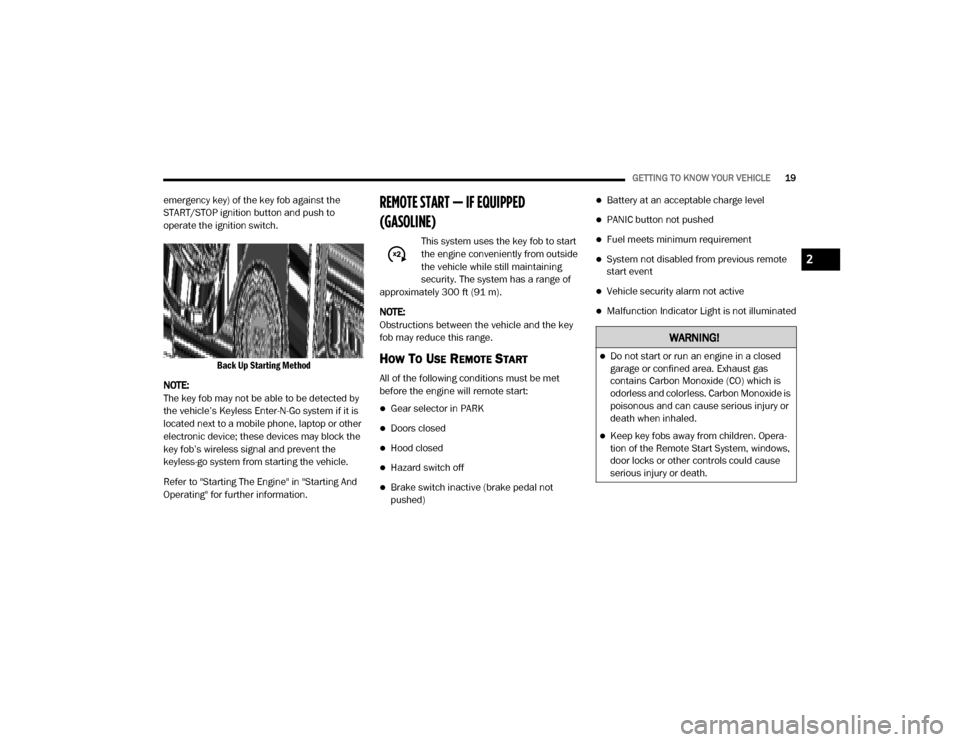
emergency key) of the key fob against the
START/STOP ignition button and push to
operate the ignition switch.
Back Up Starting Method
NOTE:
The key fob may not be able to be detected by
the vehicle’s Keyless Enter-N-Go system if it is
located next to a mobile phone, laptop or other
electronic device; these devices may block the
key fob’s wireless signal and prevent the
keyless-go system from starting the vehicle.
Refer to "Starting The Engine" in "Starting And
Operating" for further information.REMOTE START — IF EQUIPPED
(GASOLINE)
This system uses the key fob to start
the engine conveniently from outside
the vehicle while still maintaining
security. The system has a range of
approximately 300 ft (91 m).
NOTE:
Obstructions between the vehicle and the key
fob may reduce this range.
HOW TO USE REMOTE START
All of the following conditions must be met
before the engine will remote start:
Gear selector in PARK
Doors closed
Hood closed
Hazard switch off
Brake switch inactive (brake pedal not
pushed)
Battery at an acceptable charge level
PANIC button not pushed
Fuel meets minimum requirement
System not disabled from previous remote
start event
Vehicle security alarm not active
Malfunction Indicator Light is not illuminated
WARNING!
Do not start or run an engine in a closed
garage or confined area. Exhaust gas
contains Carbon Monoxide (CO) which is
odorless and colorless. Carbon Monoxide is
poisonous and can cause serious injury or
death when inhaled.
Keep key fobs away from children. Opera -
tion of the Remote Start System, windows,
door locks or other controls could cause
serious injury or death.
2
20_DJD2_OM_EN_USC_t.book Page 19
Page 23 of 568
GETTING TO KNOW YOUR VEHICLE21
NOTE:
The Remote Start Comfort system can be acti -
vated and deactivated through the Uconnect
system under “Auto-On Comfort And Remote
Start”. Refer to “Uconnect Settings” in “Multi -
media” for further information on Remote Start
Comfort System operation.
GENERAL INFORMATION
The following regulatory statement applies to all
Radio Frequency (RF) devices equipped in this
vehicle:
This device complies with Part 15 of the FCC
Rules and with Innovation, Science and
Economic Development Canada license-exempt
RSS standard(s). Operation is subject to the
following two conditions:
1. This device may not cause harmful interference, and
2. This device must accept any interference received, including interference that may
cause undesired operation. Le présent appareil est conforme aux CNR
d`Innovation, Science and Economic
Development applicables aux appareils radio
exempts de licence. L'exploitation est autorisée
aux deux conditions suivantes:
1. l'appareil ne doit pas produire de
brouillage, et
2. l'utilisateur de l'appareil doit accepter tout brouillage radioélectrique subi, même si le
brouillage est susceptible d'en compro -
mettre le fonctionnement.
La operación de este equipo está sujeta a las
siguientes dos condiciones:
1. es posible que este equipo o dispositivo no cause interferencia perjudicial y
2. este equipo o dispositivo debe aceptar cualquier interferencia, incluyendo la que
pueda causar su operación no deseada.
NOTE:
Changes or modifications not expressly
approved by the party responsible for compli -
ance could void the user’s authority to operate
the equipment.
REMOTE START— IF EQUIPPED (DIESEL)
This system uses the key fob to start
the engine conveniently from outside
the vehicle while still maintaining
security. The system has a range of
approximately 300 ft (91 m).
NOTE:
Obstructions between the vehicle and the
key fob may reduce this range.
The Remote Start system will wait for the
Wait To Start indicator light to extinguish
before cranking the engine. This allows time
for the intake heater to preheat the incoming
air, and is normal operation in cold weather.
Refer to “Wait To Start Light”, located in
“Warning Lights And Messages” in “Getting
To Know Your Instrument Panel” for more
information.
2
20_DJD2_OM_EN_USC_t.book Page 21
Page 24 of 568
22GETTING TO KNOW YOUR VEHICLE
HOW TO USE REMOTE START
All of the following conditions must be met
before the engine will remote start:
Transmission in PARK
Doors closed
Hood closed
Hazard switch off
Brake switch inactive (brake pedal not
pushed)
Battery at an acceptable charge level
PANIC button not pushed
Fuel meets minimum requirement
Water In Fuel Indicator Light is not illumi -
nated
Wait To Start Light Indicator Light is not illu -
minated
Malfunction Indicator Light is not illuminated
REMOTE START ABORT MESSAGE
The following messages will display in the
instrument cluster display if the vehicle fails to
remote start or exits remote start prematurely:
Remote Start Aborted — Door Open
Remote Start Aborted — Hood Open
Remote Start Aborted — Fuel Low
Remote Start Aborted — System Fault
The instrument cluster display message is
stored until the ignition is placed in the ON/RUN
position.
TO ENTER REMOTE START MODE
Push and release the Remote Start button on
the key fob twice, within five seconds. The
parking lights will flash and the horn will chirp
twice (if programmed). In cold ambient
temperature conditions, the diesel vehicle may
delay crank up to 30 seconds for the Intake Air
Heater. Once the vehicle has started, the
engine will run for 15 minutes.
NOTE:
Crank may be delayed up to 75 seconds for
intake air heater operation at high altitudes,
and/or extreme cold.
The park lamps will turn on and remain on
during Remote Start mode.
For security, power window and power sunroof
operation (if equipped) are disabled when the
vehicle is in the Remote Start mode.
Additional features, such as windshield
wipers, will also not be available while the
vehicle is in the Remote Start mode.
The engine can be started two consecutive
times (two 15 minute cycles) with the key fob.
However, the ignition switch must be placed in
the ON/RUN position before you can repeat
the start sequence for a third cycle.
WARNING!
Do not start or run an engine in a closed
garage or confined area. Exhaust gas
contains Carbon Monoxide (CO) which is
odorless and colorless. Carbon Monoxide is
poisonous and can cause serious injury or
death when inhaled.
Keep key fobs away from children. Opera -
tion of the Remote Start System, windows,
door locks or other controls could cause
serious injury or death.
20_DJD2_OM_EN_USC_t.book Page 22
Page 28 of 568
26GETTING TO KNOW YOUR VEHICLE
(Continued)
The vehicle security alarm is designed to protect
your vehicle. However, you can create
conditions where the system will give you a false
alarm. If one of the previously described arming
sequences has occurred, the vehicle security
alarm will arm regardless of whether you are in
the vehicle or not. If you remain in the vehicle
and open a door, the alarm will sound. If this
occurs, disarm the vehicle security alarm.
If the vehicle security alarm is armed and the
battery becomes disconnected, the vehicle
security alarm will remain armed when the
battery is reconnected; the exterior lights will
flash, and the horn will sound. If this occurs,
disarm the vehicle security alarm.
REARMING OF THE SYSTEM
If something triggers the alarm, and no action is
taken to disarm it, the vehicle security alarm will
turn the horn off after 29 seconds, 5 seconds
between cycles, up to 8 cycles if the trigger
remains active and then the vehicle security
alarm will rearm itself.
SECURITY SYSTEM MANUAL OVERRIDE
The vehicle security alarm will not arm/disarm if
you lock/unlock the doors using the manual
door lock.
DOORS
MANUAL DOOR LOCKS
Front and rear doors may be locked by moving
the lock knob down. The lock knobs will unlock
when the interior handle is used to open the
doors.
Door Lock Knob
Front doors may be opened with the inside door
handle without lifting the lock knob.
Doors locked before closing will remain locked
when closed.
The emergency key will unlock the driver door
lock on your vehicle.WARNING!
Do not leave children or animals inside
parked vehicles in hot weather. Interior
heat build-up may cause serious injury or
death.
For personal security and safety in the
event of an collision, lock the vehicle doors
as you drive as well as when you park and
leave the vehicle.
Before exiting a vehicle, always shift the
automatic transmission into PARK, apply
the parking brake, turn the vehicle OFF,
remove the key fobs from vehicle, and lock
all doors. and lock your vehicle.
20_DJD2_OM_EN_USC_t.book Page 26
Page 36 of 568

34GETTING TO KNOW YOUR VEHICLE
(Continued)
Manual Front Seat Recline Adjustment
The recline lever is located on the outboard side
of the seat. To recline the seat, lean forward
slightly, lift the lever, lean back to the desired
position and release the lever. To return the
seatback to its normal upright position, lean
forward and lift the lever. Release the lever
once the seat back is in the upright position.
Manual Recline Lever
40-20-40 Front Bench Seat — If Equipped
The seat is divided into three segments. The
outboard seat portions are each 40% of the
total width of the seat. On some models, the
back of the center portion (20%) easily folds
down to provide an armrest/center storage
compartment.
MANUAL REAR SEAT ADJUSTMENT
Reclining Rear Seats — If Equipped
The recliner handle is located on the outside of
the seat cushion. To adjust the seatback, lift
upward on the handle, lean back on the
seatback and when you reach the desired
position, release the handle.
Rear Seat Recliner Handle
WARNING!
Do not stand or lean in front of the seat
while actuating the handle. The seatback
may swing forward and hit you causing
injury.
To avoid injury, place your hand on the seat -
back and actuate the handle, then position
the seatback in the desired position.
WARNING!
Do not pile luggage or cargo higher than the
top of the seatback. This could impair
visibility or become a dangerous projectile in
a sudden stop or collision.
WARNING! (Continued)
WARNING!
Do not ride with the seatback reclined so that
the shoulder belt is no longer resting against
your chest. In a collision you could slide under
the seat belt, which could result in serious
injury or death.
20_DJD2_OM_EN_USC_t.book Page 34
Page 46 of 568

44GETTING TO KNOW YOUR VEHICLE
the tailgate handle. The auto dimming feature is
also disabled to improve rear view viewing.
Automatic Dimming Mirror With Rear View Camera
OUTSIDE MIRRORS
To receive maximum benefit, adjust the outside
mirrors to center on the adjacent lane of traffic
with a slight overlap of the view obtained on the
inside mirror.
NOTE:
If your vehicle is equipped with puddle lamps
under the outside mirrors, they can be turned off through the Uconnect display. For further
information, refer to “Uconnect Settings” in
“Multimedia”.
DRIVER'S OUTSIDE AUTOMATIC
D
IMMING MIRROR — IF EQUIPPED
The driver’s outside mirror will automatically
adjust for glare from vehicles behind you. This
feature is controlled by the inside automatic dimming mirror and will automatically adjust for
headlight glare when the inside mirror adjusts.
POWER MIRRORS — IF EQUIPPED
The controls for the power mirrors are located
on the driver's door trim panel.
Power Mirror Controls
WARNING!
Vehicles and other objects seen in the
passenger side convex mirror will look smaller
and farther away than they really are. Relying
too much on your passenger side convex
mirror could cause you to collide with another
vehicle or other object. Use your inside mirror
when judging the size or distance of a vehicle
seen in the passenger side convex mirror.
Some vehicles will not have a convex
passenger side mirror.
1 — Mirror Direction Control
2 — Right Mirror Selection
3 — Left Mirror Selection
20_DJD2_OM_EN_USC_t.book Page 44
Page 57 of 568
GETTING TO KNOW YOUR VEHICLE55
NOTE:
If your vehicle is equipped with Illuminated
Approach lights under the outside mirrors, they
can also be turned off by pushing the Dome
Defeat button.
WINDSHIELD WIPERS AND WASHERS
WINDSHIELD WIPERS
The wipers and washers are operated by a
switch in the multifunction lever, and can only
be operated with the ignition in the ACC or ON/
RUN position. Turn the end of the lever to select
the desired wiper speed.
Windshield Wiper/Washer Switch
Rotate the end of the lever upward, to the first
detent past the intermittent settings for
low-speed wiper operation. Rotate the end of the lever upward to the second detent past the
intermittent settings for high-speed wiper
operation.
Intermittent Wiper System
The intermittent feature of this system was
designed for use when weather conditions
make a single wiping cycle, with a variable
pause between cycles, desirable. For maximum
delay between cycles, rotate the control knob
upward to the first detent.
The delay interval decreases as you rotate the
knob until it enters the low continual speed
position. The delay can be regulated from a
maximum of about 18 seconds between cycles,
to a cycle every one second. The delay intervals
will double in duration when the vehicle speed
is 10 mph (16 km/h) or less.
Windshield Washers
To use the windshield washer, push the washer
knob, located on the end of the multifunction
lever, inward to the second detent. Washer fluid
will be sprayed and the wiper will operate for
two to three cycles after the washer knob is
released from this position.
If the washer knob is depressed while in the
delay range, the wiper will operate for several
seconds after the washer knob is released. It
will then resume the intermittent interval
previously selected. If the washer knob is
pushed while in the off position, the wiper will
turn on and cycle approximately three times
after the wash knob is released.
To prevent freeze-up of your windshield washer
system in cold weather, select a solution or
mixture that meets or exceeds the temperature
range of your climate. This rating information
can be found on most washer fluid containers.
WARNING!
Sudden loss of visibility through the
windshield could lead to a collision. You might
not see other vehicles or other obstacles. To
avoid sudden icing of the windshield during
freezing weather, warm the windshield with
the defroster before and during windshield
washer use.
2
20_DJD2_OM_EN_USC_t.book Page 55
Page 73 of 568

GETTING TO KNOW YOUR VEHICLE71
during auto closure. If this happens, pull the
switch lightly to the first detent and hold to close
the window manually.
Reset Auto-Up
Should the Auto-Up feature stop working, the
window may need to be reset. To reset Auto-Up:
1. Make sure the door is fully closed.
2. Pull the window switch up to close the
window completely and continue to hold the
switch up for an additional two seconds
after the window is closed.
3. Push the window switch down firmly to the second detent to open the window
completely and continue to hold the switch
down for an additional two seconds after
the window is fully open.
Window Lockout Switch
The window lockout switch on the driver's door
allows you to disable the window control on the
rear passenger doors. To disable the window
controls on the rear passenger doors, push the
window lock switch into the latched or down
position. To enable the window controls, push
the window lock switch again and return the
switch to the released or up position.
Window Lockout Switch
Power Sliding Rear Window — If Equipped
The switch for the power sliding rear window is
located on the overhead console.
Power Sliding Rear Window Switch
Push the rearward portion of the switch to open
the window. Push the forward portion of the
switch to close the window.
Manual Sliding Rear Window — If Equipped
A locking device in the center of the window
helps to prevent entry from the rear of the
vehicle. Squeeze the lock to release the
window.
WIND BUFFETING
Wind buffeting can be described as the
perception of pressure on the ears or a
helicopter-type sound in the ears. Your vehicle
may exhibit wind buffeting with the windows
down, or the sunroof (if equipped) in certain
open or partially open positions. This is a normal
occurrence and can be minimized. If the
WARNING!
There is no anti-pinch protection when the
window is almost closed. Be sure to clear all
objects from the window before closing.2
20_DJD2_OM_EN_USC_t.book Page 71