4WD Ram 3500 2020 Owner's Manual
[x] Cancel search | Manufacturer: RAM, Model Year: 2020, Model line: 3500, Model: Ram 3500 2020Pages: 568
Page 139 of 568
GETTING TO KNOW YOUR INSTRUMENT PANEL137
Anti-Lock Brake System(ABS) Warning
Light
This warning light monitors the
Anti-Lock Brake System (ABS). The
light will turn on when the ignition is
placed in the ON/RUN or ACC/ON/
RUN position and may stay on for as long as
four seconds.
If the ABS light remains on or turns on while
driving, then the Anti-Lock portion of the brake system is not functioning and service is
required as soon as possible. However, the
conventional brake system will continue to
operate normally, assuming the Brake Warning
Light is not also on.
If the ABS light does not turn on when the
ignition is placed in the ON/RUN or ACC/ON/
RUN position, have the brake system inspected
by an authorized dealer.
Rear Axle Locker Fault Indicator Light — If
Equipped
This warning light will illuminate to
indicate when a rear axle locker fault
has been detected.
Refer to “Axle Locker System — Power Wagon
Models Only (If Equipped)” in “Starting And
Operating” for further information.
Service Forward Collision Warning (FCW)
Light — If Equipped
This warning light will illuminate to
indicate a fault in the Forward
Collision Warning System. Contact an
authorized dealer for service.
Refer to "Forward Collision Warning (FCW)" in
"Safety" for further information.
Service 4WD Warning Light — If Equipped
This warning light will illuminate to
signal a fault with the 4WD system. If
the light stays on or comes on during
driving, it means that the 4WD system
is not functioning properly and that service is
required. We recommend you drive to the
nearest service center and have the vehicle
serviced immediately.
Speed Control Fault Warning Light
This warning light will illuminate to
indicate the Speed Control System is
not functioning properly and service is
required. Contact an authorized dealer.
Sway Bar Fault Warning Light
This light will illuminate when there is
a fault in the sway bar disconnect
system.
Refer to “Stabilizer/Sway Bar System — Power
Wagon Only” in “Starting And Operating” for
further information.
CAUTION!
The TPMS has been optimized for the original
equipment tires and wheels. TPMS pressures
and warning have been established for the
tire size equipped on your vehicle.
Undesirable system operation or sensor
damage may result when using replacement
equipment that is not of the same size, type,
and/or style. Aftermarket wheels can cause
sensor damage. Using aftermarket tire
sealants may cause the Tire Pressure
Monitoring System (TPMS) sensor to become
inoperable. After using an aftermarket tire
sealant it is recommended that you take your
vehicle to an authorized dealer to have your
sensor function checked.
3
20_DJD2_OM_EN_USC_t.book Page 137
Page 141 of 568
GETTING TO KNOW YOUR INSTRUMENT PANEL139
Air Suspension Bed Lowering Mode
Indicator Light — If Equipped
This light will illuminate when the Bed
Lowering Mode procedure is
complete.
Refer to “Air Suspension System — If Equipped”
in “Starting And Operating” for further
information.
Air Suspension Ride Height Raising
Indicator Light — If Equipped
This light will blink and alert the driver
that the vehicle is changing to a
higher ride height.
Refer to “Air Suspension System — If Equipped”
in “Starting And Operating” for further
information.
Air Suspension Ride Height Lowering
Indicator Light — If Equipped
This light will blink and alert the driver
that the vehicle is changing to a lower
ride height.
Refer to “Air Suspension System — If Equipped”
in “Starting And Operating” for further
information.
Front And Rear Axle Lock Indicator Light
This light indicates when the front,
rear, or both axles have been locked.
The telltale will display the lock icon
on the front and rear axles to indicate
the current lock status.
Rear Axle Lock Indicator Light
This light indicates when the rear axle
lock has been activated.
Refer to “Four Wheel Drive Operation
— If Equipped” in “Starting And Operating” for
further information.
4WD Lock Indicator Light
This light alerts the driver that the
vehicle is in the four-wheel drive LOCK
mode. The front and rear driveshafts
are mechanically locked together,
forcing the front and rear wheels to rotate at the
same speed.
Refer to “Four-Wheel Drive Operation” in
“Starting And Operating” for further information
on four-wheel drive operation and proper use.
4WD Low Indicator Light — If Equipped
This light alerts the driver that the
vehicle is in the four-wheel drive LOW
mode. The front and rear driveshafts
are mechanically locked together
forcing the front and rear wheels to rotate at the
same speed. Low range provides a greater gear
reduction ratio to provide increased torque at
the wheels.
Refer to “Four-Wheel Drive Operation — If
Equipped” in “Starting And Operating” for
further information on four-wheel drive
operation and proper use.
4WD High Indicator Light — If Equipped
This light alerts the driver that the
vehicle is in the four-wheel drive HIGH
mode. The front and rear driveshafts
are mechanically locked together
forcing the front and rear wheels to rotate at the
same speed.
NEUTRAL Indicator Light — If Equipped
This light alerts the driver that the 4WD
power transfer case is in the NEUTRAL
mode and the front and rear driveshafts
are disengaged from the powertrain.
3
20_DJD2_OM_EN_USC_t.book Page 139
Page 143 of 568
GETTING TO KNOW YOUR INSTRUMENT PANEL141
to provide visual and torque warnings if an
unintentional lane departure occurs.
Refer to “LaneSense — If Equipped” in “Starting
And Operating” for further information.
Front Fog Indicator Light — If Equipped
This indicator light will illuminate
when the front fog lights are on.
Refer to “Exterior Lights” in “Getting
To Know Your Vehicle” for further information.
Turn Signal Indicator Lights
When the left or right turn signal is
activated, the turn signal indicator will
flash independently and the
corresponding exterior turn signal
lamps will flash. Turn signals can be activated
when the multifunction lever is moved down
(left) or up (right).
NOTE:
A continuous chime will sound if the vehicle is
driven more than 1 mile (1.6 km) with either
turn signal on.
Check for an inoperative outside light bulb if
either indicator flashes at a rapid rate.
If equipped with fog lamps, the fog lamp on the
side of the activated turn signal will also illumi -
nate to provide additional light when turning.
Cruise Control Set Indicator Light — If
Equipped
This indicator light will illuminate
when the cruise control is set to the
desired speed. Refer to “Speed
Control” in “Starting And Operating”
for further information.
WHITE INDICATOR LIGHTS
Adaptive Cruise Control (ACC) Ready Light
— If Equipped
This light will illuminate when the vehicle
equipped with Adaptive Cruise Control
(ACC) has been turned on but not set.
Refer to “Adaptive Cruise Control (ACC) — If
Equipped” in “Starting And Operating” for
further information.
Cruise Control Ready Indicator
This indicator light will illuminate
when the cruise control is ready,
but not set. Refer to “Speed Control”
in “Starting And Operating” for
further information.
Hill Descent Control (HDC) Indicator Light
— If Equipped
This indicator shows when the Hill
Descent Control (HDC) feature is
turned on. The lamp will be on solid
when HDC is armed. HDC can only be
armed when the transfer case is in the “4WD
LOW” position and the vehicle speed is less
then 20 mph (32 km/h). If these conditions are
not met while attempting to use the HDC
feature, the HDC indicator light will flash on/off.
LaneSense Indicator Light — If Equipped
When the LaneSense system is ON,
but not armed, the LaneSense
indicator light illuminates solid white.
This occurs when only left, right, or
neither lane line has been detected. If a single
lane line is detected, the system is ready to
provide only visual warnings if an unintentional
lane departure occurs on the detected lane line.
Refer to “LaneSense — If Equipped” in “Starting
And Operating” for further information.
3
20_DJD2_OM_EN_USC_t.book Page 141
Page 218 of 568

216STARTING AND OPERATING
If the driver shifts into PARK while moving, the
vehicle may AutoPark.
AutoPark will engage ONLY when vehicle speed
is 1.2 mph (1.9 km/h) or less.
The message “ Vehicle Speed is Too High to
Shift to P ” will be displayed in the instrument
cluster if vehicle speed is above 1.2 mph
(1.9 km/h).
4WD LOW — If Equipped
AutoPark will be disabled when operating the
vehicle in 4WD LOW.
The message “ AutoPark Disabled ” will be
displayed in the instrument cluster. Additional customer warnings will be given
when all of these conditions are met:
Vehicle is not in PARK
Driver’s door is ajar
Vehicle is in 4WD LOW range
The message “ AutoPark Not Engaged ” will be
displayed in the instrument cluster. A warning
chime will continue until you shift the vehicle
into PARK or the driver’s door is closed.
ALWAYS DO A VISUAL CHECK
that your vehicle
is in PARK by looking for the “P” in the
Instrument Cluster Display and near the shifter.
As an added precaution, always apply the
parking brake when exiting the vehicle.
If Engine Fails To Start
If the engine fails to start after you have
followed the “Normal Starting” procedure, it
may be flooded. Push the accelerator pedal all
the way to the floor and hold it there while the
engine is cranking. This should clear any excess
fuel in case the engine is flooded. The starter motor will engage automatically, run
for 10 seconds, and then disengage. Once this
occurs, release the accelerator pedal and the
brake pedal, wait 10 to 15 seconds, then repeat
the “Normal Starting” procedure.
WARNING!
If vehicle speed is above 1.2 mph (1.9 km/h),
the transmission will default to NEUTRAL until
the vehicle speed drops below 1.2 mph
(1.9 km/h). A vehicle left in the NEUTRAL
position can roll. As an added precaution,
always apply the parking brake when exiting
the vehicle.
WARNING!
Never pour fuel or other flammable liquid
into the throttle body air inlet opening in an
attempt to start the vehicle. This could result
in flash fire causing serious personal injury.
Do not attempt to push or tow your vehicle to
get it started. Vehicles equipped with an
automatic transmission cannot be started
this way. Unburned fuel could enter the cata
-
lytic converter and once the engine has
started, ignite and damage the converter
and vehicle.
If the vehicle has a discharged battery,
booster cables may be used to obtain a
start from a booster battery or the battery in
another vehicle. This type of start can be
dangerous if done improperly. Refer to
“Jump Starting Procedure” in “In Case Of
Emergency” for further information.
20_DJD2_OM_EN_USC_t.book Page 216
Page 248 of 568
246STARTING AND OPERATING
AUXILIARY SWITCHES — IF EQUIPPED
There can be up to six auxiliary switches located
in the lower switch bank of the instrument panel
which can be used to power various electronic
devices and PTO (Power Take Off) – If Equipped.
If Power Take Off is equipped, it will take the
place of the sixth Auxiliary switch. Connections
to the switches are found under the hood in the
connectors attached to the auxiliary Power
Distribution Center.
You have the ability to configure the
functionality of the auxiliary switches via the
instrument cluster display. All switches can now
be configured for setting the switch type
operation to latching or momentary, power
source of either battery or ignition, and ability to
hold last state across key cycles.
NOTE:
Holding last state conditions are met when
switch type is set to latching and power source
is set to ignition.
For further information on using the auxiliary
switches, please refer to the Ram Body Builders
Guide by accessing www.rambodybuilder.com
and choosing the appropriate links.
ACTIVE NOISE CANCELLATION
Your vehicle is equipped with an Active Noise
Cancellation system that cannot be turned off.
This system is designed to address exhaust and
engine noise. The system relies on four
microphones embedded in the headliner, which
monitor exhaust and engine noise, and assists
an onboard frequency generator, which creates
counteracting sound waves in the audio
system’s speakers. This helps keep the vehicle
quiet at idle and during drive. The system is
deactivated when the windows are rolled down.
FOUR-WHEEL DRIVE OPERATION — IF
EQUIPPED
Four-wheel drive trucks are equipped with
either a manually shifted transfer case or an
electronically shifted transfer case. Refer to the
operating instructions for your transfer case,
located in this section for further information.
ELECTRONICALLY SHIFTED TRANSFER
C
ASE (EIGHT SPEED TRANSMISSION) —
I
F EQUIPPED
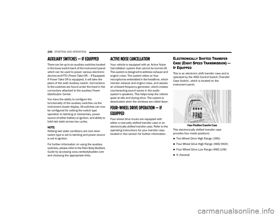
This is an electronic shift transfer case and is
operated by the 4WD Control Switch (Transfer
Case Switch), which is located on the
instrument panel.
Four-Position Transfer Case
This electronically shifted transfer case
provides four mode positions:
Two-Wheel Drive High Range (2WD)
Four-Wheel Drive High Range (4WD HIGH)
Four-Wheel Drive Low Range (4WD LOW)
N (Neutral)
20_DJD2_OM_EN_USC_t.book Page 246
Page 249 of 568
STARTING AND OPERATING247
For additional information on the appropriate
use of each transfer case mode position, see
the information below:
2WD
Two-Wheel Drive High Range — This range is for
normal street and highway driving on dry hard
surfaced roads.
4WD HIGH
Four-Wheel Drive High Range — This range
provides torque to the front driveshaft (engages
four-wheel drive) which allows front and rear
wheels to spin at the same speed. This provides
additional traction for loose, slippery road
surfaces only.
4WD LOW
Four-Wheel Drive Low Range — This range
provides low speed four-wheel drive. It
maximizes torque (increased torque over 4WD
HIGH) to the front driveshaft, allowing front and
rear wheels to rotate at the same speed. This
range provides additional traction and
maximum pulling power for loose, slippery road
surfaces only. Do not exceed 25 mph (40 km/h)
in this range. N (Neutral)
N (Neutral) — This range disengages both the
front and rear driveshafts from the powertrain.
To be used for flat towing behind another
vehicle. Refer to “Recreational Towing” in this
section for further information.
This electronically shifted transfer case is
designed to be driven in the two–wheel drive
position (2WD) for normal street and highway
conditions on dry hard surfaced roads. Driving
the vehicle in 2WD will have greater fuel
economy benefits as the front axle is not
engaged in 2WD.
When additional traction is required, the
transfer case 4WD HIGH and 4WD LOW
positions can be used to maximize torque to the
front driveshaft, forcing the front and rear
wheels to rotate at the same speed. This is
accomplished by pushing the desired position
on the 4WD control switch.
Refer to “Shifting Procedure” in this section for
specific shifting instructions.
The 4WD HIGH and 4WD LOW positions are
designed for loose, slippery road surfaces only.
Driving in the 4WD HIGH and 4WD LOW
positions on dry hard surfaced roads may cause
increased tire wear and damage to the driveline
components.
WARNING!
You or others could be injured or killed if you
leave the vehicle unattended with the
transfer case in the NEUTRAL (N) position
without first fully engaging the parking brake.
The transfer case NEUTRAL (N) position
disengages both the front and rear drive
shaft from the powertrain, and will allow the
vehicle to roll, even if the transmission is in
PARK. The parking brake should always be
applied when the driver is not in the vehicle.
The transmission may not engage PARK if the
vehicle is moving. Always bring the vehicle to
a complete stop before shifting to PARK, and
verify that the transmission gear position indi
-
cator solidly indicates PARK (P) without
blinking. Ensure that the vehicle is completely
stopped, and the PARK position is properly
indicated, before exiting the vehicle.
5
20_DJD2_OM_EN_USC_t.book Page 247
Page 250 of 568
248STARTING AND OPERATING
NOTE:
The transfer case NEUTRAL button is located in
the center of the 4WD Control Switch and is
pushed by using a ballpoint pen or similar
object. The transfer case NEUTRAL position is to
be used for recreational towing only. Refer to
“Recreational Towing” in “Starting And Oper -
ating” for further information.
Transfer Case Position Indicator Lights
The Transfer Case Position Indicator Lights
(4WD HIGH and 4WD LOW) are located in the
instrument cluster and indicate the current and
desired transfer case selection. When you
select a different transfer case position, the
indicator lights will do the following:
If All Of The Following Shift Conditions Are Met:
1. The current position indicator light will turn off.
2. The selected position indicator light will flash until the transfer case completes the
shift.
3. When the shift is complete, the indicator light for the selected position will stop
flashing and remain on. If One Or More Of The Following Shift Conditions
Are Not Met:
1. The indicator light for the current position
will remain on.
2. The newly selected position indicator light will continue to flash.
3. The transfer case will not shift.
NOTE:
Before retrying a selection, make certain that all
the necessary requirements for selecting a new
transfer case position have been met. To retry the
selection, push the current position, wait five
seconds, and retry selection. To find the shift
requirements, refer to the “Shifting Procedure”
for your transfer case, located in this section.
The “SVC 4WD Warning Light” monitors the
electronic shift four-wheel drive system. If this
light remains on after engine start up or
illuminates during driving, it means that the
four-wheel drive system is not functioning
properly and that service is required.
NOTE:
Do not attempt to make a shift while only the
front or rear wheels are spinning. This could
cause damage to driveline components. When operating your vehicle in 4WD LOW, the
engine speed is approximately three times that
of the 2WD or 4WD HIGH positions at a given
road speed. Take care not to overspeed the
engine and do not exceed 25 mph (40 km/h).
Proper operation of four-wheel drive vehicles
depends on tires of equal size, type and
circumference on each wheel. Any difference in
tire size can cause damage to the drivetrain.
Because four-wheel drive provides improved
traction, there is a tendency to exceed safe
turning and stopping speeds. Do not go faster
than road conditions permit.
Shifting Procedure
NOTE:
If any of the requirements to select a new
transfer case position have not been met, the
transfer case will not shift. The position indi
-
cator light for the previous position will
remain on and the newly selected position
indicator light will continue to flash until all
the requirements for the selected position
have been met.
If all the requirements to select a new
transfer case position have been met, the
20_DJD2_OM_EN_USC_t.book Page 248
Page 251 of 568
STARTING AND OPERATING249
current position indicator light will turn off,
the selected position indicator light will flash
until the transfer case completes the shift.
When the shift is complete, the position indi -
cator light for the selected position will stop
flashing and remain on.
2WD To 4WD HIGH
Push the desired position on the 4WD control
switch to shift the transfer case. Shifts between
2WD and 4WD HIGH can be done with the
vehicle stopped or in motion. With the vehicle in
motion, the transfer case will engage/
disengage faster if you momentarily release the
accelerator pedal after turning the control
switch. If the vehicle is stopped, the ignition
switch must be in the ON position with the
engine either running or off. This shift cannot be
completed if the ignition switch is in the ACC
position.
NOTE:
The four-wheel drive system will not allow shifts
between 2WD/4WD HIGH if the front and/or
rear wheels are spinning (no traction). In this
situation, the selected position indicator light
will flash and the original position indicator light will remain on. At this time, reduce speed and
stop spinning the wheels to complete the shift.
2WD Or 4WD HIGH To 4WD LOW
NOTE:
When shifting into or out of 4WD LOW some
gear noise may be heard. This noise is normal
and is not detrimental to the vehicle or occu
-
pants.
Shifting can be performed with the vehicle
rolling 2 to 3 mph (3 to 5 km/h) or completely
stopped. You can use either of the following
procedures:
Preferred Procedure
1. With the engine running, slow the vehicle to 2 to 3 mph (3 to 5 km/h).
2. Shift the transmission into NEUTRAL.
3. While still rolling, push the desired position on the transfer case control switch.
4. After the desired position indicator light is on (not flashing), shift the transmission
back into gear. Alternate Procedure
1. Bring the vehicle to a complete stop.
2. With the ignition switch in the ON position
and the engine running, shift the
transmission into NEUTRAL.
3. Push the desired position on the transfer case control switch.
4. After the desired position indicator light is on (not flashing), shift the transmission
back into gear.
NOTE:
If Steps 1 or 2 of either the Preferred or Alter -
nate Procedure are not satisfied prior to
attempting the shift, then the desired posi -
tion indicator light will flash continuously
while the original position indicator light is
on, until all requirements have been met.
The ignition switch must be in the ON position
for a shift to take place and for the position
indicator lights to be operable. If the ignition
switch is not in the ON position, the shift will
not take place and no position indicator lights
will be on or flashing.
5
20_DJD2_OM_EN_USC_t.book Page 249
Page 252 of 568
250STARTING AND OPERATING
ELECTRONICALLY SHIFTED TRANSFER
C
ASE (SIX SPEED TRANSMISSION) — IF
E
QUIPPED
The electronic shift transfer case is operated by
the 4WD Control Switch (Transfer Case Switch),
which is located on the instrument panel.
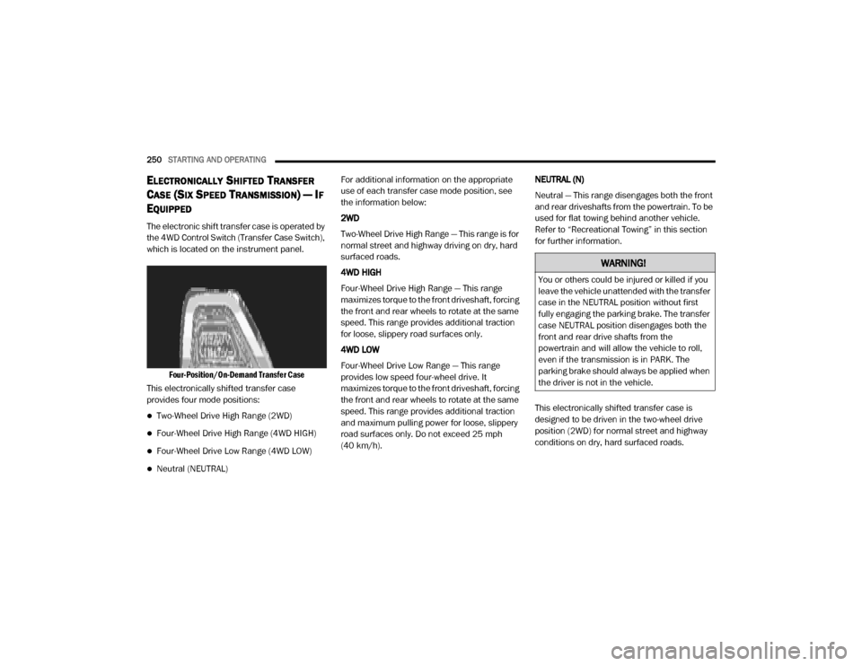
Four-Position/On-Demand Transfer Case
This electronically shifted transfer case
provides four mode positions:
Two-Wheel Drive High Range (2WD)
Four-Wheel Drive High Range (4WD HIGH)
Four-Wheel Drive Low Range (4WD LOW)
Neutral (NEUTRAL) For additional information on the appropriate
use of each transfer case mode position, see
the information below:
2WD
Two-Wheel Drive High Range — This range is for
normal street and highway driving on dry, hard
surfaced roads.
4WD HIGH
Four-Wheel Drive High Range — This range
maximizes torque to the front driveshaft, forcing
the front and rear wheels to rotate at the same
speed. This range provides additional traction
for loose, slippery road surfaces only.
4WD LOW
Four-Wheel Drive Low Range — This range
provides low speed four-wheel drive. It
maximizes torque to the front driveshaft, forcing
the front and rear wheels to rotate at the same
speed. This range provides additional traction
and maximum pulling power for loose, slippery
road surfaces only. Do not exceed 25 mph
(40 km/h).
NEUTRAL (N)
Neutral — This range disengages both the front
and rear driveshafts from the powertrain. To be
used for flat towing behind another vehicle.
Refer to “Recreational Towing” in this section
for further information.
This electronically shifted transfer case is
designed to be driven in the two-wheel drive
position (2WD) for normal street and highway
conditions on dry, hard surfaced roads.
WARNING!
You or others could be injured or killed if you
leave the vehicle unattended with the transfer
case in the NEUTRAL position without first
fully engaging the parking brake. The transfer
case NEUTRAL position disengages both the
front and rear drive shafts from the
powertrain and will allow the vehicle to roll,
even if the transmission is in PARK. The
parking brake should always be applied when
the driver is not in the vehicle.
20_DJD2_OM_EN_USC_t.book Page 250
Page 253 of 568
STARTING AND OPERATING251
When additional traction is required, the
transfer case 4WD HIGH and 4WD LOW
positions can be used to maximize torque to the
front driveshaft, forcing the front and rear
wheels to rotate at the same speed. This is
accomplished by rotating the 4WD Control
Switch to the desired position.
Refer to “Shifting Procedure” in this section for
specific shifting instructions.
The 4WD HIGH and 4WD LOW positions are
designed for loose, slippery road surfaces only.
Driving in the 4WD HIGH and 4WD LOW
positions on dry hard surfaced roads may cause
increased tire wear and damage to the driveline
components.
NOTE:
The transfer case NEUTRAL button is located on
the lower left hand corner of the 4WD Control
Switch. The transfer case NEUTRAL position is
to be used for recreational towing only. Refer to
“Recreational Towing” in “Starting And Oper -
ating” for further information. Transfer Case Position Indicator Lights
The Transfer Case Position Indicator Lights
(4WD and 4LOW) are located in the instrument
cluster and indicate the current and desired
transfer case selection. When you select a
different transfer case position, the indicator
lights will do the following:
If All Of The Following Shift Conditions Are Met:
1. The current position indicator light will turn OFF.
2. The selected position indicator light will flash until the transfer case completes the
shift.
3. When the shift is complete, the indicator light for the selected position will stop
flashing and remain ON.
If One Or More Of The Following Shift Conditions
Are Not Met:
1. The indicator light for the current position will remain ON.
2. The newly selected position indicator light will continue to flash.
3. The transfer case will not shift. NOTE:
Before retrying a selection, make certain that all
the necessary requirements for selecting a new
transfer case position have been met. To retry
the selection, turn the control switch back to the
current position, wait five seconds, and retry
selection. To find the shift requirements, refer
to the "Shifting Procedure" for your transfer
case, located in this section.
The “SVC 4WD Warning Light” monitors the
electronic shift four-wheel drive system. If this
light remains on after engine start up or
illuminates during driving, it means that the
four-wheel drive system is not functioning
properly and that service is required.
NOTE:
Do not attempt to make a shift while only the
front or rear wheels are spinning, as this can
cause damage to driveline components.
When operating your vehicle in 4WD LOW, the
engine speed is approximately three times that
of the 2WD or 4WD HIGH positions at a given
road speed. Take care not to overspeed the
engine and do not exceed 25 mph (40 km/h).
5
20_DJD2_OM_EN_USC_t.book Page 251