Transfer case Ram 3500 2020 Owner's Manual
[x] Cancel search | Manufacturer: RAM, Model Year: 2020, Model line: 3500, Model: Ram 3500 2020Pages: 568
Page 8 of 568

6
AUTOMATIC TRANSMISSION .......................... 233Ignition Park Interlock ...............................234
Brake/Transmission Shift Interlock
System .......................................................235 Eight-Speed Automatic Transmission —
If Equipped .................................................235 Six-Speed Automatic Transmission —
If Equipped .................................................239
AUXILIARY SWITCHES — IF EQUIPPED ........... 246
ACTIVE NOISE CANCELLATION ........................ 246
FOUR-WHEEL DRIVE OPERATION —
IF EQUIPPED ...................................................... 246
Electronically Shifted Transfer Case (Eight
Speed Transmission) — If Equipped ........246 Electronically Shifted Transfer Case (Six
Speed Transmission) — If Equipped ........250 Manually Shifted Transfer Case —
If Equipped .................................................253
AIR SUSPENSION SYSTEM — IF EQUIPPED.... 256
Description .................................................256
Air Suspension Modes...............................256
Instrument Cluster Display Messages......257Operation....................................................258 AXLE LOCKER SYSTEM — POWER WAGON
MODELS ONLY (IF EQUIPPED).......................... 258
STABILIZER/SWAY BAR SYSTEM — POWER
WAGON ONLY ....................................................260
SAFE OFF-ROAD DRIVING — POWER WAGON
ONLY ...................................................................261
Off-Road Driving Tips And Vehicle
Characteristics ........................................... 261 Driving In Snow, Mud And Sand ............... 262
Crossing Obstacles (Rocks And Other
High Points) ................................................ 263 Hill Climbing ............................................... 264Driving Through Water............................... 266Airing Down For Off-Road Driving ............. 267Vehicle Recovery........................................ 268
After Driving Off-Road ................................ 270
LIMITED-SLIP DIFFERENTIAL ........................... 270
WINCH USAGE — POWER WAGON ONLY
(IF EQUIPPED) .....................................................271
Things To Know Before Using
Your Winch ................................................. 271 Understanding The Features Of
Your Winch ................................................. 271 Winch Accessories .................................... 272
Operating Your Winch ............................... 273Rigging Techniques .................................. 279 FUEL SAVER TECHNOLOGY — GAS ENGINE
(IF EQUIPPED) .................................................... 279
SPEED CONTROL .............................................. 280
To Activate.................................................. 280
To Set A Desired Speed ............................ 280To Vary The Speed Setting ........................ 280
To Accelerate For Passing ........................ 281
To Resume Speed ..................................... 281
To Deactivate ............................................. 281 ADAPTIVE CRUISE CONTROL (ACC) —
IF EQUIPPED
....................................................... 282
Adaptive Cruise Control (ACC) Operation ... 283
Activating Adaptive Cruise Control (ACC) ... 284
To Activate/Deactivate.............................. 284
To Set A Desired ACC Speed..................... 285
To Cancel ................................................... 285
To Turn Off ................................................. 285
To Resume ................................................. 285To Vary The Speed Setting ........................ 286
Setting The Following Distance In ACC .... 287
Overtake Aid............................................... 288
ACC Operation At Stop............................... 289Adaptive Cruise Control (ACC) Menu ........ 289
Display Warnings And Maintenance ........ 290
Precautions While Driving With ACC......... 291
General Information .................................. 294
Normal (Fixed Speed) Cruise Control
Mode .......................................................... 294
20_DJD2_OM_EN_USC_t.book Page 6
Page 11 of 568

9
Windshield Wiper Blades ..........................414
Exhaust System ........................................416
Cooling System .........................................417
Charge Air Cooler — Inter-Cooler ..............421
Brake System ............................................421
Automatic Transmission ............................422
Rear Axle And 4x4 Front Driving Axle
Fluid Level .................................................. 424 Transfer Case ............................................425
Noise Control System Required
Maintenance & Warranty .........................425
HOISTING ........................................................... 429
TIRES ................................................................... 429
Tire Safety Information .............................429Tires — General Information .....................435Tire Types ...................................................440
Spare Tires — If Equipped .........................441
Wheel And Wheel Trim Care ....................442
Tire Chains And Traction Devices ............443
Tire Rotation Recommendations .............444 DEPARTMENT OF TRANSPORTATION
UNIFORM TIRE QUALITY GRADES .................. 446
Treadwear .................................................. 446
Traction Grades ......................................... 446
Temperature Grades ................................. 446
STORING THE VEHICLE .....................................447
BODYWORK ........................................................ 447
Protection From Atmospheric Agents....... 447
Body And Underbody Maintenance .......... 447Preserving The Bodywork .......................... 448
INTERIORS ......................................................... 450
Seats And Fabric Parts .............................. 450
Plastic And Coated Parts ........................... 450
Leather Parts ............................................. 451
Glass Surfaces .......................................... 451
TECHNICAL SPECIFICATIONS
IDENTIFICATION DATA .......................................452Vehicle Identification Number ................. 452
BRAKE SYSTEM ................................................. 452
Hydraulic Brake Assist — If Equipped ....... 452
WHEEL AND TIRE TORQUE SPECIFICATIONS ... 452
Torque Specifications ............................... 452 FUEL REQUIREMENTS — GAS ENGINE ............ 454
6.4L Engine ................................................ 454
Reformulated Gasoline ............................ 454Materials Added To Fuel ........................... 454
Gasoline/Oxygenate Blends ..................... 454
Do Not Use E-85 In Non-Flex Fuel
Vehicles ...................................................... 455 CNG And LP Fuel System Modifications .. 455MMT In Gasoline........................................ 455
Fuel System Cautions................................ 455
Carbon Monoxide Warnings ..................... 456
FUEL REQUIREMENTS – DIESEL ENGINE ....... 456
Fuel Specifications ................................... 457
Biodiesel Fuel Requirements.................... 457
FLUID CAPACITIES — GAS ENGINE ................. 459
FLUID CAPACITIES — DIESEL ENGINE............. 460
FLUIDS AND LUBRICANTS — GAS ENGINE..... 461 Engine ....................................................... 461
Chassis ...................................................... 463
FLUIDS AND LUBRICANTS — DIESEL ENGINE ...464
Engine ....................................................... 464
Chassis ....................................................... 466
20_DJD2_OM_EN_USC_t.book Page 9
Page 13 of 568
11
INTRODUCTION
Dear Customer, congratulations on selecting your new vehicle. Be assured that it represents precision workmanship, distinctive styling, and high quality.
This is a specialized utility vehicle. It can go places and perform tasks that are not intended for conventional passenger vehicles. It handles and
maneuvers differently from many passenger vehicles both on-road and off-road, so take time to become familiar with your vehicle. If equipped, the
two-wheel drive version of this vehicle was designed for on-road use only. It is not intended for off-road driving or use in other severe conditions suited
for a four-wheel drive vehicle. Before you start to drive this vehicle, read the Owner’s Manual. Be sure you are familiar with all vehicle controls,
particularly those used for braking, steering, transmission, and transfer case shifting. Learn how your vehicle handles on different road surfaces. Your
driving skills will improve with experience. When driving off-road, or working the vehicle, don’t overload the vehicle or expect the vehicle to overcome
the natural laws of physics. Always observe federal, state, provincial and local laws wherever you drive. As with other vehicles of this type, failure to
operate this vehicle correctly may result in loss of control or a collision. Refer to the “Driving Tips” in “Starting and Operating” for further information.
This Owner's Manual has been prepared with the assistance of service and engineering specialists to acquaint you with the operation and maintenance
of your vehicle. It is supplemented by Warranty Information, and customer-oriented documents. Within this information, you will find a description of
the services that FCA US LLC offers to its customers, the vehicle's warranty coverage, and the details of the terms and conditions for maintaining its
validity. Please take the time to read all of these publications carefully before driving your vehicle for the first time. Following the instructions,
recommendations, tips, and important warnings in this manual will help assure safe and enjoyable operation of your vehicle.
This Owner's Manual describes all versions of this vehicle. Options and equipment dedicated to specific markets or versions are not expressly indicated
in the text. Therefore, you should only consider the information which is related to the trim level, engine, and version that you have purchased. Any
content introduced throughout the Owner's Information, that may or may not be applicable to your vehicle, will be identified with the wording “If
Equipped”. All data contained in this publication are intended to help you use your vehicle in the best possible way. FCA US LLC aims at a constant
improvement of the vehicles produced. For this reason, it reserves the right to make changes to the model described for technical and/or commercial
reasons. For further information, contact an authorized dealer.
When it comes to service, remember that an authorized dealer knows your vehicle best, has factory-trained technicians and genuine MOPAR® parts,
and cares about your satisfaction.1
20_DJD2_OM_EN_USC_t.book Page 11
Page 141 of 568
GETTING TO KNOW YOUR INSTRUMENT PANEL139
Air Suspension Bed Lowering Mode
Indicator Light — If Equipped
This light will illuminate when the Bed
Lowering Mode procedure is
complete.
Refer to “Air Suspension System — If Equipped”
in “Starting And Operating” for further
information.
Air Suspension Ride Height Raising
Indicator Light — If Equipped
This light will blink and alert the driver
that the vehicle is changing to a
higher ride height.
Refer to “Air Suspension System — If Equipped”
in “Starting And Operating” for further
information.
Air Suspension Ride Height Lowering
Indicator Light — If Equipped
This light will blink and alert the driver
that the vehicle is changing to a lower
ride height.
Refer to “Air Suspension System — If Equipped”
in “Starting And Operating” for further
information.
Front And Rear Axle Lock Indicator Light
This light indicates when the front,
rear, or both axles have been locked.
The telltale will display the lock icon
on the front and rear axles to indicate
the current lock status.
Rear Axle Lock Indicator Light
This light indicates when the rear axle
lock has been activated.
Refer to “Four Wheel Drive Operation
— If Equipped” in “Starting And Operating” for
further information.
4WD Lock Indicator Light
This light alerts the driver that the
vehicle is in the four-wheel drive LOCK
mode. The front and rear driveshafts
are mechanically locked together,
forcing the front and rear wheels to rotate at the
same speed.
Refer to “Four-Wheel Drive Operation” in
“Starting And Operating” for further information
on four-wheel drive operation and proper use.
4WD Low Indicator Light — If Equipped
This light alerts the driver that the
vehicle is in the four-wheel drive LOW
mode. The front and rear driveshafts
are mechanically locked together
forcing the front and rear wheels to rotate at the
same speed. Low range provides a greater gear
reduction ratio to provide increased torque at
the wheels.
Refer to “Four-Wheel Drive Operation — If
Equipped” in “Starting And Operating” for
further information on four-wheel drive
operation and proper use.
4WD High Indicator Light — If Equipped
This light alerts the driver that the
vehicle is in the four-wheel drive HIGH
mode. The front and rear driveshafts
are mechanically locked together
forcing the front and rear wheels to rotate at the
same speed.
NEUTRAL Indicator Light — If Equipped
This light alerts the driver that the 4WD
power transfer case is in the NEUTRAL
mode and the front and rear driveshafts
are disengaged from the powertrain.
3
20_DJD2_OM_EN_USC_t.book Page 139
Page 143 of 568
GETTING TO KNOW YOUR INSTRUMENT PANEL141
to provide visual and torque warnings if an
unintentional lane departure occurs.
Refer to “LaneSense — If Equipped” in “Starting
And Operating” for further information.
Front Fog Indicator Light — If Equipped
This indicator light will illuminate
when the front fog lights are on.
Refer to “Exterior Lights” in “Getting
To Know Your Vehicle” for further information.
Turn Signal Indicator Lights
When the left or right turn signal is
activated, the turn signal indicator will
flash independently and the
corresponding exterior turn signal
lamps will flash. Turn signals can be activated
when the multifunction lever is moved down
(left) or up (right).
NOTE:
A continuous chime will sound if the vehicle is
driven more than 1 mile (1.6 km) with either
turn signal on.
Check for an inoperative outside light bulb if
either indicator flashes at a rapid rate.
If equipped with fog lamps, the fog lamp on the
side of the activated turn signal will also illumi -
nate to provide additional light when turning.
Cruise Control Set Indicator Light — If
Equipped
This indicator light will illuminate
when the cruise control is set to the
desired speed. Refer to “Speed
Control” in “Starting And Operating”
for further information.
WHITE INDICATOR LIGHTS
Adaptive Cruise Control (ACC) Ready Light
— If Equipped
This light will illuminate when the vehicle
equipped with Adaptive Cruise Control
(ACC) has been turned on but not set.
Refer to “Adaptive Cruise Control (ACC) — If
Equipped” in “Starting And Operating” for
further information.
Cruise Control Ready Indicator
This indicator light will illuminate
when the cruise control is ready,
but not set. Refer to “Speed Control”
in “Starting And Operating” for
further information.
Hill Descent Control (HDC) Indicator Light
— If Equipped
This indicator shows when the Hill
Descent Control (HDC) feature is
turned on. The lamp will be on solid
when HDC is armed. HDC can only be
armed when the transfer case is in the “4WD
LOW” position and the vehicle speed is less
then 20 mph (32 km/h). If these conditions are
not met while attempting to use the HDC
feature, the HDC indicator light will flash on/off.
LaneSense Indicator Light — If Equipped
When the LaneSense system is ON,
but not armed, the LaneSense
indicator light illuminates solid white.
This occurs when only left, right, or
neither lane line has been detected. If a single
lane line is detected, the system is ready to
provide only visual warnings if an unintentional
lane departure occurs on the detected lane line.
Refer to “LaneSense — If Equipped” in “Starting
And Operating” for further information.
3
20_DJD2_OM_EN_USC_t.book Page 141
Page 238 of 568
236STARTING AND OPERATING
(Continued)
(Continued)
PARK (P)
This range supplements the parking brake by
locking the transmission. The engine can be
started in this range. Never attempt to use
PARK while the vehicle is in motion. Apply the
parking brake when exiting the vehicle in this
range.
When parking on a level surface, you may shift
the transmission into PARK first, and then apply
the parking brake.
When parking on a hill, apply the parking brake
before shifting the transmission to PARK. As an
added precaution, turn the front wheels toward
the curb on a downhill grade and away from the
curb on an uphill grade.
NOTE:
On four-wheel drive vehicles be sure that the
transfer case is in a drive position.
When exiting the vehicle, always:
Apply the parking brake.
Shift the transmission into PARK.
Turn the engine off.
Remove the key fob.
WARNING!
Never use the PARK position as a substi
-
tute for the parking brake. Always apply the
parking brake fully when exiting the vehicle
to guard against vehicle movement and
possible injury or damage.
Your vehicle could move and injure you and
others if it is not in PARK. Check by trying to
move the transmission gear selector out of
PARK with the brake pedal released. Make
sure the transmission is in PARK before
exiting the vehicle.
The transmission may not engage PARK if
the vehicle is moving. Always bring the
vehicle to a complete stop before shifting to
PARK, and verify that the transmission gear
position indicator solidly indicates PARK (P)
without blinking. Ensure that the vehicle is
completely stopped, and the PARK position
is properly indicated, before exiting the
vehicle.
It is dangerous to shift out of PARK or
NEUTRAL if the engine speed is higher than
idle speed. If your foot is not firmly pressing
the brake pedal, the vehicle could accel -
erate quickly forward or in reverse. You
could lose control of the vehicle and hit
someone or something. Only shift into gear
when the engine is idling normally and your
foot is firmly pressing the brake pedal.
Unintended movement of a vehicle could
injure those in or near the vehicle. As with all
vehicles, you should never exit a vehicle
while the engine is running. Before exiting a
vehicle, always come to a complete stop,
then apply the parking brake, shift the trans -
mission into PARK, and turn the ignition OFF.
When the ignition is in the OFF mode, the
transmission is locked in PARK, securing the
vehicle against unwanted movement.
When exiting the vehicle, always make sure
the ignition is in the OFF mode, remove the
key fob from the vehicle, and lock the
vehicle.
WARNING! (Continued)
20_DJD2_OM_EN_USC_t.book Page 236
Page 242 of 568
240STARTING AND OPERATING
(Continued)
The electronically-controlled transmission
provides a precise shift schedule. The
transmission electronics are self-calibrating;
therefore, the first few shifts on a new vehicle
may be somewhat abrupt. This is a normal
condition, and precision shifts will develop
within a few hundred miles (kilometers).
Only shift from DRIVE to PARK or REVERSE
when the accelerator pedal is released and the
vehicle is stopped. Be sure to keep your foot on
the brake pedal when shifting between these
gears.
The transmission gear selector has only PARK,
REVERSE, NEUTRAL, and DRIVE shift positions.
Manual downshifts can be made using the
Electronic Range Select (ERS) shift control.
Pressing the ERS (-/+) switches (on the steering
wheel) while in the DRIVE position will select the
highest available transmission gear, and will
display that gear limit in the instrument cluster
as 1, 2, 3, etc. Refer to "Electronic Range Select
(ERS) Operation" in this section for further
information. Some models will display both the
selected gear limit, and the actual current gear,
while in ERS mode.Gear Ranges
Do not depress the accelerator pedal when
shifting from PARK or NEUTRAL into another
gear range.
NOTE:
After selecting any gear range, wait a moment
to allow the selected gear to engage before
accelerating. This is especially important when
the engine is cold.
PARK (P)
This range supplements the parking brake by
locking the transmission. The engine can be
started in this range. Never attempt to use
PARK while the vehicle is in motion. Apply the
parking brake when exiting the vehicle in this
range.
When parking on a level surface, you may shift
the transmission into PARK first, and then apply
the parking brake.
When parking on a hill, apply the parking brake
before shifting the transmission to PARK,
otherwise the load on the transmission locking
mechanism may make it difficult to move the
gear selector out of PARK. As an added precaution, turn the front wheels toward the
curb on a downhill grade and away from the
curb on an uphill grade.
When exiting the vehicle, always:
Apply the parking brake.
Shift the transmission into PARK.
Turn the engine off.
Remove the key fob.
NOTE:
On four-wheel drive vehicles be sure that the
transfer case is in a drive position.
WARNING!
Never use the PARK position as a substi -
tute for the parking brake. Always apply the
parking brake fully when exiting the vehicle
to guard against vehicle movement and
possible injury or damage.
Your vehicle could move and injure you and
others if it is not in PARK. Check by trying to
move the gear selector out of PARK with the
brake pedal released. Make sure the trans -
mission is in PARK before exiting the
vehicle.
20_DJD2_OM_EN_USC_t.book Page 240
Page 248 of 568
246STARTING AND OPERATING
AUXILIARY SWITCHES — IF EQUIPPED
There can be up to six auxiliary switches located
in the lower switch bank of the instrument panel
which can be used to power various electronic
devices and PTO (Power Take Off) – If Equipped.
If Power Take Off is equipped, it will take the
place of the sixth Auxiliary switch. Connections
to the switches are found under the hood in the
connectors attached to the auxiliary Power
Distribution Center.
You have the ability to configure the
functionality of the auxiliary switches via the
instrument cluster display. All switches can now
be configured for setting the switch type
operation to latching or momentary, power
source of either battery or ignition, and ability to
hold last state across key cycles.
NOTE:
Holding last state conditions are met when
switch type is set to latching and power source
is set to ignition.
For further information on using the auxiliary
switches, please refer to the Ram Body Builders
Guide by accessing www.rambodybuilder.com
and choosing the appropriate links.
ACTIVE NOISE CANCELLATION
Your vehicle is equipped with an Active Noise
Cancellation system that cannot be turned off.
This system is designed to address exhaust and
engine noise. The system relies on four
microphones embedded in the headliner, which
monitor exhaust and engine noise, and assists
an onboard frequency generator, which creates
counteracting sound waves in the audio
system’s speakers. This helps keep the vehicle
quiet at idle and during drive. The system is
deactivated when the windows are rolled down.
FOUR-WHEEL DRIVE OPERATION — IF
EQUIPPED
Four-wheel drive trucks are equipped with
either a manually shifted transfer case or an
electronically shifted transfer case. Refer to the
operating instructions for your transfer case,
located in this section for further information.
ELECTRONICALLY SHIFTED TRANSFER
C
ASE (EIGHT SPEED TRANSMISSION) —
I
F EQUIPPED
This is an electronic shift transfer case and is
operated by the 4WD Control Switch (Transfer
Case Switch), which is located on the
instrument panel.
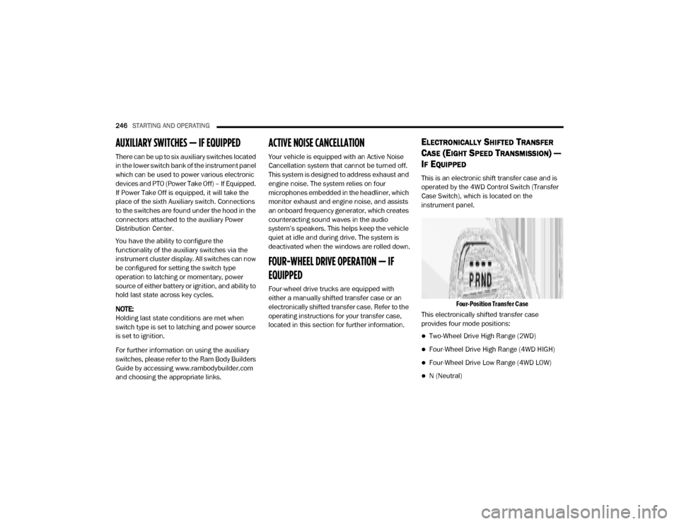
Four-Position Transfer Case
This electronically shifted transfer case
provides four mode positions:
Two-Wheel Drive High Range (2WD)
Four-Wheel Drive High Range (4WD HIGH)
Four-Wheel Drive Low Range (4WD LOW)
N (Neutral)
20_DJD2_OM_EN_USC_t.book Page 246
Page 249 of 568
STARTING AND OPERATING247
For additional information on the appropriate
use of each transfer case mode position, see
the information below:
2WD
Two-Wheel Drive High Range — This range is for
normal street and highway driving on dry hard
surfaced roads.
4WD HIGH
Four-Wheel Drive High Range — This range
provides torque to the front driveshaft (engages
four-wheel drive) which allows front and rear
wheels to spin at the same speed. This provides
additional traction for loose, slippery road
surfaces only.
4WD LOW
Four-Wheel Drive Low Range — This range
provides low speed four-wheel drive. It
maximizes torque (increased torque over 4WD
HIGH) to the front driveshaft, allowing front and
rear wheels to rotate at the same speed. This
range provides additional traction and
maximum pulling power for loose, slippery road
surfaces only. Do not exceed 25 mph (40 km/h)
in this range. N (Neutral)
N (Neutral) — This range disengages both the
front and rear driveshafts from the powertrain.
To be used for flat towing behind another
vehicle. Refer to “Recreational Towing” in this
section for further information.
This electronically shifted transfer case is
designed to be driven in the two–wheel drive
position (2WD) for normal street and highway
conditions on dry hard surfaced roads. Driving
the vehicle in 2WD will have greater fuel
economy benefits as the front axle is not
engaged in 2WD.
When additional traction is required, the
transfer case 4WD HIGH and 4WD LOW
positions can be used to maximize torque to the
front driveshaft, forcing the front and rear
wheels to rotate at the same speed. This is
accomplished by pushing the desired position
on the 4WD control switch.
Refer to “Shifting Procedure” in this section for
specific shifting instructions.
The 4WD HIGH and 4WD LOW positions are
designed for loose, slippery road surfaces only.
Driving in the 4WD HIGH and 4WD LOW
positions on dry hard surfaced roads may cause
increased tire wear and damage to the driveline
components.
WARNING!
You or others could be injured or killed if you
leave the vehicle unattended with the
transfer case in the NEUTRAL (N) position
without first fully engaging the parking brake.
The transfer case NEUTRAL (N) position
disengages both the front and rear drive
shaft from the powertrain, and will allow the
vehicle to roll, even if the transmission is in
PARK. The parking brake should always be
applied when the driver is not in the vehicle.
The transmission may not engage PARK if the
vehicle is moving. Always bring the vehicle to
a complete stop before shifting to PARK, and
verify that the transmission gear position indi
-
cator solidly indicates PARK (P) without
blinking. Ensure that the vehicle is completely
stopped, and the PARK position is properly
indicated, before exiting the vehicle.
5
20_DJD2_OM_EN_USC_t.book Page 247
Page 250 of 568

248STARTING AND OPERATING
NOTE:
The transfer case NEUTRAL button is located in
the center of the 4WD Control Switch and is
pushed by using a ballpoint pen or similar
object. The transfer case NEUTRAL position is to
be used for recreational towing only. Refer to
“Recreational Towing” in “Starting And Oper -
ating” for further information.
Transfer Case Position Indicator Lights
The Transfer Case Position Indicator Lights
(4WD HIGH and 4WD LOW) are located in the
instrument cluster and indicate the current and
desired transfer case selection. When you
select a different transfer case position, the
indicator lights will do the following:
If All Of The Following Shift Conditions Are Met:
1. The current position indicator light will turn off.
2. The selected position indicator light will flash until the transfer case completes the
shift.
3. When the shift is complete, the indicator light for the selected position will stop
flashing and remain on. If One Or More Of The Following Shift Conditions
Are Not Met:
1. The indicator light for the current position
will remain on.
2. The newly selected position indicator light will continue to flash.
3. The transfer case will not shift.
NOTE:
Before retrying a selection, make certain that all
the necessary requirements for selecting a new
transfer case position have been met. To retry the
selection, push the current position, wait five
seconds, and retry selection. To find the shift
requirements, refer to the “Shifting Procedure”
for your transfer case, located in this section.
The “SVC 4WD Warning Light” monitors the
electronic shift four-wheel drive system. If this
light remains on after engine start up or
illuminates during driving, it means that the
four-wheel drive system is not functioning
properly and that service is required.
NOTE:
Do not attempt to make a shift while only the
front or rear wheels are spinning. This could
cause damage to driveline components. When operating your vehicle in 4WD LOW, the
engine speed is approximately three times that
of the 2WD or 4WD HIGH positions at a given
road speed. Take care not to overspeed the
engine and do not exceed 25 mph (40 km/h).
Proper operation of four-wheel drive vehicles
depends on tires of equal size, type and
circumference on each wheel. Any difference in
tire size can cause damage to the drivetrain.
Because four-wheel drive provides improved
traction, there is a tendency to exceed safe
turning and stopping speeds. Do not go faster
than road conditions permit.
Shifting Procedure
NOTE:
If any of the requirements to select a new
transfer case position have not been met, the
transfer case will not shift. The position indi
-
cator light for the previous position will
remain on and the newly selected position
indicator light will continue to flash until all
the requirements for the selected position
have been met.
If all the requirements to select a new
transfer case position have been met, the
20_DJD2_OM_EN_USC_t.book Page 248