USB port Ram 3500 2020 Owner's Manual
[x] Cancel search | Manufacturer: RAM, Model Year: 2020, Model line: 3500, Model: Ram 3500 2020Pages: 568
Page 12 of 568
10
MULTIMEDIA
UCONNECT SYSTEMS ....................................... 467
CYBERSECURITY ............................................... 467
UCONNECT SETTINGS ....................................... 468
Uconnect 3 Settings ..................................468Uconnect 4/4C/4C NAV Settings .............484
Uconnect 4C NAV With 12-inch
Display Settings .........................................505
SAFETY AND GENERAL INFORMATION .......... 524
Safety Guidelines .......................................524
UCONNECT 3 WITH 5-INCH DISPLAY .............. 525
Introduction ................................................525
Radio Mode ................................................526
Media Mode ...............................................529Phone Mode ...............................................531
STEERING WHEEL AUDIO CONTROLS —
IF EQUIPPED ...................................................... 537
Radio Operation .........................................538
Media Mode ...............................................538
IPOD®/USB/MP3 CONTROL — IF EQUIPPED .. 538
RADIO OPERATION AND MOBILE PHONES ...540
Regulatory And Safety Information........... 540
VOICE RECOGNITION QUICK TIPS ................... 541
Introducing Uconnect ................................ 541
Get Started ................................................. 541
Basic Voice Commands............................. 542Radio .......................................................... 543
Media.......................................................... 543
Phone ......................................................... 543Voice Text Reply — If Equipped ................. 543
Climate (4C/4C NAV) ................................. 544
Navigation (4C NAV) .................................. 544Siri® Eyes Free — If Equipped ................. 545
Using Do Not Disturb ................................ 545
Android Auto™ — If Equipped ................... 545
Apple CarPlay® — If Equipped ................. 546
General Information .................................. 546Additional Information ............................... 547
CUSTOMER ASSISTANCE
SUGGESTIONS FOR OBTAINING SERVICE
FOR YOUR VEHICLE .......................................... 548
Prepare For The Appointment .................. 548Prepare A List............................................. 548
Be Reasonable With Requests ................. 548
IF YOU NEED ASSISTANCE .............................. 548
FCA US LLC Customer Center ................... 549
FCA Canada Inc. Customer Center ........... 549
In Mexico Contact ...................................... 549
Puerto Rico And US Virgin Islands ............ 549
Customer Assistance For The Hearing
Or Speech Impaired (TDD/TTY) ................ 549 Service Contract ....................................... 549
WARRANTY INFORMATION .............................. 550
MOPAR PARTS................................................... 550
REPORTING SAFETY DEFECTS ........................ 550
In The 50 United States And
Washington, D.C. ....................................... 550 In Canada ................................................... 550
PUBLICATION ORDER FORMS ........................ 551
20_DJD2_OM_EN_USC_t.book Page 10
Page 84 of 568

82GETTING TO KNOW YOUR VEHICLE
Pull on the upper handle on the front of the
armrest to raise the cover. The upper storage
area contains a USB power outlet located at the
rear of the area that can be used to power small
electrical devices, refer to “Electrical Power
Outlets” in this section for further information.
With the upper lid closed, pull on the lower
handle to open the lower storage bin. The lower
bin contains a power inverter outlet located in
the forward portion of the lower bin. There is
also a “fill line” located along the rear inside wall of the lower bin. Contents above the “fill
line” may interfere with cupholder placement if
equipped with a premium center console.
Forward Portion Of Lower Storage Bin
Premium Center Console — If Equipped
The premium center console is equipped with
two front storage bins located in front of the
center storage compartment. These storage
bins may be equipped with tandem doors. Push
the front bin to access the cupholders. Or push
the rear bin to access the coinholder/small
storage bin.
Center Console Tandem Doors— If Equipped
WARNING!
This armrest is not a seat. Anyone seated
on the armrest could be seriously injured
during vehicle operation, or a collision. Only
use the center seating position when the
armrest is fully upright.
In a collision, the latch may open if the total
weight of the items stored exceeds about
10 lbs (4.5 kg). These items could be
thrown about endangering occupants of
the vehicle. Items stored should not exceed
a total of 10 lbs (4.5 kg).
1 — Wireless Charging Pad
2 — Power Inverter
3 — Storage Area
WARNING!
Do not operate this vehicle with a console
compartment lid in the open position. Driving
with the console compartment lid open may
result in injury in a collision.
1 — Push Front Bin Access
2 — Push Rear Bin Access
20_DJD2_OM_EN_USC_t.book Page 82
Page 88 of 568

86GETTING TO KNOW YOUR VEHICLE
CUPHOLDERS
Front Seat Cupholders
For vehicles equipped with a center console,
two cupholders are located in front of the
console storage bin.
Front Cupholders
NOTE:
If the vehicle is equipped with a premium center
console with double (tandem) doors, push the
front bin door to access the cupholders.
Vehicles Equipped With 40/20/40 Seats
The cupholders are located on the backside of
the center portion of the front seat (20). Fold
down the center section of the front seat to gain
access to the cupholders.
Front Cupholders With Bench Seat
Rear Cupholders — If Equipped
Some vehicles are equipped with rear
cupholders located in the center armrest.
Rear Armrest Cupholder
Some vehicles may be equipped with a rear
cupholder that consists of two cup wells for rear
passenger convenience.
Rear Cup Wells
ELECTRICAL POWER OUTLETS
The auxiliary 12 Volt (13 Amp) power outlet can
provide power for in-cab accessories designed
for use with the standard “cigar lighter” plug.
The 12 Volt power outlets and 5 Volt (2.5 Amp)
USB Port (Charge Only) have a cap attached to
the outlet indicating “12V DC”, together with
either a key symbol, battery symbol, or USB
symbol.
A key symbol indicates that the key must be in
the ON/RUN or ACC position for the outlet to
provide power. The battery symbol indicates
that the outlet is connected to the battery, and
can provide power at all times.
20_DJD2_OM_EN_USC_t.book Page 86
Page 89 of 568
GETTING TO KNOW YOUR VEHICLE87
(Continued)
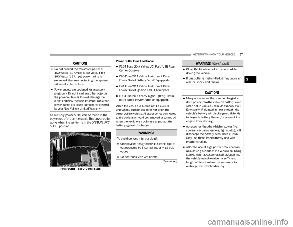
An auxiliary power outlet can be found in the
tray on top of the center stack. This power outlet
works when the ignition is in the ON/RUN, ACC,
or OFF position.
Power Outlet — Top Of Center Stack
Power Outlet Fuse Locations:
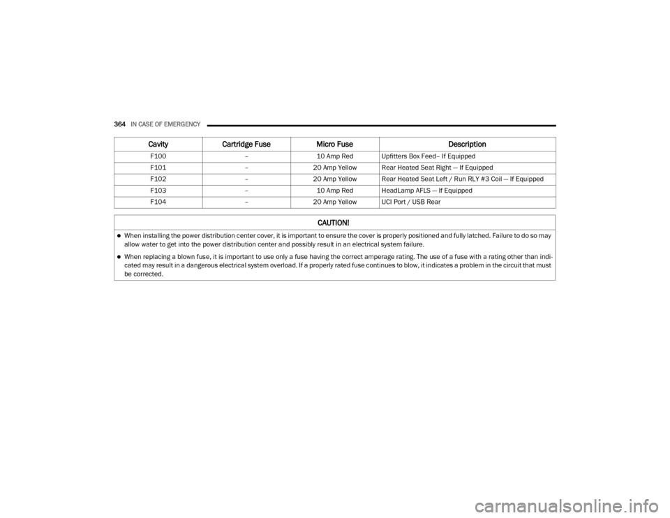
F104 Fuse 20 A Yellow UCI Port/ USB Rear
Center Console
F90 Fuse 20 A Yellow Instrument Panel
Power Outlet Battery Fed (If Equipped)
F91 Fuse 20 A Yellow Instrument Panel
Power Outlet Ignition Fed (If Equipped)
F93 Fuse 20 A Yellow Cigar Lighter/ Instru
-
ment Panel Power Outlet (If Equipped)
When the vehicle is turned off, be sure to
unplug any equipment as to not drain the
battery of the vehicle. All accessories connected
to the outlet(s) should be removed or turned off
when the vehicle is not in use to protect the
battery against discharge.
CAUTION!
Do not exceed the maximum power of
160 Watts (13 Amps) at 12 Volts. If the
160 Watts (13 Amps) power rating is
exceeded, the fuse protecting the system
will need to be replaced.
Power outlets are designed for accessory
plugs only. Do not insert any other object in
the power outlets as this will damage the
outlet and blow the fuse. Improper use of the
power outlet can cause damage not covered
by your New Vehicle Limited Warranty.
WARNING!
To avoid serious injury or death:
Only devices designed for use in this type of
outlet should be inserted into any 12 Volt
outlet.
Do not touch with wet hands.
Close the lid when not in use and while
driving the vehicle.
If this outlet is mishandled, it may cause an
electric shock and failure.
CAUTION!
Many accessories that can be plugged in
draw power from the vehicle's battery, even
when not in use (i.e., cellular phones, etc.).
Eventually, if plugged in long enough, the
vehicle's battery will discharge sufficiently
to degrade battery life and/or prevent the
engine from starting.
Accessories that draw higher power (i.e.,
coolers, vacuum cleaners, lights, etc.), will
discharge the battery even more quickly.
Only use these intermittently and with
greater caution.
After the use of high power draw accesso -
ries, or long periods of the vehicle not being
started (with accessories still plugged in),
the vehicle must be driven a sufficient
length of time to allow the generator to
recharge the vehicle's battery.
WARNING! (Continued)
2
20_DJD2_OM_EN_USC_t.book Page 87
Page 131 of 568

GETTING TO KNOW YOUR INSTRUMENT PANEL129
demanding hot or high altitude conditions. If the
instrument cluster display displays the
message “Active Airbox Service Required See
Dealer”, vehicle performance may be reduced
until service is performed by an authorized RAM
dealer.
BATTERY SAVER ON/BATTERY SAVER
M
ODE MESSAGE — ELECTRICAL LOAD
R
EDUCTION ACTIONS — IF EQUIPPED
This vehicle is equipped with an Intelligent
Battery Sensor (IBS) to perform additional
monitoring of the electrical system and status
of the vehicle battery.
In cases when the IBS detects charging system
failure, or the vehicle battery conditions are
deteriorating, electrical load reduction actions
will take place to extend the driving time and
distance of the vehicle. This is done by reducing
power to or turning off non-essential electrical
loads.
Load reduction is only active when the engine is
running. It will display a message if there is a
risk of battery depletion to the point where the
vehicle may stall due to lack of electrical supply,
or will not restart after the current drive cycle. When load reduction is activated, the message
“Battery Saver On Some Systems May Have
Reduced Power” will appear in the instrument
cluster.
These messages indicate the vehicle battery
has a low state of charge and continues to lose
electrical charge at a rate that the charging
system cannot sustain.
NOTE:The charging system is independent from
load reduction. The charging system
performs a diagnostic on the charging
system continuously.
If the Battery Charge Warning Light is on it
may indicate a problem with the charging
system. Refer to “Warning Lights And
Messages” in “Getting To Know Your Instru
-
ment Panel” for further information.
The electrical loads that may be switched off (if
equipped), and vehicle functions which can be
affected by load reduction:
Heated Seats/Vented Seats/Heated Wheel
Rear Defroster And Heated Mirrors
HVAC System
115 Volts AC Power Inverter System
Audio and Telematics System
Loss of the battery charge may indicate one or
more of the following conditions:
The charging system cannot deliver enough
electrical power to the vehicle system
because the electrical loads are larger than
the capability of charging system. The
charging system is still functioning properly.
Turning on all possible vehicle electrical
loads (e.g. HVAC to max settings, exterior and
interior lights, overloaded power outlets
+12 Volts, 115 Volts AC, USB ports) during
certain driving conditions (city driving,
towing, frequent stopping).
Installing options like additional lights,
upfitter electrical accessories, audio
systems, alarms and similar devices.
Unusual driving cycles (short trips separated
by long parking periods).
The vehicle was parked for an extended
period of time (weeks, months).
3
20_DJD2_OM_EN_USC_t.book Page 129
Page 132 of 568
130GETTING TO KNOW YOUR INSTRUMENT PANEL
The battery was recently replaced and was
not charged completely.
The battery was discharged by an electrical
load left on when the vehicle was parked.
The battery was used for an extended period
with the engine not running to supply radio,
lights, chargers, +12 Volts portable appli-
ances like vacuum cleaners, game consoles
and similar devices.
What to do when an electrical load reduction
action message is present (“Battery Saver On”
or “Battery Saver Mode”)
During a trip:
Reduce power to unnecessary loads if
possible:
Turn off redundant lights (interior or
exterior).
Check what may be plugged in to power
outlets +12 Volts, 115 Volts AC, USB
ports.
Check HVAC settings (blower, tempera -
ture).
Check the audio settings (volume). After a trip:
Check if any aftermarket equipment was
installed (additional lights, upfitter electrical
accessories, audio systems, alarms) and
review specifications if any (load and Ignition
Off Draw currents).
Evaluate the latest driving cycles (distance,
driving time and parking time).
The vehicle should have service performed if
the message is still present during consecu
-
tive trips and the evaluation of the vehicle
and driving pattern did not help to identify the
cause.
WARNING LIGHTS AND MESSAGES
The warning/indicator lights will illuminate in
the instrument panel together with a dedicated
message and/or acoustic signal when
applicable. These indications are indicative and
precautionary and as such must not be
considered as exhaustive. Always refer to the
information in this chapter in the event of a
failure indication. All active telltales will display
first if applicable. The system check menu may
appear different based upon equipment
options and current vehicle status. Some
telltales are optional and may not appear.
RED WARNING LIGHTS
Seat Belt Reminder Warning Light
This warning light indicates when the
driver or passenger seat belt is
unbuckled. When the ignition is first
placed in the ON/RUN or ACC/ON/
RUN position and if the driver’s seat belt is
unbuckled, a chime will sound and the light will
turn on. When driving, if the driver or front
passenger seat belt remains unbuckled, the
Seat Belt Reminder Light will flash or remain on
continuously and a chime will sound.
Refer to “Occupant Restraint Systems” in
“Safety” for further information.
Air Bag Warning Light
This warning light will illuminate to
indicate a fault with the air bag, and
will turn on for four to eight seconds
as a bulb check when the ignition is
placed in the ON/RUN or ACC/ON/RUN
position. This light will illuminate with a single
chime when a fault with the air bag has been
detected, it will stay on until the fault is cleared.
If the light is either not on during startup, stays
20_DJD2_OM_EN_USC_t.book Page 130
Page 364 of 568
362IN CASE OF EMERGENCY
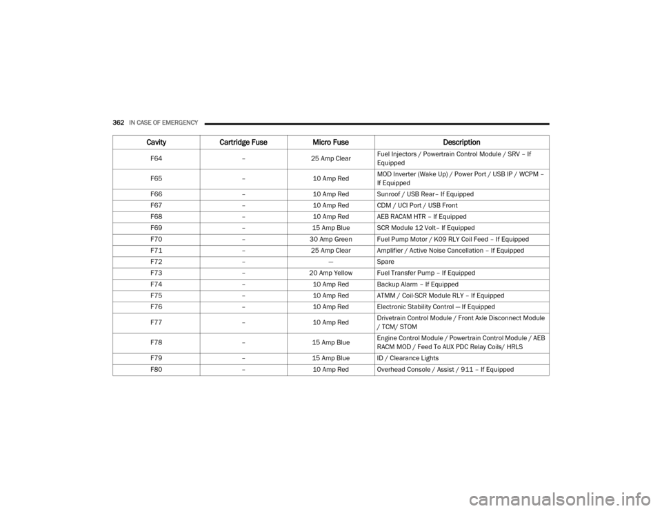
F64 –25 Amp ClearFuel Injectors / Powertrain Control Module / SRV – If
Equipped
F65 –10 Amp RedMOD Inverter (Wake Up) / Power Port / USB IP / WCPM –
If Equipped
F66 –10 Amp Red Sunroof / USB Rear– If Equipped
F67 –10 Amp Red CDM / UCI Port / USB Front
F68 –10 Amp Red AEB RACAM HTR – If Equipped
F69 –15 Amp Blue SCR Module 12 Volt– If Equipped
F70 –30 Amp Green Fuel Pump Motor / K09 RLY Coil Feed – If Equipped
F71 –25 Amp Clear Amplifier / Active Noise Cancellation – If Equipped
F72 –—Spare
F73 –20 Amp Yellow Fuel Transfer Pump – If Equipped
F74 –10 Amp Red Backup Alarm – If Equipped
F75 –10 Amp Red ATMM / Coil-SCR Module RLY – If Equipped
F76 –10 Amp Red Electronic Stability Control — If Equipped
F77 –10 Amp RedDrivetrain Control Module / Front Axle Disconnect Module
/ TCM/ STOM
F78 –15 Amp BlueEngine Control Module / Powertrain Control Module / AEB
RACM MOD / Feed To AUX PDC Relay Coils/ HRLS
F79 –15 Amp Blue ID / Clearance Lights
F80 –10 Amp Red Overhead Console / Assist / 911 – If Equipped
CavityCartridge Fuse Micro Fuse Description
20_DJD2_OM_EN_USC_t.book Page 362
Page 366 of 568
364IN CASE OF EMERGENCY
F100 –10 Amp Red Upfitters Box Feed– If Equipped
F101 –20 Amp Yellow Rear Heated Seat Right — If Equipped
F102 –20 Amp Yellow Rear Heated Seat Left / Run RLY #3 Coil — If Equipped
F103 –10 Amp Red HeadLamp AFLS — If Equipped
F104 –20 Amp Yellow UCI Port / USB Rear
CavityCartridge Fuse Micro Fuse Description
CAUTION!
When installing the power distribution center cover, it is important to ensure the cover is properly positioned and fully latched. Failure to do so may
allow water to get into the power distribution center and possibly result in an electrical system failure.
When replacing a blown fuse, it is important to use only a fuse having the correct amperage rating. The use of a fuse with a rating other than indi -
cated may result in a dangerous electrical system overload. If a properly rated fuse continues to blow, it indicates a problem in the circuit that must
be corrected.
20_DJD2_OM_EN_USC_t.book Page 364
Page 530 of 568
528MULTIMEDIA
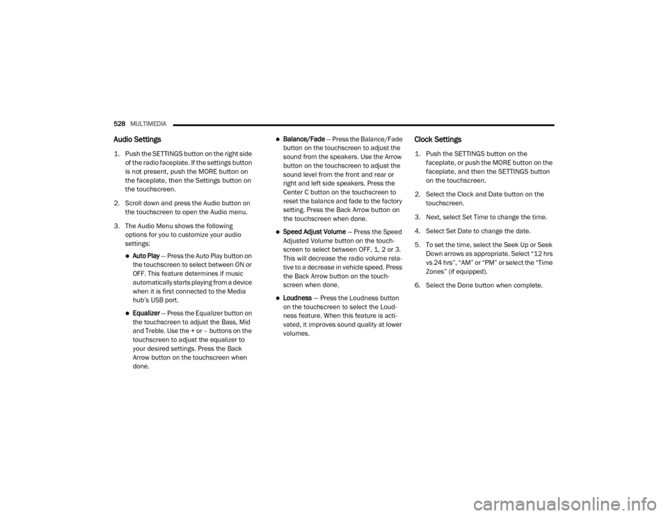
Audio Settings
1. Push the SETTINGS button on the right side
of the radio faceplate. If the settings button
is not present, push the MORE button on
the faceplate, then the Settings button on
the touchscreen.
2. Scroll down and press the Audio button on the touchscreen to open the Audio menu.
3. The Audio Menu shows the following options for you to customize your audio
settings:
Auto Play — Press the Auto Play button on
the touchscreen to select between ON or
OFF. This feature determines if music
automatically starts playing from a device
when it is first connected to the Media
hub’s USB port.
Equalizer — Press the Equalizer button on
the touchscreen to adjust the Bass, Mid
and Treble. Use the + or – buttons on the
touchscreen to adjust the equalizer to
your desired settings. Press the Back
Arrow button on the touchscreen when
done.
Balance/Fade — Press the Balance/Fade
button on the touchscreen to adjust the
sound from the speakers. Use the Arrow
button on the touchscreen to adjust the
sound level from the front and rear or
right and left side speakers. Press the
Center C button on the touchscreen to
reset the balance and fade to the factory
setting. Press the Back Arrow button on
the touchscreen when done.
Speed Adjust Volume — Press the Speed
Adjusted Volume button on the touch -
screen to select between OFF, 1, 2 or 3.
This will decrease the radio volume rela -
tive to a decrease in vehicle speed. Press
the Back Arrow button on the touch-
screen when done.
Loudness — Press the Loudness button
on the touchscreen to select the Loud -
ness feature. When this feature is acti -
vated, it improves sound quality at lower
volumes.
Clock Settings
1. Push the SETTINGS button on the faceplate, or push the MORE button on the
faceplate, and then the SETTINGS button
on the touchscreen.
2. Select the Clock and Date button on the touchscreen.
3. Next, select Set Time to change the time.
4. Select Set Date to change the date.
5. To set the time, select the Seek Up or Seek Down arrows as appropriate. Select “12 hrs
vs 24 hrs”, “AM” or “PM” or select the “Time
Zones” (if equipped).
6. Select the Done button when complete.
20_DJD2_OM_EN_USC_t.book Page 528
Page 532 of 568
530MULTIMEDIA
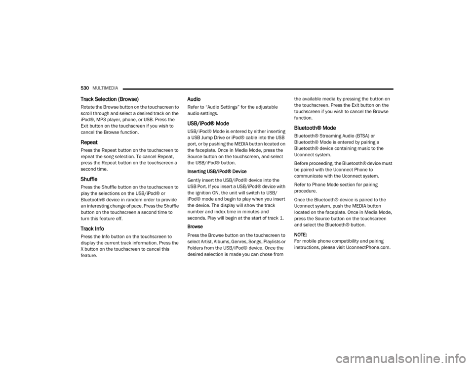
Track Selection (Browse)
Rotate the Browse button on the touchscreen to
scroll through and select a desired track on the
iPod®, MP3 player, phone, or USB. Press the
Exit button on the touchscreen if you wish to
cancel the Browse function.
Repeat
Press the Repeat button on the touchscreen to
repeat the song selection. To cancel Repeat,
press the Repeat button on the touchscreen a
second time.
Shuffle
Press the Shuffle button on the touchscreen to
play the selections on the USB/iPod® or
Bluetooth® device in random order to provide
an interesting change of pace. Press the Shuffle
button on the touchscreen a second time to
turn this feature off.
Track Info
Press the Info button on the touchscreen to
display the current track information. Press the
X button on the touchscreen to cancel this
feature.
Audio
Refer to “Audio Settings” for the adjustable
audio settings.
USB/iPod® Mode
USB/iPod® Mode is entered by either inserting
a USB Jump Drive or iPod® cable into the USB
port, or by pushing the MEDIA button located on
the faceplate. Once in Media Mode, press the
Source button on the touchscreen, and select
the USB/iPod® button.
Inserting USB/iPod® Device
Gently insert the USB/iPod® device into the
USB Port. If you insert a USB/iPod® device with
the ignition ON, the unit will switch to USB/
iPod® mode and begin to play when you insert
the device. The display will show the track
number and index time in minutes and
seconds. Play will begin at the start of track 1.
Browse
Press the Browse button on the touchscreen to
select Artist, Albums, Genres, Songs, Playlists or
Folders from the USB/iPod® device. Once the
desired selection is made you can chose from the available media by pressing the button on
the touchscreen. Press the Exit button on the
touchscreen if you wish to cancel the Browse
function.Bluetooth® Mode
Bluetooth® Streaming Audio (BTSA) or
Bluetooth® Mode is entered by pairing a
Bluetooth® device containing music to the
Uconnect system.
Before proceeding, the Bluetooth® device must
be paired with the Uconnect Phone to
communicate with the Uconnect system.
Refer to Phone Mode section for pairing
procedure.
Once the Bluetooth® device is paired to the
Uconnect system, push the MEDIA button
located on the faceplate. Once in Media Mode,
press the Source button on the touchscreen
and select the Bluetooth® button.
NOTE:
For mobile phone compatibility and pairing
instructions, please visit UconnectPhone.com.
20_DJD2_OM_EN_USC_t.book Page 530