charging Ram 3500 2020 Owner's Manual
[x] Cancel search | Manufacturer: RAM, Model Year: 2020, Model line: 3500, Model: Ram 3500 2020Pages: 568
Page 6 of 568
4
GARAGE DOOR OPENER — IF EQUIPPED .........76 Before You Begin Programming
HomeLink® .................................................. 76 Canadian/Gate Operator Programming ..... 79
Using HomeLink® ........................................ 79
Security......................................................... 80
Troubleshooting Tips ................................... 80
General Information .................................... 80
INTERNAL EQUIPMENT ........................................81
Storage ......................................................... 81
Cupholders .................................................. 86
Electrical Power Outlets .............................. 86
Power Inverter — If Equipped ..................... 88
Wireless Charging Pad — If Equipped ........ 89
Overhead Sunglass Storage........................ 90
PICKUP BOX .........................................................90
Cargo Camera — If Equipped ...................... 91
RAMBOX — IF EQUIPPED .....................................92
RamBox Integrated Box Side
Storage Bins ................................................. 92 RamBox Safety Warning .............................. 94
Bed Divider — If Equipped ........................... 94
Bed Rail Tie-Down System — If Equipped .. 96
SLIDE-IN CAMPERS .............................................98
Camper Applications ................................... 98 EASY-OFF TAILGATE ........................................... 98
Disconnecting The Rear Camera And
Remote Keyless Entry ................................. 98 Removing The Tailgate ................................ 99
Locking Tailgate ........................................... 99
TRI-FOLD TONNEAU COVER — IF EQUIPPED ..100
Tri-Fold Tonneau Cover Removal.............. 100
Tri-Fold Tonneau Cover Installation.......... 102Tri-Fold Tonneau Cover Cleaning .............. 105
GETTING TO KNOW YOUR
INSTRUMENT PANEL
BASE / MIDLINE INSTRUMENT CLUSTER —
GAS ENGINE........................................................ 106
Base / Midline Instrument Cluster
Descriptions — Gas Engine ....................... 106
PREMIUM INSTRUMENT CLUSTER —
GAS ENGINE........................................................ 108
Premium Instrument Cluster
Descriptions — Gas Engine ....................... 108
BASE INSTRUMENT CLUSTER —
DIESEL ENGINE ................................................. 110
Base Instrument Cluster Descriptions —
Diesel Engine ............................................. 110 PREMIUM INSTRUMENT CLUSTER —
DIESEL ENGINE .................................................. 112
Premium Instrument Cluster
Descriptions — Diesel Engine ................... 112
INSTRUMENT CLUSTER DISPLAY ................... 113
Instrument Cluster Display Controls ........ 114
Oil Life Reset ............................................. 115
Display Menu Items ................................... 116
Diesel Messages And Warnings — 6.7L
Cummins Diesel Engine ............................ 125 Battery Saver On/Battery Saver Mode
Message — Electrical Load Reduction
Actions — If Equipped ............................... 129
WARNING LIGHTS AND MESSAGES ............... 130
Red Warning Lights ................................... 130
Yellow Warning Lights ............................... 133Yellow Indicator Lights .............................. 138
Green Indicator Lights ............................... 140White Indicator Lights ............................... 141Blue Indicator Lights ................................. 142
ONBOARD DIAGNOSTIC SYSTEM — OBD II ... 142
Onboard Diagnostic System
(OBD II) Cybersecurity ............................... 142
EMISSIONS INSPECTION AND MAINTENANCE
PROGRAMS ....................................................... 143
20_DJD2_OM_EN_USC_t.book Page 4
Page 16 of 568
14GETTING TO KNOW YOUR VEHICLE
TIP:
When viewing a topic, tap the star icon to add it
to your Favorites, for easy access in the future.
KEYS
KEY FOB
Your vehicle uses a keyless ignition system. The
ignition system consists of a key fob and a
START/STOP push button ignition system. The
Remote Keyless Entry (RKE) system consists of
a key fob and Keyless Enter-N-Go feature.
NOTE:
The key fob may not be found if it is located next
to a mobile phone, laptop or other electronic
device; these devices may block the key fob’s
wireless signal.
The key fob allows you to lock or unlock all
doors, tailgate, and the RamBox (if equipped),
as well as release the tailgate, and activate the
Panic Alarm from distances up to approximately
66 ft (20 m). The key fob does not need to be
pointed at the vehicle to activate the system.
NOTE:
In the ON/RUN position, all key fob buttons
will work until the vehicle reaches 2 mph
(4 km/h).
The key fob should not be placed next to the
wireless charging pad (if equipped).
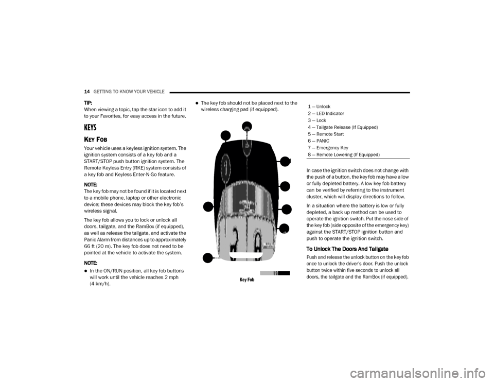
Key Fob
In case the ignition switch does not change with
the push of a button, the key fob may have a low
or fully depleted battery. A low key fob battery
can be verified by referring to the instrument
cluster, which will display directions to follow.
In a situation where the battery is low or fully
depleted, a back up method can be used to
operate the ignition switch. Put the nose side of
the key fob (side opposite of the emergency key)
against the START/STOP ignition button and
push to operate the ignition switch.
To Unlock The Doors And Tailgate
Push and release the unlock button on the key fob
once to unlock the driver’s door. Push the unlock
button twice within five seconds to unlock all
doors, the tailgate and the RamBox (if equipped).
1 — Unlock
2 — LED Indicator
3 — Lock
4 — Tailgate Release (If Equipped)
5 — Remote Start
6 — PANIC
7 — Emergency Key
8 — Remote Lowering (If Equipped)
20_DJD2_OM_EN_USC_t.book Page 14
Page 84 of 568

82GETTING TO KNOW YOUR VEHICLE
Pull on the upper handle on the front of the
armrest to raise the cover. The upper storage
area contains a USB power outlet located at the
rear of the area that can be used to power small
electrical devices, refer to “Electrical Power
Outlets” in this section for further information.
With the upper lid closed, pull on the lower
handle to open the lower storage bin. The lower
bin contains a power inverter outlet located in
the forward portion of the lower bin. There is
also a “fill line” located along the rear inside wall of the lower bin. Contents above the “fill
line” may interfere with cupholder placement if
equipped with a premium center console.
Forward Portion Of Lower Storage Bin
Premium Center Console — If Equipped
The premium center console is equipped with
two front storage bins located in front of the
center storage compartment. These storage
bins may be equipped with tandem doors. Push
the front bin to access the cupholders. Or push
the rear bin to access the coinholder/small
storage bin.
Center Console Tandem Doors— If Equipped
WARNING!
This armrest is not a seat. Anyone seated
on the armrest could be seriously injured
during vehicle operation, or a collision. Only
use the center seating position when the
armrest is fully upright.
In a collision, the latch may open if the total
weight of the items stored exceeds about
10 lbs (4.5 kg). These items could be
thrown about endangering occupants of
the vehicle. Items stored should not exceed
a total of 10 lbs (4.5 kg).
1 — Wireless Charging Pad
2 — Power Inverter
3 — Storage Area
WARNING!
Do not operate this vehicle with a console
compartment lid in the open position. Driving
with the console compartment lid open may
result in injury in a collision.
1 — Push Front Bin Access
2 — Push Rear Bin Access
20_DJD2_OM_EN_USC_t.book Page 82
Page 90 of 568

88GETTING TO KNOW YOUR VEHICLE
POWER INVERTER — IF EQUIPPED
If equipped, a 115 Volt (400 Watts maximum)
inverter may be located inside the center
console toward the right hand side, just under
the Wireless Charging Pad (if equipped). This
inverter can power cellular phones, electronics
and other low power devices requiring power up
to 400 Watts. Certain high-end video game
consoles exceed this power limit, as will most
power tools.
Center Console Power Inverter Outlet
There is also a second 115 Volt (400 Watts
maximum) power inverter located on the rear of
the center console. This inverter can power
cellular phones, electronics and other low
power devices requiring power up to 400 Watts. Certain high-end video game consoles exceed
this power limit, as will most power tools.
All power inverters are designed with built-in
overload protection. If the power rating of
400 Watts is exceeded, the power inverter
shuts down. Once the electrical device has
been removed from the outlet the inverter
should reset.
Rear Center Console Power Inverter Outlet
NOTE:
400 Watts is the maximum for the inverter, not
each outlet. If three outlets are in use, 400 Watts
is shared amongst the devices plugged in.
If your vehicle is equipped with a Ram Box, a
115 Volt (400 Watts Maximum) inverter will be
located inside the Ram Box. The inverter can be
turned on by the Instrument Panel Power Inverter switch located to the left of the steering
wheel. This inverter can power cellular phones,
electronics and other low power devices
requiring power up to 400 Watts. Certain
high-end video game consoles exceed this
power limit, as will most power tools.
Ram Box Power Inverter
Instrument Panel Power Inverter Switch
20_DJD2_OM_EN_USC_t.book Page 88
Page 91 of 568

GETTING TO KNOW YOUR VEHICLE89
If equipped, there may be a 115 Volt (400 Watts
maximum) inverter located to the right of the
center stack, just below the climate controls.
This inverter can power cellular phones,
electronics and other low power devices
requiring power up to 400 Watts. Certain
high-end video game consoles exceed this
power limit, as will most power tools.
Center Stack Power Inverter
To turn on the power outlet, simply plug in the
device. The outlet turns off when the device is
unplugged.
NOTE:
The Power Inverter only turns on if the igni -
tion is in the ACC or ON/RUN mode.
Due to built-in overload protection, the power
inverter shuts down if the power rating is
exceeded.
WIRELESS CHARGING PAD — IF
E
QUIPPED
Wireless Charging Pad Your vehicle may be equipped with a 15W 3A Qi
wireless charging pad located inside of the center
console. This charging pad is designed to
wirelessly charge your Qi enabled mobile phone.
Qi is a standard that uses magnetic induction to
transfer power to your mobile device.
Your mobile phone must be designed for Qi
wireless charging. If the phone is not equipped
with Qi wireless charging functionality, an
aftermarket sleeve or a specialized back plate
can be purchased from your mobile phone
provider or a local electronics retailer. Please
see your phone’s owner’s manual for further
information.
The wireless charging pad is equipped with an
anti-slip mat, an adjustable cradle to hold your
mobile phone in place and an LED indicator light.
WARNING!
To avoid serious injury or death:
Do not insert any objects into the receptacles.
Do not touch with wet hands.
Close the lid when not in use.
If this outlet is mishandled, it may cause an
electric shock and failure.
CAUTION!
The key fob should not be placed on the
charging pad or within 15 cm (150 mm) of it.
Doing so can cause excessive heat buildup
and damage to the fob. Placing the fob in
close proximity of the charging pad blocks the
fob from being detected by the vehicle and
prevents the vehicle from starting.
2
20_DJD2_OM_EN_USC_t.book Page 89
Page 131 of 568

GETTING TO KNOW YOUR INSTRUMENT PANEL129
demanding hot or high altitude conditions. If the
instrument cluster display displays the
message “Active Airbox Service Required See
Dealer”, vehicle performance may be reduced
until service is performed by an authorized RAM
dealer.
BATTERY SAVER ON/BATTERY SAVER
M
ODE MESSAGE — ELECTRICAL LOAD
R
EDUCTION ACTIONS — IF EQUIPPED
This vehicle is equipped with an Intelligent
Battery Sensor (IBS) to perform additional
monitoring of the electrical system and status
of the vehicle battery.
In cases when the IBS detects charging system
failure, or the vehicle battery conditions are
deteriorating, electrical load reduction actions
will take place to extend the driving time and
distance of the vehicle. This is done by reducing
power to or turning off non-essential electrical
loads.
Load reduction is only active when the engine is
running. It will display a message if there is a
risk of battery depletion to the point where the
vehicle may stall due to lack of electrical supply,
or will not restart after the current drive cycle. When load reduction is activated, the message
“Battery Saver On Some Systems May Have
Reduced Power” will appear in the instrument
cluster.
These messages indicate the vehicle battery
has a low state of charge and continues to lose
electrical charge at a rate that the charging
system cannot sustain.
NOTE:The charging system is independent from
load reduction. The charging system
performs a diagnostic on the charging
system continuously.
If the Battery Charge Warning Light is on it
may indicate a problem with the charging
system. Refer to “Warning Lights And
Messages” in “Getting To Know Your Instru
-
ment Panel” for further information.
The electrical loads that may be switched off (if
equipped), and vehicle functions which can be
affected by load reduction:
Heated Seats/Vented Seats/Heated Wheel
Rear Defroster And Heated Mirrors
HVAC System
115 Volts AC Power Inverter System
Audio and Telematics System
Loss of the battery charge may indicate one or
more of the following conditions:
The charging system cannot deliver enough
electrical power to the vehicle system
because the electrical loads are larger than
the capability of charging system. The
charging system is still functioning properly.
Turning on all possible vehicle electrical
loads (e.g. HVAC to max settings, exterior and
interior lights, overloaded power outlets
+12 Volts, 115 Volts AC, USB ports) during
certain driving conditions (city driving,
towing, frequent stopping).
Installing options like additional lights,
upfitter electrical accessories, audio
systems, alarms and similar devices.
Unusual driving cycles (short trips separated
by long parking periods).
The vehicle was parked for an extended
period of time (weeks, months).
3
20_DJD2_OM_EN_USC_t.book Page 129
Page 134 of 568
132GETTING TO KNOW YOUR INSTRUMENT PANEL
Hood Open Warning Light
This warning light will illuminate when
the hood is ajar/open and not fully
closed.
NOTE:
If the vehicle is moving, there will also be a
single chime.
Vehicle Security Warning Light — If
Equipped
This light will flash at a fast rate for
approximately 15 seconds when the
vehicle security alarm is arming, and
then will flash slowly until the vehicle
is disarmed.
Engine Coolant Temperature Warning
Light
This warning light warns of an
overheated engine condition. If the
engine coolant temperature is too
high, this indicator will illuminate and
a single chime will sound. If the temperature
reaches the upper limit, a continuous chime will
sound for four minutes or until the engine is
able to cool; whichever comes first. If the light turns on while driving, safely pull over
and stop the vehicle. If the Air Conditioning
(A/C) system is on, turn it off. Also, shift the
transmission into NEUTRAL and idle the vehicle.
If the temperature reading does not return to
normal, turn the engine off immediately and call
for service.
Refer to “If Your Engine Overheats” in “In Case
Of Emergency” for further information.
Battery Charge Warning Light
This warning light will illuminate when
the battery is not charging properly. If
it stays on while the engine is running,
there may be a malfunction with the
charging system. Contact an authorized dealer
as soon as possible.
This indicates a possible problem with the
electrical system or a related component.
Oil Pressure Warning Light
This warning light will illuminate to
indicate low engine oil pressure. If the
light turns on while driving, stop the
vehicle, shut off the engine as soon as
possible, and contact an authorized dealer. A
chime will sound when this light turns on. Do not operate the vehicle until the cause is
corrected. This light does not indicate how
much oil is in the engine. The engine oil level
must be checked under the hood.
Oil Temperature Warning Light
This warning light will illuminate to
indicate the engine oil temperature is
high. If the light turns on while driving,
stop the vehicle and shut off the
engine as soon as possible. Wait for oil
temperature to return to normal levels.
Electronic Throttle Control (ETC) Warning
Light
This warning light will illuminate to
indicate a problem with the Electronic
Throttle Control (ETC) system. If a
problem is detected while the vehicle
is running, the light will either stay on or flash
depending on the nature of the problem. Cycle
the ignition when the vehicle is safely and
completely stopped and the transmission is
placed in the PARK (P) position. The light should
turn off. If the light remains on with the vehicle
running, your vehicle will usually be drivable;
however, see an authorized dealer for service
as soon as possible.
20_DJD2_OM_EN_USC_t.book Page 132
Page 273 of 568

STARTING AND OPERATING271
Care should be taken to avoid sudden
accelerations when both rear wheels are on a
slippery surface. This could cause both rear
wheels to spin, and allow the vehicle to slide
sideways on the crowned surface of a road or in
a turn.
WINCH USAGE — POWER WAGON ONLY
(IF EQUIPPED)
THINGS TO KNOW BEFORE USING YOUR
W
INCH
General Winch Information
Your vehicle is equipped with an electric vehicle
recovery winch. This winch uses the electrical
power from the vehicle charging system to
power a motor that winds the winch rope onto
the winch drum via planetary gear reduction. By
nature, a winch is capable of generating very
high forces and should be used with care. Do
not operate the winch without reading and
understanding the complete winch owner's
manual.
Tensioning The Winch Rope
The winch rope must be properly tensioned
before use. Follow the instructions below to
tension the rope:
1. Un-spool the rope leaving five wraps of
rope on the winch drum.
2. Attach the hook to a suitable anchor point.
3. Apply at least 1,000 lbs (454 kg) of tension to the rope while winding the rope. Always
use care to ensure the rope does not pile up
on one side of the drum and is neatly wound
onto the drum.
Low Voltage Interrupt
Your winch is equipped with a device that will
interrupt winch function if the vehicle charging
system voltage drops to a low level. The winch
will not power-in or out for 30 seconds if this
device is tripped. If the interrupt is tripped, the
vehicle should be operated at high idle for a few
minutes to allow the vehicle charging system to
recover before continuing to winch.
UNDERSTANDING THE FEATURES OF
Y
OUR WINCH
Winch Components
1.
Motor:
The winch motor is powered by the
vehicle charging system.
CAUTION!
Be certain the anchor will withstand the load
required to tension the winch rope.
CAUTION!
The winch rope must spool on the winch
drum in the direction indicated on the drum
rotation decal on the winch.
5
20_DJD2_OM_EN_USC_t.book Page 271
Page 378 of 568
376IN CASE OF EMERGENCY
1. Apply the parking brake, shift the
automatic transmission into PARK and
turn the ignition OFF.
2. Turn off the heater, radio, and all unnecessary electrical accessories.
3. If using another vehicle to jump start the battery, park the vehicle within the jumper
cables’ reach, apply the parking brake and
make sure the ignition is OFF.
JUMP STARTING PROCEDURE
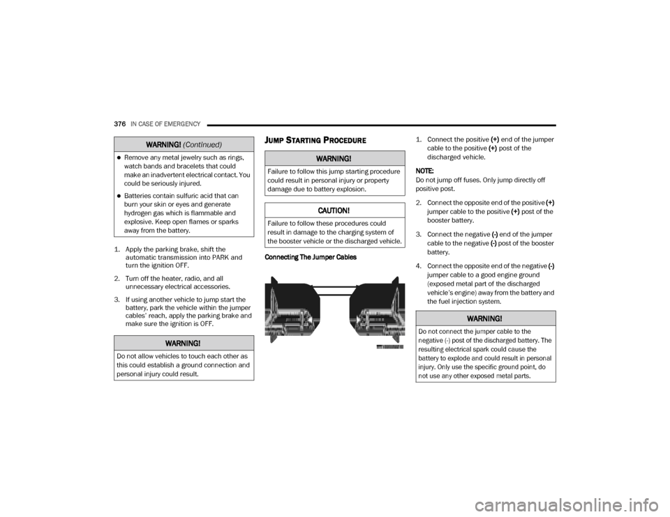
Connecting The Jumper Cables
1. Connect the positive
(+) end of the jumper
cable to the positive (+)
post of the
discharged vehicle.
NOTE:
Do not jump off fuses. Only jump directly off
positive post.
2. Connect the opposite end of the positive (+)
jumper cable to the positive (+) post of the
booster battery.
3. Connect the negative (-) end of the jumper
cable to the negative (-) post of the booster
battery.
4. Connect the opposite end of the negative (-)
jumper cable to a good engine ground
(exposed metal part of the discharged
vehicle’s engine) away from the battery and
the fuel injection system.
Remove any metal jewelry such as rings,
watch bands and bracelets that could
make an inadvertent electrical contact. You
could be seriously injured.
Batteries contain sulfuric acid that can
burn your skin or eyes and generate
hydrogen gas which is flammable and
explosive. Keep open flames or sparks
away from the battery.
WARNING!
Do not allow vehicles to touch each other as
this could establish a ground connection and
personal injury could result.
WARNING! (Continued)
WARNING!
Failure to follow this jump starting procedure
could result in personal injury or property
damage due to battery explosion.
CAUTION!
Failure to follow these procedures could
result in damage to the charging system of
the booster vehicle or the discharged vehicle.
WARNING!
Do not connect the jumper cable to the
negative (-) post of the discharged battery. The
resulting electrical spark could cause the
battery to explode and could result in personal
injury. Only use the specific ground point, do
not use any other exposed metal parts.
20_DJD2_OM_EN_USC_t.book Page 376
Page 379 of 568
IN CASE OF EMERGENCY377
5. Start the engine in the vehicle that has the
booster battery, let the engine idle a few
minutes, and then start the engine in the
vehicle with the discharged battery.
6. Once the engine is started, remove the jumper cables in the reverse sequence.
Disconnecting The Jumper Cables
1. Disconnect the negative
(-)
end of the
jumper cable from the engine ground of
the vehicle with the discharged battery.
2. Disconnect the opposite end of the negative (-) jumper cable from the negative (-) post of
the booster battery.
3. Disconnect the positive (+) end of the
jumper cable from the positive (+) post of
the booster battery.
4. Disconnect the opposite end of the positive (+) jumper cable from the positive (+) post
of the vehicle with the discharged battery.
If frequent jump starting is required to start your
vehicle you should have the battery and charging
system inspected at an authorized dealer.
GEAR SELECTOR OVERRIDE — 6–SPEED
TRANSMISSION
If a malfunction occurs and the gear selector
cannot be moved out of the PARK position, you
can use the following procedure to temporarily
move the gear selector:
1. Turn the engine OFF.
2. Firmly apply the parking brake.
3. Tilt the steering wheel to the full up position.
4. Press and maintain firm pressure on the
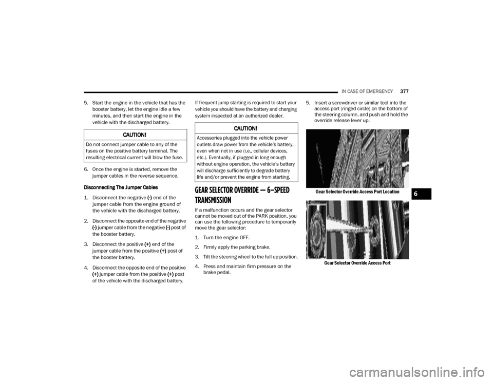
brake pedal. 5. Insert a screwdriver or similar tool into the
access port (ringed circle) on the bottom of
the steering column, and push and hold the
override release lever up.
Gear Selector Override Access Port Location Gear Selector Override Access Port
CAUTION!
Do not connect jumper cable to any of the
fuses on the positive battery terminal. The
resulting electrical current will blow the fuse.
CAUTION!
Accessories plugged into the vehicle power
outlets draw power from the vehicle’s battery,
even when not in use (i.e., cellular devices,
etc.). Eventually, if plugged in long enough
without engine operation, the vehicle’s battery
will discharge sufficiently to degrade battery
life and/or prevent the engine from starting.
6
20_DJD2_OM_EN_USC_t.book Page 377