diagnostic menu Ram 3500 2020 Owner's Manual
[x] Cancel search | Manufacturer: RAM, Model Year: 2020, Model line: 3500, Model: Ram 3500 2020Pages: 568
Page 6 of 568

4
GARAGE DOOR OPENER — IF EQUIPPED .........76 Before You Begin Programming
HomeLink® .................................................. 76 Canadian/Gate Operator Programming ..... 79
Using HomeLink® ........................................ 79
Security......................................................... 80
Troubleshooting Tips ................................... 80
General Information .................................... 80
INTERNAL EQUIPMENT ........................................81
Storage ......................................................... 81
Cupholders .................................................. 86
Electrical Power Outlets .............................. 86
Power Inverter — If Equipped ..................... 88
Wireless Charging Pad — If Equipped ........ 89
Overhead Sunglass Storage........................ 90
PICKUP BOX .........................................................90
Cargo Camera — If Equipped ...................... 91
RAMBOX — IF EQUIPPED .....................................92
RamBox Integrated Box Side
Storage Bins ................................................. 92 RamBox Safety Warning .............................. 94
Bed Divider — If Equipped ........................... 94
Bed Rail Tie-Down System — If Equipped .. 96
SLIDE-IN CAMPERS .............................................98
Camper Applications ................................... 98 EASY-OFF TAILGATE ........................................... 98
Disconnecting The Rear Camera And
Remote Keyless Entry ................................. 98 Removing The Tailgate ................................ 99
Locking Tailgate ........................................... 99
TRI-FOLD TONNEAU COVER — IF EQUIPPED ..100
Tri-Fold Tonneau Cover Removal.............. 100
Tri-Fold Tonneau Cover Installation.......... 102Tri-Fold Tonneau Cover Cleaning .............. 105
GETTING TO KNOW YOUR
INSTRUMENT PANEL
BASE / MIDLINE INSTRUMENT CLUSTER —
GAS ENGINE........................................................ 106
Base / Midline Instrument Cluster
Descriptions — Gas Engine ....................... 106
PREMIUM INSTRUMENT CLUSTER —
GAS ENGINE........................................................ 108
Premium Instrument Cluster
Descriptions — Gas Engine ....................... 108
BASE INSTRUMENT CLUSTER —
DIESEL ENGINE ................................................. 110
Base Instrument Cluster Descriptions —
Diesel Engine ............................................. 110 PREMIUM INSTRUMENT CLUSTER —
DIESEL ENGINE .................................................. 112
Premium Instrument Cluster
Descriptions — Diesel Engine ................... 112
INSTRUMENT CLUSTER DISPLAY ................... 113
Instrument Cluster Display Controls ........ 114
Oil Life Reset ............................................. 115
Display Menu Items ................................... 116
Diesel Messages And Warnings — 6.7L
Cummins Diesel Engine ............................ 125 Battery Saver On/Battery Saver Mode
Message — Electrical Load Reduction
Actions — If Equipped ............................... 129
WARNING LIGHTS AND MESSAGES ............... 130
Red Warning Lights ................................... 130
Yellow Warning Lights ............................... 133Yellow Indicator Lights .............................. 138
Green Indicator Lights ............................... 140White Indicator Lights ............................... 141Blue Indicator Lights ................................. 142
ONBOARD DIAGNOSTIC SYSTEM — OBD II ... 142
Onboard Diagnostic System
(OBD II) Cybersecurity ............................... 142
EMISSIONS INSPECTION AND MAINTENANCE
PROGRAMS ....................................................... 143
20_DJD2_OM_EN_USC_t.book Page 4
Page 470 of 568

468MULTIMEDIA
Privacy of any wireless and wired
communications cannot be assured. Third
parties may unlawfully intercept information
and private communications without your
consent. For further information, refer to “Data
Collection & Privacy” in your Uconnect Owner’s
Manual Supplement or “Onboard Diagnostic
System (OBD II) Cybersecurity” in “Getting To
Know Your Instrument Panel”.
UCONNECT SETTINGS
The Uconnect system uses a combination of
buttons on the touchscreen and buttons on the
faceplate located on the center of the
instrument panel. These buttons allow you to
access and change the customer
programmable features. Many features can
vary by vehicle.
Buttons on the faceplate are located below
and/or beside the Uconnect system in the
center of the instrument panel. In addition,
there is a Scroll/Enter control knob located on
the right side. Turn the control knob to scroll
through menus and change settings. Push the
center of the control knob one or more times to
select or change a setting. Your Uconnect system may also have Screen
Off and Mute buttons on the faceplate.
Push the Screen Off button on the faceplate to
turn off the Uconnect screen. Push the button
again or tap the screen to turn the screen on.
Push the Back Arrow button to exit out of a
Menu or certain option on the Uconnect system.
UCONNECT 3 SETTINGS
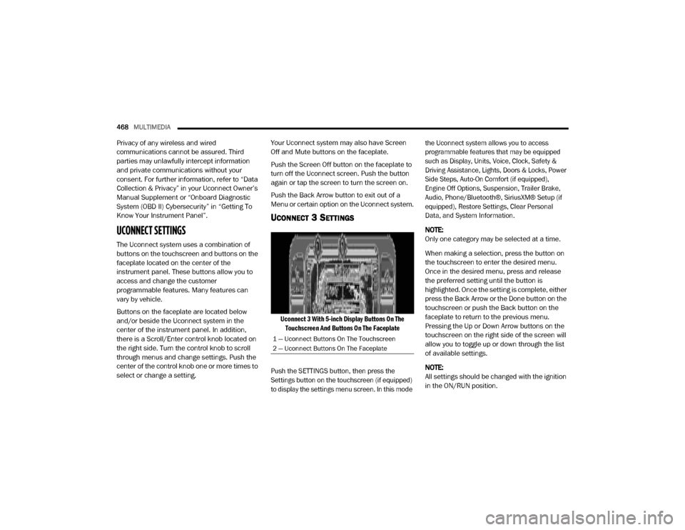
Uconnect 3 With 5-inch Display Buttons On The
Touchscreen And Buttons On The Faceplate
Push the SETTINGS button, then press the
Settings button on the touchscreen (if equipped)
to display the settings menu screen. In this mode the Uconnect system allows you to access
programmable features that may be equipped
such as Display, Units, Voice, Clock, Safety &
Driving Assistance, Lights, Doors & Locks, Power
Side Steps, Auto-On Comfort (if equipped),
Engine Off Options, Suspension, Trailer Brake,
Audio, Phone/Bluetooth®, SiriusXM® Setup (if
equipped), Restore Settings, Clear Personal
Data, and System Information.
NOTE:
Only one category may be selected at a time.
When making a selection, press the button on
the touchscreen to enter the desired menu.
Once in the desired menu, press and release
the preferred setting until the button is
highlighted. Once the setting is complete, either
press the Back Arrow or the Done button on the
touchscreen or push the Back button on the
faceplate to return to the previous menu.
Pressing the Up or Down Arrow buttons on the
touchscreen on the right side of the screen will
allow you to toggle up or down through the list
of available settings.
NOTE:
All settings should be changed with the ignition
in the ON/RUN position.
1 — Uconnect Buttons On The Touchscreen
2 — Uconnect Buttons On The Faceplate
20_DJD2_OM_EN_USC_t.book Page 468