clock Ram 3500 2020 Owner's Manual
[x] Cancel search | Manufacturer: RAM, Model Year: 2020, Model line: 3500, Model: Ram 3500 2020Pages: 568
Page 45 of 568
GETTING TO KNOW YOUR VEHICLE43
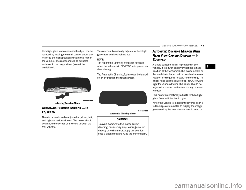
Headlight glare from vehicles behind you can be
reduced by moving the small control under the
mirror to the night position (toward the rear of
the vehicle). The mirror should be adjusted
while set in the day position (toward the
windshield).
Adjusting Rearview Mirror
AUTOMATIC DIMMING MIRROR — IF
E
QUIPPED
The mirror head can be adjusted up, down, left,
and right for various drivers. The mirror should
be adjusted to center on the view through the
rear window. This mirror automatically adjusts for headlight
glare from vehicles behind you.
NOTE:
The Automatic Dimming feature is disabled
when the vehicle is in REVERSE to improve rear
view viewing.
The Automatic Dimming feature can be turned
on or off through the touchscreen.
Automatic Dimming Mirror
AUTOMATIC DIMMING MIRROR WITH
R
EAR VIEW CAMERA DISPLAY — IF
E
QUIPPED
A single ball joint mirror is provided in the
vehicle. It is a twist on mirror that has a fixed
position at the windshield. The mirror installs on
the windshield button with a counterclockwise
rotation and requires no tools for mounting. The
mirror head can be adjusted up, down, left, and
right for various drivers. The mirror should be
adjusted to center on the view through the rear
window.
This mirror automatically adjusts for headlight
glare from vehicles behind you.
When the vehicle is placed into reverse gear, a
video display illuminates to display the image
generated by the rear view camera located on
CAUTION!
To avoid damage to the mirror during
cleaning, never spray any cleaning solution
directly onto the mirror. Apply the solution
onto a clean cloth and wipe the mirror clean.
2
20_DJD2_OM_EN_USC_t.book Page 43
Page 51 of 568
GETTING TO KNOW YOUR VEHICLE49
Rotate the headlight switch clockwise to the first
detent for parking light and instrument panel
light operation. Rotate the headlight switch to the
second detent for headlight, parking light, and
instrument panel light operation.
DAYTIME RUNNING LIGHTS (DRLS) — IF
E
QUIPPED
The headlights on your vehicle will illuminate
when the engine is started and the
transmission is in any gear except PARK. This
provides a constant "lights on" condition until
the ignition is placed in the OFF position. The
lights illuminate at less than half of normal
intensity. If the parking brake is applied, the
Daytime Running Lights (DRLs) will turn off.
Also, if a turn signal is activated, the DRL lamp
on the same side of the vehicle may turn off for
the duration of the turn signal activation. Once
the turn signal is no longer active, the DRL lamp
will illuminate.
NOTE:
If allowed by law in the country in which the
vehicle was purchased, the Daytime Running
Lights can be turned on and off using the Ucon -
nect system, refer to “Uconnect Settings” in
“Multimedia” for further information.
HIGH/LOW BEAM SWITCH
Push the multifunction lever toward the
instrument panel to switch the headlights to
high beam. Pulling the multifunction lever back
toward the steering wheel will turn the low
beams back on, or shut the high beams off.
AUTOMATIC HIGH BEAM HEADLAMP
C
ONTROL — IF EQUIPPED
The Automatic High Beam Headlamp Control
system provides increased forward lighting at
night by automating high beam control through
the use of a digital camera mounted on the inside
rearview mirror or forward facing camera. This
camera detects vehicle specific light and
automatically switches from high beams to low
beams until the approaching vehicle is out of view.
NOTE:
The Automatic High Beam Headlamp Control
can be turned on or off by selecting “ON”
under “Auto Dim High Beams” within your
Uconnect settings, as well as turning the
headlight switch to the AUTO position. Refer
to “Uconnect Settings” in “Multimedia” for
further information.
Broken, muddy, or obstructed headlights
and taillights of vehicles in the field of view
will cause headlights to remain on longer
(closer to the vehicle). Also, dirt, film, and
other obstructions on the windshield or
camera lens will cause the system to func -
tion improperly.
To opt out of the Advanced Auto High Beam
Sensitivity Control (default) and enter
Reduced High Beam Sensitivity Control (not
recommended), on vehicles equipped with
mirror controlled automatic high beams and
without the forward facing camera, toggle the
high beam lever six full on/off cycles within
10 seconds of placing the ignition in the ON
position. The system will return to the default
setting when the ignition is OFF.
If the windshield or Automatic High Beam
Headlamp Control mirror is replaced, the mirror
must be re-aimed to ensure proper
performance. See a local authorized dealer.
2
20_DJD2_OM_EN_USC_t.book Page 49
Page 52 of 568
50GETTING TO KNOW YOUR VEHICLE
To Activate
1. The Automatic High Beams are enabled
through the Uconnect system. Refer to
“Uconnect Settings” in “Multimedia” for
further information.
2. Turn the headlight switch to the AUTO headlight position.
3. Push the multifunction lever away from you (toward front of vehicle) to engage the high
beam mode.
NOTE:
The Automatic High Beams will not activate until
the vehicle is at or above 12 mph (20 km/h).
To Deactivate
1. Pull the multifunction lever toward you (or rearward in vehicle) to manually deactivate
the system (normal operation of low
beams).
2. Push back on the multifunction lever to reactivate the system.
The Automatic High Beams can also be
deactivated through the Uconnect system.
Refer to “Uconnect Settings” in “Multimedia”
for further information.
FLASH-TO-PASS
You can signal another vehicle with your
headlights by lightly pulling the multifunction
lever toward you. This will cause the high beam
headlights to turn on, and remain on, until the
lever is released.
AUTOMATIC HEADLIGHTS — IF EQUIPPED
This system automatically turns your headlights
on or off based on ambient light levels. To turn
the system on, turn the headlight switch to the
extreme clockwise position aligning the
indicator with the AUTO on the headlight switch.
When the system is on, the Headlight Time
Delay feature is also on. This means your
headlights will stay on for up to 90 seconds
after the ignition is placed in the OFF position.
To turn the Automatic System off, turn the
headlight switch counterclockwise to the O (off)
position.
NOTE:
The engine must be running before the head -
lights will come on in the Automatic mode.
DIRECTIONAL LED HEADLAMP SYSTEM
— I
F EQUIPPED
This is a system consisting of LED (low/high
beam) headlights that incorporate dynamic
cornering with 5-degree inboard/15-degree
outboard swivel. The headlights continuously
and automatically adapt to the driving
conditions around bends or when cornering
based on steering wheel angle.
The system directs the headlights to light up the
road in the best way, taking into account the
speed of the vehicle and the bend or corner
angle, as well as the speed of the vehicle while
the steering wheel is being turned.
The adaptive lights are automatically activated
when the vehicle is traveling above
approximately 5 mph (8 km/h).
This system can be turned on/off through the
Uconnect Settings under “Steering Directed
Lights”. Refer to Uconnect Settings in
“Multimedia” for further information.
20_DJD2_OM_EN_USC_t.book Page 50
Page 53 of 568
GETTING TO KNOW YOUR VEHICLE51
PARKING LIGHTS AND PANEL LIGHTS
To turn on the parking lights and instrument
panel lights, from the O (off) position, rotate the
headlight switch clockwise to the first detent. To
turn off the parking lights, rotate the headlight
switch back to the O (off) position.
HEADLIGHTS ON WITH WIPERS
(A
VAILABLE WITH AUTOMATIC
H
EADLIGHTS ONLY)
When this feature is active, the headlights will
turn on approximately 10 seconds after the
wipers are turned on if the headlight switch is
placed in the AUTO position. In addition, the
headlights will turn off when the wipers are
turned off, if they were turned on by this feature.
NOTE:
This feature can be programmed through the
Uconnect system. Refer to “Uconnect Settings”
in “Multimedia” for further information.
HEADLIGHT DELAY
To aid in your exit, your vehicle is equipped with
a headlight delay that will leave the headlights
on for up to 90 seconds. This delay is initiated
when the ignition is turned off while the headlight switch is on, and then the headlight
switch is cycled off. Headlight delay can be
canceled by either turning the headlight switch
on then off, or by placing the ignition in the ON/
RUN position.
NOTE:
This feature can be programmed through the
Uconnect system. Refer to “Uconnect Settings”
in “Multimedia” for further information.
LIGHTS-ON REMINDER
If the headlights, parking lights, or cargo lights
are left on after the ignition is placed in the OFF
position, a chime will sound and a message will
appear in the instrument cluster display when
the driver’s door is opened.
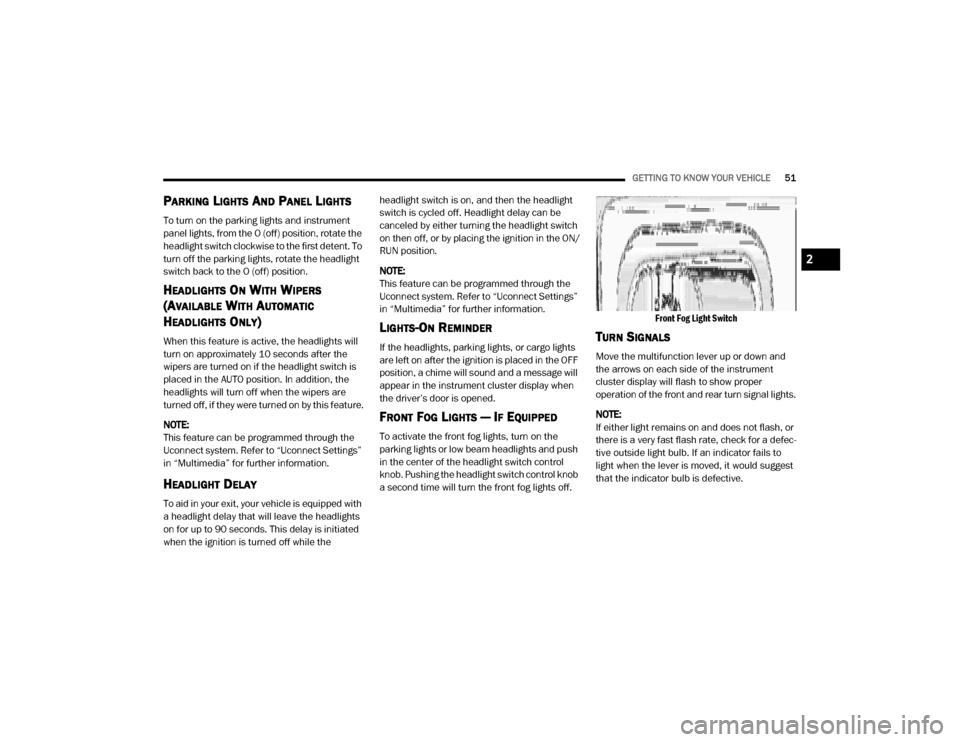
FRONT FOG LIGHTS — IF EQUIPPED
To activate the front fog lights, turn on the
parking lights or low beam headlights and push
in the center of the headlight switch control
knob. Pushing the headlight switch control knob
a second time will turn the front fog lights off.
Front Fog Light Switch
TURN SIGNALS
Move the multifunction lever up or down and
the arrows on each side of the instrument
cluster display will flash to show proper
operation of the front and rear turn signal lights.
NOTE:
If either light remains on and does not flash, or
there is a very fast flash rate, check for a defec
-
tive outside light bulb. If an indicator fails to
light when the lever is moved, it would suggest
that the indicator bulb is defective.
2
20_DJD2_OM_EN_USC_t.book Page 51
Page 60 of 568
58GETTING TO KNOW YOUR VEHICLE
Recirculation Button
Press and release this button on the touchscreen, or push the button on the faceplate, to change the system between
Recirculation mode and outside air mode. The Recirculation indicator and the A/C indicator illuminate when the
Recirculation button is pushed. Recirculation can be used when outside conditions, such as smoke, odors, dust, or
humidity are present. Recirculation can be used in all modes except for Defrost. Recirculation may be unavailable if
conditions exist that could create fogging on the inside of the windshield. The A/C can be deselected manually without
disturbing the mode control selection. Continuous use of the Recirculation mode may make the inside air stuffy and
window fogging may occur. Extended use of this mode is not recommended.
Temperature Control
Temperature Control regulates the temperature of the air forced through the Climate Control system. The temperature
increases as you turn the temperature control knob clockwise. The temperature decreases as you turn the temperature
control knob counterclockwise.
Blower Control
Blower Control regulates the amount of air forced through the Climate Control system. There are seven blower speeds
available. The blower speed increases as you turn the blower control knob clockwise from the lowest blower setting. The
blower speed decreases as you turn the blower control knob counterclockwise.
Icon Description
20_DJD2_OM_EN_USC_t.book Page 58
Page 67 of 568
GETTING TO KNOW YOUR VEHICLE65
Faceplate Blower Knob
Touchscreen Blower Buttons Blower Control
Blower Control regulates the amount of air forced through the climate system. There are seven blower speeds available.
The speeds can be selected using either the blower control knob on the faceplate or the buttons on the touchscreen.
Faceplate: The blower speed increases as you turn the blower control knob clockwise from the lowest blower setting. The
blower speed decreases as you turn the blower control knob counterclockwise.
Touchscreen:
Use the small blower icon to reduce the blower setting and the large blower icon to increase the blower
setting. Blower can also be selected by pressing the blower bar area between the icons.
NOTE:
On Uconnect 4C NAV With 12–inch display radios, pressing the blower control button below one turns the Climate Control
system OFF.
Faceplate Mode Button
Touchscreen Mode Buttons Mode Control
Mode Control regulates the airflow distribution. The airflow distribution outlets are: instrument panel outlets, floor outlets,
defrost outlets, and demist outlets.
Faceplate: Push the Mode Button to change the airflow distribution mode.
Touchscreen:
Press one of the “MODE” buttons to change the airflow distribution mode.
The Mode settings are as follows:
Icon Description
2
20_DJD2_OM_EN_USC_t.book Page 65
Page 95 of 568

GETTING TO KNOW YOUR VEHICLE93
(Continued)
To open a storage bin with the RamBox
unlocked, push and release the button located
on the lid. The RamBox lid will open upward to
allow hand access. Lift the lid to fully open.
NOTE:
RamBox will not open when the button is
pushed if the RamBox is locked.
RamBox Pushbutton And Lock
The interior of the RamBox will automatically
illuminate when the lid is opened. In addition to
the automatic illumination, there is a manual
on/off switch located at the rear of each storage
bin. Pushing the switch once will turn off the bin
lights, pushing the switch again will turn the
lights back on.
RamBox Light Switch
Cargo bins feature two removable drain plugs
(to allow water to drain from bins). To remove
plug, pull up on the edge. To install, push the
plug downward into drain hole.
NOTE:
Provisions are provided in the bins for cargo
dividers and shelf supports. These accessories
(in addition to other RamBox accessories) are
available from Mopar.Locking And Unlocking RamBox
Push and release the lock or unlock button on
the key fob to lock and unlock all doors, the
tailgate and the RamBox (if equipped). Refer to
“Keys” in this chapter for further details. The
RamBox storage bins can be locked using the
vehicle key. To lock and unlock the storage bin,
insert the key into the keyhole on the push
button and turn clockwise to lock or
counterclockwise to unlock. Always return the
key to the upright (vertical) position before
removing the key from the push button.
CAUTION!
Failure to follow the following items could
cause damage to the vehicle:
Assure that all cargo inside the storage bins
is properly secured.
Do not exceed cargo weight rating of 300 lbs
(136 kg) for 2500 and 3500 series vehicles
per bin.
CAUTION!
Leaving the lid open for extended periods of
time could cause the vehicle battery to
discharge. If the lid is required to stay open
for extended periods of time, it is
recommended that the bin lights be turned
off manually using the on/off switch.
CAUTION!
Ensure cargo bin lids are closed and
latched before moving or driving vehicle.
2
20_DJD2_OM_EN_USC_t.book Page 93
Page 98 of 568

96GETTING TO KNOW YOUR VEHICLE
To install the bed divider into a divider position,
perform the following:
1. Make sure the center handle is unlocked
using the vehicle key and rotate the center
handle vertically to release the divider side
gates.
2. With the side gates open, position the divider so the outboard ends align with the
intended slots in the sides of the bed.
Aligning Gate To Slots
3. Rotate the side gates closed so that the outboard ends are secured into the
intended slots of the bed.
4. Rotate the center handle horizontally to secure the side gates in the closed position.
Side Gates Closed
5. Lock the center handle to secure the panel into place.
BED RAIL TIE-DOWN SYSTEM — IF
E
QUIPPED
NOTE:
This feature is only available for vehicles
equipped with a RamBox.
There are two adjustable cleats on each side of
the bed that can be used to assist in securing
cargo.
Adjustable Cleats
Each cleat must be located and tightened down
in one of the detents, along either rail, in order
to keep cargo properly secure.
To move the cleat to any position on the rail,
turn the nut counterclockwise several turns.
Then pull out on the cleat and slide it to the
detent nearest the desired location. Make sure
the cleat is seated in the detent and tighten the
nut.
CAUTION!
The maximum load per cleat should not exceed
250 lbs (113 kg) and the angle of the load on
each cleat should not exceed 45 degrees
above horizontal, or damage to the cleat or
cleat rail may occur.
20_DJD2_OM_EN_USC_t.book Page 96
Page 243 of 568

STARTING AND OPERATING241
(Continued)
(Continued)
The following indicators should be used to
ensure that you have properly engaged the
transmission into the PARK position:
When shifting into PARK, pull the gear
selector toward you and move it all the way
counterclockwise until it stops.
Release the gear selector and make sure it is
fully seated in the PARK gate.
Look at the transmission gear position
display and verify that it indicates the PARK
position (P).
With brake pedal released, verify that the
gear selector will not move out of PARK.
REVERSE (R)
This range is for moving the vehicle backward.
Shift into REVERSE only after the vehicle has
come to a complete stop.
It is dangerous to shift out of PARK or
NEUTRAL if the engine speed is higher than
idle speed. If your foot is not firmly pressing
the brake pedal, the vehicle could accel -
erate quickly forward or in reverse. You
could lose control of the vehicle and hit
someone or something. Only shift into gear
when the engine is idling normally and your
foot is firmly pressing the brake pedal.
Unintended movement of a vehicle could
injure those in or near the vehicle. As with
all vehicles, you should never exit a vehicle
while the engine is running. Before exiting a
vehicle, always come to a complete stop,
then apply the parking brake, shift the
transmission into PARK, turn the engine off,
and remove the key fob. When the ignition
is in the LOCK/OFF (key removal) position
(or, with Keyless Enter-N-Go, when the igni -
tion is in the OFF mode), the transmission is
locked in PARK, securing the vehicle
against unwanted movement.
When leaving the vehicle, always make
sure the ignition is in the OFF mode,
remove the key fob from the vehicle, and
lock the vehicle.
WARNING! (Continued)
Never leave children alone in a vehicle, or
with access to an unlocked vehicle.
Allowing children to be in a vehicle unat -
tended is dangerous for a number of
reasons. A child or others could be seriously
or fatally injured. Children should be
warned not to touch the parking brake,
brake pedal or the transmission gear
selector.
Do not leave the key fob in or near the
vehicle (or in a location accessible to chil -
dren), and do not leave the ignition (in a
vehicle equipped with Keyless Enter-N-Go)
in the ACC or ON/RUN mode. A child could
operate power windows, other controls, or
move the vehicle.
CAUTION!
Before moving the transmission gear
selector out of PARK, you must turn the igni -
tion to the ON/RUN mode, and also press
the brake pedal. Otherwise, damage to the
gear selector could result.
WARNING! (Continued)
DO NOT race the engine when shifting from
PARK or NEUTRAL into another gear range,
as this can damage the drivetrain.
CAUTION! (Continued)
5
20_DJD2_OM_EN_USC_t.book Page 241
Page 321 of 568
STARTING AND OPERATING319
(Continued)
ENGINE RUNAWAY — DIESEL ENGINE
Diesel engine runaway is a rare condition
affecting diesel engines, where the engine
consumes its own lubrication oil and runs at
higher and higher RPM until it overspeeds to a
point where it destroys itself due to either
mechanical failure or engine seizure through
lack of lubrication.
REFUELING THE VEHICLE — GAS ENGINE
The fuel filler cap (gas cap) is located behind the
fuel filler door, on the left side of the vehicle.
Open the fuel door and remove the fuel filler cap
by turning it counter-clockwise.
Fuel Filler Cap
NOTE:
When removing the fuel filler cap, lay the cap
tether in the hook, located on the fuel filler door.
NOTE:
When the fuel nozzle “clicks” or shuts off, the
fuel tank is full.
WARNING!
In case of engine runaway due to flammable
fumes from fuel spills or turbocharger oil
leaks being sucked into the engine, do the
following to help avoid personal injury and/or
vehicle damage:
1. Turn the ignition switch to the OFF position.
2. Using a CO2 or dry chemical type fire
extinguisher, direct the spray from the fire
extinguisher into the grille on the driver side
so that the spray enters the engine air intake.
The inlet for the engine air intake is located
behind the drivers side headlamp and
receives air through the grille.
WARNING!
Never have any smoking materials lit in or
near the vehicle when the gas cap is
removed or the tank is being filled.
Never add fuel to the vehicle when the
engine is running.
A fire may result if gasoline is pumped into
a portable container that is inside of a
vehicle. You could be burned. Always place
gas containers on the ground while filling.
CAUTION!
Damage to the fuel system or emissions
control system could result from using an
improper fuel tank filler tube cap.
A poorly fitting fuel filler cap could let impu-
rities into the fuel system.
A poorly fitting fuel filler cap may cause the
“Malfunction Indicator Light (MIL)” to turn
on.
To avoid fuel spillage and overfilling, do not
“top off” the fuel tank after filling. When the
fuel nozzle “clicks” or shuts off, the fuel
tank is full.
WARNING! (Continued)
5
20_DJD2_OM_EN_USC_t.book Page 319