trailer Ram 3500 2020 Owner's Manual
[x] Cancel search | Manufacturer: RAM, Model Year: 2020, Model line: 3500, Model: Ram 3500 2020Pages: 568
Page 5 of 568

3
HEAD RESTRAINTS...............................................38 Front Head Restraints ................................. 39
Front Head Restraint Removal ................... 40
Rear Head Restraint Adjustment ................ 40
Rear Head Restraint Removal .................... 40
STEERING WHEEL.................................................41
Tilt Steering Column ................................... 41
Heated Steering Wheel — If Equipped ....... 41
DRIVER ADJUSTABLE PEDALS —
IF EQUIPPED .........................................................42
MIRRORS ..............................................................42
Inside Day/Night Mirror — If Equipped ...... 42
Automatic Dimming Mirror — If Equipped ... 43
Automatic Dimming Mirror With Rear
View Camera Display — If Equipped .......... 43 Outside Mirrors ........................................... 44
Driver's Outside Automatic Dimming
Mirror — If Equipped .................................... 44 Power Mirrors — If Equipped ...................... 44
Power Convex Mirror Switch — If Equipped .. 45
Trailer Towing Mirrors — If Equipped ......... 46
Heated Mirrors — If Equipped .................... 46
Tilt Side Mirrors In Reverse — If Equipped ... 46
Power Folding Outside Mirrors For
Standard And Trailer Tow — If Equipped .... 46 Illuminated Vanity Mirror — If Equipped ..... 48 EXTERIOR LIGHTS ............................................... 48
Multifunction Lever...................................... 48
Headlight Switch .......................................... 48
Daytime Running Lights (DRLs) —
If Equipped ................................................... 49 High/Low Beam Switch ............................... 49
Automatic High Beam Headlamp
Control — If Equipped .................................. 49 Flash-To-Pass ............................................... 50
Automatic Headlights — If Equipped .......... 50
Directional LED Headlamp System —
If Equipped ................................................... 50 Parking Lights And Panel Lights ................. 51
Headlights On With Wipers (Available
With Automatic Headlights Only) ................ 51 Headlight Delay............................................ 51
Lights-On Reminder ..................................... 51
Front Fog Lights — If Equipped .................. 51
Turn Signals ................................................. 51
Lane Change Assist — If Equipped ............. 52
Cargo Lights/Trailer Spotter Lights
With Bed Lights — If Equipped .................... 52 Battery Saver ............................................... 53 INTERIOR LIGHTS ................................................53
Courtesy Lights ............................................ 53
Illuminated Entry ........................................ 54
WINDSHIELD WIPERS AND WASHERS .............55
Windshield Wipers ...................................... 55
Rain Sensing Wipers — If Equipped ........... 56
CLIMATE CONTROLS ...........................................57
Manual Climate Control Overview .............. 57
Automatic Climate Control Overview .......... 61
Climate Control Functions........................... 67
Automatic Temperature Control (ATC) ...... 67
Operating Tips ............................................. 68
WINDOWS ............................................................70
Power Windows .......................................... 70
Wind Buffeting ............................................ 71
POWER SUNROOF — IF EQUIPPED ....................72
Single Pane Power Sunroof — If Equipped ... 72
HOOD......................................................................74
To Open The Hood ...................................... 74
To Close The Hood....................................... 74
TAILGATE ...............................................................74
Opening ........................................................ 74
Closing.......................................................... 75
Bed Step — If Equipped ............................... 75
20_DJD2_OM_EN_USC_t.book Page 3
Page 9 of 568
7
PARKSENSE REAR PARK ASSIST —
IF EQUIPPED ...................................................... 296 ParkSense Sensors ...................................296
ParkSense Warning Display ......................296
ParkSense Display ..................................... 297Enabling And Disabling ParkSense ..........299
Service The ParkSense Rear Park
Assist System .............................................299 Cleaning The ParkSense System ..............299
ParkSense System Usage Precautions ....299
PARKSENSE FRONT AND REAR
PARK ASSIST ..................................................... 301
ParkSense Sensors ...................................301
ParkSense Warning Display ......................301
ParkSense Display ..................................... 301Enabling And Disabling Front And/Or
Rear ParkSense .........................................304 Service The ParkSense Front/Rear
Park Assist System ....................................305 Cleaning The ParkSense System ..............305
ParkSense System Usage Precautions ....305
LANESENSE — IF EQUIPPED ........................... 306
LaneSense Operation ................................306Turning LaneSense On Or Off ...................307LaneSense Warning Message ..................307
Changing LaneSense Status .....................309 PARKVIEW REAR BACK UP CAMERA..............309
AUX Camera — If Equipped ...................... 311
SURROUND VIEW CAMERA SYSTEM —
IF EQUIPPED ....................................................... 312
AUX Camera — If Equipped ...................... 318
ENGINE RUNAWAY — DIESEL ENGINE ............ 319
REFUELING THE VEHICLE — GAS ENGINE ...... 319
Loose Fuel Filler Cap Message ................ 320
REFUELING THE VEHICLE — DIESEL ENGINE ... 320
Diesel Exhaust Fluid .................................. 321
VEHICLE LOADING ............................................324
Gross Vehicle Weight Rating (GVWR) ...... 324
Payload ....................................................... 324Gross Axle Weight Rating (GAWR) ............ 324
Tire Size ...................................................... 324
Rim Size ..................................................... 324
Inflation Pressure ...................................... 324
Curb Weight................................................ 324
Loading ....................................................... 324
TRAILER TOWING ............................................... 325
Common Towing Definitions ..................... 325Trailer Hitch Type and Maximum
Trailer Weight ............................................. 329 Trailer Towing Weights (Maximum Trailer
Weight Ratings) ......................................... 330 Trailer And Tongue Weight ........................ 330
Towing Requirements ............................... 330Towing Tips ................................................ 335 SNOWPLOW ...................................................... 336
Before Plowing ........................................... 337
Snowplow Prep Package Model
Availability .................................................. 337 Over The Road Operation With
Snowplow Attached ................................... 338 Operating Tips............................................ 338General Maintenance................................ 338
RECREATIONAL TOWING (BEHIND
MOTORHOME, ETC.) ......................................... 339
Towing This Vehicle Behind Another
Vehicle ........................................................ 339 Recreational Towing — Two-Wheel Drive
Models........................................................ 339 Recreational Towing — Four-Wheel Drive
Models........................................................ 340
DRIVING TIPS ..................................................... 343
Driving On Slippery Surfaces ................... 343
Driving Through Water ............................. 343
Off-Road Driving Tips ................................. 344
IN CASE OF EMERGENCY
HAZARD WARNING FLASHERS ...................... 346
ASSIST AND SOS SYSTEM — IF EQUIPPED .... 346General Information .................................. 350
20_DJD2_OM_EN_USC_t.book Page 7
Page 47 of 568
GETTING TO KNOW YOUR VEHICLE45
The power mirror controls consist of mirror
select buttons and a four-way mirror control
switch.
To adjust a mirror, push either the L (left) or R
(right) button to select the mirror that you want
to adjust.
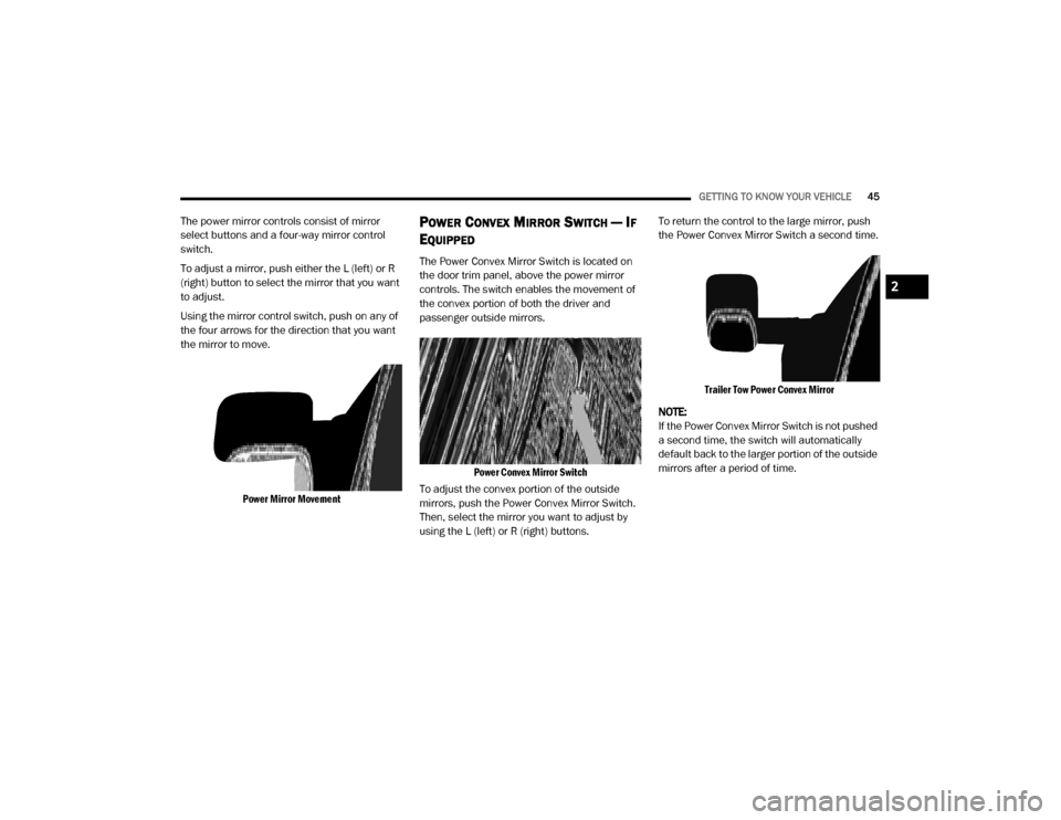
Using the mirror control switch, push on any of
the four arrows for the direction that you want
the mirror to move.
Power Mirror Movement
POWER CONVEX MIRROR SWITCH — IF
E
QUIPPED
The Power Convex Mirror Switch is located on
the door trim panel, above the power mirror
controls. The switch enables the movement of
the convex portion of both the driver and
passenger outside mirrors.
Power Convex Mirror Switch
To adjust the convex portion of the outside
mirrors, push the Power Convex Mirror Switch.
Then, select the mirror you want to adjust by
using the L (left) or R (right) buttons. To return the control to the large mirror, push
the Power Convex Mirror Switch a second time.
Trailer Tow Power Convex Mirror
NOTE:
If the Power Convex Mirror Switch is not pushed
a second time, the switch will automatically
default back to the larger portion of the outside
mirrors after a period of time.
2
20_DJD2_OM_EN_USC_t.book Page 45
Page 48 of 568

46GETTING TO KNOW YOUR VEHICLE
TRAILER TOWING MIRRORS — IF
E
QUIPPED
These mirrors are designed with an adjustable
mirror head to provide a greater vision range
when towing extra-wide loads. To change
position inboard or outboard, the mirror head
should be rotated (flipped in or out).
Trailer Towing Position
NOTE:
Fold the trailer towing mirrors rearward prior to
entering an automated car wash.
A small blindspot mirror is located next to main
mirror and can be adjusted separately.
Blindspot Mirror
HEATED MIRRORS — IF EQUIPPED
These mirrors are heated to melt frost
or ice. This feature will be activated
whenever you turn on the rear window
defroster (if equipped).
Refer to “Climate Controls” in this chapter for
further information.
TILT SIDE MIRRORS IN REVERSE — IF
E
QUIPPED
Tilt Side Mirrors In Reverse provides automatic
outside mirror positioning which will aid the
driver’s view of the ground rearward of the front
doors. The outside mirrors will move slightly
downward from the present position when the
vehicle is shifted into REVERSE. The outside mirrors will then return to the original position
when the vehicle is shifted out of the REVERSE
position. Each stored memory setting will have
an associated Tilt Side Mirrors In Reverse
position.
NOTE:
The Tilt Side Mirrors In Reverse feature is not
turned on when delivered from the factory.
This feature can be programmed through the
Uconnect system. Refer to “Uconnect Settings”
in “Multimedia” for further information.
POWER FOLDING OUTSIDE MIRRORS
F
OR STANDARD AND TRAILER TOW — IF
E
QUIPPED
If equipped with power folding mirrors, they can
be electrically folded rearward and unfolded
into the drive position.
The switch for the power folding mirrors is
located between the power mirror switches L
(left) and R (right). Push the switch once and the
mirrors will fold in, push the switch a second
time and the mirrors will return to the normal
driving position.
20_DJD2_OM_EN_USC_t.book Page 46
Page 50 of 568

48GETTING TO KNOW YOUR VEHICLE
ILLUMINATED VANITY MIRROR — IF
E
QUIPPED
Illuminated vanity mirrors are located on each
sun visor. To use the mirror, rotate the sun visor
down and swing the mirror cover upward. The
lights will turn on automatically. Closing the
mirror cover turns off the light.
Lift Cover For Illuminated Mirror
“Slide-On-Rod” Features Of Sun Visor — If
Equipped
The sun visor “Slide-On-Rod” feature allows for
additional flexibility in positioning the visor to
block out the sun.
To use the “Slide-On-Rod” feature, rotate the
sun visor downward and unclip it. Pull the sun
visor along the “Slide-On-Rod” until the sun
visor is in the desired position.
“Slide-On-Rod” Extender
EXTERIOR LIGHTS
MULTIFUNCTION LEVER
The multifunction lever is located on the left
side of the steering column.
Multifunction Lever
HEADLIGHT SWITCH
The headlight switch is located on the left side
of the instrument panel. This switch controls the
operation of the headlights, parking lights,
automatic headlights (if equipped), instrument
panel light dimming, cargo light/trailer spotter
lights (if equipped), and fog lights (if equipped).
Headlight Switch
1 — Rotate Headlight Control
2 — Ambient Light Dimmer Control
3 — Instrument Panel Light Dimmer Control
4 — Push Cargo Light Control
5 — Push Front Fog Light Control
20_DJD2_OM_EN_USC_t.book Page 48
Page 54 of 568
52GETTING TO KNOW YOUR VEHICLE
LANE CHANGE ASSIST — IF EQUIPPED
Tap the multifunction lever up or down once,
without moving beyond the detent, and the turn
signal (right or left) will flash three times then
automatically turn off.
CARGO LIGHTS/TRAILER SPOTTER
L
IGHTS WITH BED LIGHTS — IF
E
QUIPPED
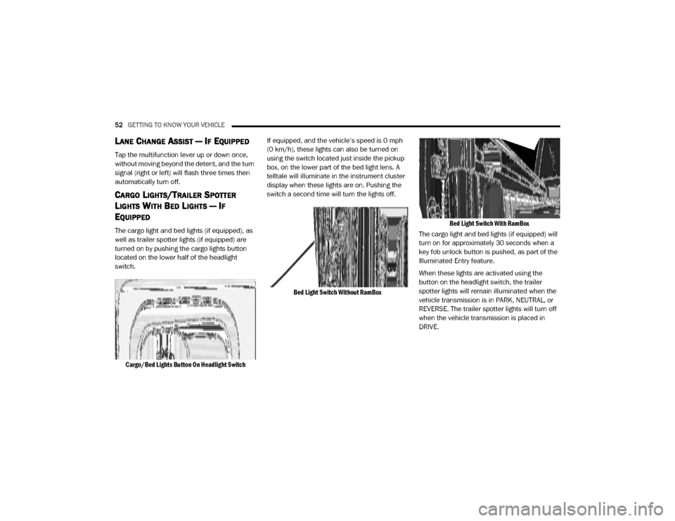
The cargo light and bed lights (if equipped), as
well as trailer spotter lights (if equipped) are
turned on by pushing the cargo lights button
located on the lower half of the headlight
switch.
Cargo/Bed Lights Button On Headlight Switch
If equipped, and the vehicle’s speed is 0 mph
(0 km/h), these lights can also be turned on
using the switch located just inside the pickup
box, on the lower part of the bed light lens. A
telltale will illuminate in the instrument cluster
display when these lights are on. Pushing the
switch a second time will turn the lights off.
Bed Light Switch Without RamBox Bed Light Switch With RamBox
The cargo light and bed lights (if equipped) will
turn on for approximately 30 seconds when a
key fob unlock button is pushed, as part of the
Illuminated Entry feature.
When these lights are activated using the
button on the headlight switch, the trailer
spotter lights will remain illuminated when the
vehicle transmission is in PARK, NEUTRAL, or
REVERSE. The trailer spotter lights will turn off
when the vehicle transmission is placed in
DRIVE.
20_DJD2_OM_EN_USC_t.book Page 52
Page 93 of 568

GETTING TO KNOW YOUR VEHICLE91
There are stampings in the sheet metal on the
inner side bulkheads of the box in front of and
behind both wheel housings. Place wooden
boards across the box from side to side to
create separate load compartments in the
pickup box.
There are four tie-down cleats bolted to the
lower sides of the pickup box that can sustain
loads up to 1000 lbs (450 kg) total.
CARGO CAMERA — IF EQUIPPED
Your vehicle may be equipped with the Cargo
Camera that allows you to see an image of the
inside of the pickup box. The image will be
displayed in the Uconnect screen.
The Cargo Camera is located in the bottom
center area of the Center High-Mounted
Stoplamp (CHMSL).
A touchscreen button to indicate the current
active camera image being displayed is made
available whenever the Cargo Camera image is
displayed.
A touchscreen button to switch the display to
rear view camera image is made available
whenever the Cargo Camera image is displayed. A touchscreen button "X" to disable display of
the camera image is made available when the
vehicle is not in REVERSE gear.
A display timer is initiated when the Cargo
Camera image is displayed. The image will
continue to be displayed until the display timer
exceeds 10 seconds and the vehicle speed is
above 8 mph (13 km/h) or the touchscreen
button "X" to disable display of the Cargo
Camera image is pressed.
Cargo Camera With Dynamic Centerline
(Available With Surround View Camera Only) — If
Equipped
The Dynamic Centerline feature provides an
overlay on the Cargo Camera display screen
that aligns to the center of the pickup box to aid
in hooking up a fifth wheel camper or
gooseneck trailer. The centerline auto aligns to
the center of the pickup box, and can also be
manually adjusted. The centerline will adjust in
response to steering angle inputs, and will not
obstruct the gooseneck receiver or an
approaching trailer gooseneck in the camera
feed.
Activation
The Dynamic Centerline feature can be
activated through the Uconnect settings by
pressing the Cargo Camera soft button,
followed by the “Adjust Centerline” soft button
on the touchscreen.
If the Dynamic Centerline feature is turned on,
the overlay will display anytime the Cargo
Camera image is displayed.
Adjusting Centerline
Follow the steps below to manually adjust the
centerline:
1. Press the “Adjust Centerline” soft button
located in the bottom right corner of the
Cargo Camera display.
2. Use the arrows on the bottom left corner of the Cargo Camera display to adjust the
centerline horizontally or vertically.
3. Once the desired position is achieved, press the “Accept” button to set the centerline to
the newly specified position.
2
20_DJD2_OM_EN_USC_t.book Page 91
Page 109 of 568
GETTING TO KNOW YOUR INSTRUMENT PANEL107
3. Instrument Cluster Display
When the appropriate conditions exist,
this display shows the instrument cluster
display messages. Refer to “Instrument
Cluster Display” in “Getting To Know Your
Instrument Panel” for further informa-
tion.
4. Oil Pressure Gauge
The pointer should always indicate the oil
pressure when the engine is running. A
continuous high or low reading under
normal driving conditions may indicate a
lubrication system malfunction. Imme -
diate service should be obtained from an
authorized dealer.
5. Speedometer
Indicates vehicle speed.
6. Fuel Gauge
The pointer shows the level of fuel in the
fuel tank when the ignition is in the ON/
RUN position.
The fuel pump symbol points
to the side of the vehicle where
the fuel door is located.
Refer to “Refueling The Vehicle — Gas
Engine” in “Starting And Operating” for
further information.
7. Temperature Gauge
The gauge pointer shows engine coolant
temperature. The pointer positioned
within the normal range indicates that
the engine cooling system is operating
satisfactorily.
The gauge pointer will likely indicate a
higher temperature when driving in hot
weather, up mountain grades, or when
towing a trailer. It should not be allowed
to exceed the upper limits of the normal
operating range.
WARNING!
A hot engine cooling system is dangerous.
You or others could be badly burned by steam
or boiling coolant. You may want to call an
authorized dealer for service if your vehicle
overheats. If you decide to look under the
hood yourself, refer to the warnings under
“Cooling System Pressure Cap” in see
“Servicing And Maintenance” for further
information.
CAUTION!
Driving with a hot engine cooling system
could damage your vehicle. If the
temperature gauge reads “H,” pull over and
stop the vehicle. Idle the vehicle with the air
conditioner turned off until the pointer drops
back into the normal range. If the pointer
remains on the “H,” turn the engine off
immediately and call an authorized dealer for
service.
3
20_DJD2_OM_EN_USC_t.book Page 107
Page 111 of 568
GETTING TO KNOW YOUR INSTRUMENT PANEL109
The fuel pump symbol points
to the side of the vehicle where
the fuel door is located.
Refer to “Refueling The Vehicle — Gas
Engine” in “Starting And Operating” for
further information.
5. Temperature Gauge
The gauge pointer shows engine coolant
temperature. The pointer positioned
within the normal range indicates that
the engine cooling system is operating
satisfactorily.
The gauge pointer will likely indicate a
higher temperature when driving in hot
weather, up mountain grades, or when
towing a trailer. It should not be allowed
to exceed the upper limits of the normal
operating range.
WARNING!
A hot engine cooling system is dangerous.
You or others could be badly burned by steam
or boiling coolant. You may want to call an
authorized dealer for service if your vehicle
overheats. If you decide to look under the
hood yourself, refer to the warnings under
“Cooling System Pressure Cap” in see
“Servicing And Maintenance” for further
information.
CAUTION!
Driving with a hot engine cooling system
could damage your vehicle. If the
temperature gauge reads “H,” pull over and
stop the vehicle. Idle the vehicle with the air
conditioner turned off until the pointer drops
back into the normal range. If the pointer
remains on the “H,” turn the engine off
immediately and call an authorized dealer for
service.
3
20_DJD2_OM_EN_USC_t.book Page 109
Page 116 of 568

114GETTING TO KNOW YOUR INSTRUMENT PANEL
INSTRUMENT CLUSTER DISPLAY
C
ONTROLS
The instrument cluster display features a driver
interactive display that is located in the
instrument cluster.
Base Instrument Cluster Display Premium Instrument Cluster Display
The instrument cluster display menu items may
consist of the following:
Speedometer
Vehicle Info
Driver Assist — If Equipped
Fuel Economy
Trip Info
Trailer Tow — If Equipped
Audio
Messages
Screen Set Up
Commercial Settings — If Equipped
The system allows the driver to select
information by pushing the following instrument
cluster display control buttons located on the
left side of the steering wheel:
Instrument Cluster Display Control Buttons
1 – Instrument Cluster Display Controls
2 – Instrument Cluster Display Screen
1 – Instrument Cluster Display Controls
2 – Instrument Cluster Display Screen
20_DJD2_OM_EN_USC_t.book Page 114